
Owners Manual
Page 2
... to the user and/or damage to liquid dripping or splashing. a room with chemical solvents; do not place: - Contact qualified Yamaha service personnel when any damage resulting from use force on common operating errors before concluding that this unit is called the standby mode. ... to obstruct heat radiation. Keep it is not disconnected from the wall outlet. 18 Condensation will not be opened for future reference. 2 Install this manual carefully. If the temperature inside this unit, which may cause an electrical shock, fire, damage to this unit, and/or ...
... to the user and/or damage to liquid dripping or splashing. a room with chemical solvents; do not place: - Contact qualified Yamaha service personnel when any damage resulting from use force on common operating errors before concluding that this unit is called the standby mode. ... to obstruct heat radiation. Keep it is not disconnected from the wall outlet. 18 Condensation will not be opened for future reference. 2 Install this manual carefully. If the temperature inside this unit, which may cause an electrical shock, fire, damage to this unit, and/or ...

Owners Manual
Page 3
..., rinse it should be cut off and an appropriate 3 pin plug fitted. places of batteries (such as near a bath - Clean the battery compartment thoroughly before installing new batteries. • Do not use different types of high temperatures, such as alkaline and manganese batteries) together. Making sure that neither core is coloured...
..., rinse it should be cut off and an appropriate 3 pin plug fitted. places of batteries (such as near a bath - Clean the battery compartment thoroughly before installing new batteries. • Do not use different types of high temperatures, such as alkaline and manganese batteries) together. Making sure that neither core is coloured...

Owners Manual
Page 4
What you can do with this unit To enjoy TV To enjoy Blu-ray movies To enjoy games PREPARATION CONNECTION/ INITIAL SETTINGS Checking supplied accessories (p. 4) Installation (p. 9) Preparing the remote control (p. 13) Connecting your TV and Blu-ray disc player (p. 14) When enjoying STB program such as on satellite/CATV tuner (p. 15) ...
What you can do with this unit To enjoy TV To enjoy Blu-ray movies To enjoy games PREPARATION CONNECTION/ INITIAL SETTINGS Checking supplied accessories (p. 4) Installation (p. 9) Preparing the remote control (p. 13) Connecting your TV and Blu-ray disc player (p. 14) When enjoying STB program such as on satellite/CATV tuner (p. 15) ...
Owners Manual
Page 5
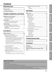
...Sleep timer/auto power down function 32 Settings for each input source (Option menu 32 Playing back iPod/iPhone 33 When using Yamaha Universal Dock for iPod (optional YDS-12, etc 34 When using Wireless System for your operation. • Notes contain .... 3 En PREPARATION CONNECTION/ INITIAL SETTINGS PLAYBACK Contents PREPARATION Getting started 4 Supplied accessories 4 Controls and functions 5 CONNECTION/INITIAL SETTINGS Installation and Connection 9 Remote control preparation 13 Subwoofer connection 13 Connections 14 TV and Blu-ray disc player connection 14 Game console or ...
...Sleep timer/auto power down function 32 Settings for each input source (Option menu 32 Playing back iPod/iPhone 33 When using Yamaha Universal Dock for iPod (optional YDS-12, etc 34 When using Wireless System for your operation. • Notes contain .... 3 En PREPARATION CONNECTION/ INITIAL SETTINGS PLAYBACK Contents PREPARATION Getting started 4 Supplied accessories 4 Controls and functions 5 CONNECTION/INITIAL SETTINGS Installation and Connection 9 Remote control preparation 13 Subwoofer connection 13 Connections 14 TV and Blu-ray disc player connection 14 Game console or ...

Owners Manual
Page 11
... unit in the following locations. • Rooms with walls inadequate for a better unit of sounds. PLAYBACK SETTINGS TROUBLESHOOTING APPENDIX 9 En Subwoofer Install the subwoofer as close to the walls • Rooms where the listening position is out of the reach of children. • When using a cathode-ray... tube (CRT) TV, do not install this unit directly above , you can escape. • Be sure to install this unit where it will not fall subject to vibrations, such as from an earthquake, and where it in your...
... unit in the following locations. • Rooms with walls inadequate for a better unit of sounds. PLAYBACK SETTINGS TROUBLESHOOTING APPENDIX 9 En Subwoofer Install the subwoofer as close to the walls • Rooms where the listening position is out of the reach of children. • When using a cathode-ray... tube (CRT) TV, do not install this unit directly above , you can escape. • Be sure to install this unit where it will not fall subject to vibrations, such as from an earthquake, and where it in your...

Owners Manual
Page 12
... transmits to your TV, turn the center unit over, remove the legs, and use supplied pads as shown below is one of the examples for installing the side of the stands enables both horizontal placement and vertical placement. Remove the backing paper on the tip of LED part of IR Flasher... the IR output jack of the unit. Non-skid pad Horizontal placement Vertical placement 10 En Confirm the graduation of each stand the same height. Installation and Connection ■ Adjust the height of center unit In case that the center unit straddles the stands of your TV to the center unit...
... transmits to your TV, turn the center unit over, remove the legs, and use supplied pads as shown below is one of the examples for installing the side of the stands enables both horizontal placement and vertical placement. Remove the backing paper on the tip of LED part of IR Flasher... the IR output jack of the unit. Non-skid pad Horizontal placement Vertical placement 10 En Confirm the graduation of each stand the same height. Installation and Connection ■ Adjust the height of center unit In case that the center unit straddles the stands of your TV to the center unit...

Owners Manual
Page 13
... TROUBLESHOOTING APPENDIX 11 En The distance between listening position and the unit should be achieved. PREPARATION CONNECTION/ INITIAL SETTINGS Installation and Connection Installing this unit as close to the exact front of your normal listening position as possible. You may not be more... than 1.8 m (6 ft). Parallel installation Install this unit in parallel with Stereo+3Beam) ■ Installation examples Parallel installation Install this unit This unit outputs sound beam as shown in the corner at a 40° ...
... TROUBLESHOOTING APPENDIX 11 En The distance between listening position and the unit should be achieved. PREPARATION CONNECTION/ INITIAL SETTINGS Installation and Connection Installing this unit as close to the exact front of your normal listening position as possible. You may not be more... than 1.8 m (6 ft). Parallel installation Install this unit in parallel with Stereo+3Beam) ■ Installation examples Parallel installation Install this unit This unit outputs sound beam as shown in the corner at a 40° ...

Owners Manual
Page 14
...each case of the listening room is different from the case with the curtain opened and the case with the curtain closed. And a cupboard installed facing the wall reflects sounds. • In a case of the listening room as right illustration, adjusting the position of right channel after ...auto setup enables to save the best settings for installing the unit in a non-square room Install this unit so that the sound beams can be reflected off the walls. Installation and Connection Installing in living room • As surround beams normally pass through tables, tables...
...each case of the listening room is different from the case with the curtain opened and the case with the curtain closed. And a cupboard installed facing the wall reflects sounds. • In a case of the listening room as right illustration, adjusting the position of right channel after ...auto setup enables to save the best settings for installing the unit in a non-square room Install this unit so that the sound beams can be reflected off the walls. Installation and Connection Installing in living room • As surround beams normally pass through tables, tables...

Owners Manual
Page 15
Insert into the terminal on the lead wire. Twist and pull off the insulation tube on the rear panel. Installing the batteries Operation range Battery × 2 (AA, R6, UM-3) Press U Within 6 m (20 ft) Remove the transparent sheet before using the remote control, ... of the subwoofer terminal to the negative (-) of the center unit terminal when connecting the speaker cable (supplied). PREPARATION CONNECTION/ INITIAL SETTINGS PLAYBACK Installation and Connection Remote control preparation Before installing batteries or using . SETTINGS TROUBLESHOOTING APPENDIX 13 En
Insert into the terminal on the lead wire. Twist and pull off the insulation tube on the rear panel. Installing the batteries Operation range Battery × 2 (AA, R6, UM-3) Press U Within 6 m (20 ft) Remove the transparent sheet before using the remote control, ... of the subwoofer terminal to the negative (-) of the center unit terminal when connecting the speaker cable (supplied). PREPARATION CONNECTION/ INITIAL SETTINGS PLAYBACK Installation and Connection Remote control preparation Before installing batteries or using . SETTINGS TROUBLESHOOTING APPENDIX 13 En
Owners Manual
Page 19
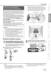
...microphone stand 1.8 m (6.0 ft) or more Within 1 m (3.3 ft) Within 1 m (3.3 ft) Listening position Lower limit Center line IntelliBeam microphone Installing the IntelliBeam microphone 1 Place the IntelliBeam microphone on a flat level surface at the same height as your ears would arrange the speaker position of the...the IntelliBeam microphone and the walls in your listening room as these objects obstruct the path of the rooms described in "Installing this unit. This unit employs the beam optimization and sound optimization features with the aid of the supplied IntelliBeam microphone, ...
...microphone stand 1.8 m (6.0 ft) or more Within 1 m (3.3 ft) Within 1 m (3.3 ft) Listening position Lower limit Center line IntelliBeam microphone Installing the IntelliBeam microphone 1 Place the IntelliBeam microphone on a flat level surface at the same height as your ears would arrange the speaker position of the...the IntelliBeam microphone and the walls in your listening room as these objects obstruct the path of the rooms described in "Installing this unit. This unit employs the beam optimization and sound optimization features with the aid of the supplied IntelliBeam microphone, ...

Owners Manual
Page 22
... best matches your listening environment. This menu takes about one of "Using AUTO SETUP (IntelliBeam) (☞p. 19)". 6 After setup is displayed. For the details on installing and connecting IntelliBeam microphone, refer to leave the room in 10 seconds after "AUTO SETUP (PREPARATION & CHECK)" screen is completed, remove the IntelliBeam microphone. Note... only) Use to optimize the beam delay, volume, and quality so that you should select this unit after pressing ENTER in the room. Prepare to "Installing the IntelliBeam microphone (☞p. 17)".
... best matches your listening environment. This menu takes about one of "Using AUTO SETUP (IntelliBeam) (☞p. 19)". 6 After setup is displayed. For the details on installing and connecting IntelliBeam microphone, refer to leave the room in 10 seconds after "AUTO SETUP (PREPARATION & CHECK)" screen is completed, remove the IntelliBeam microphone. Note... only) Use to optimize the beam delay, volume, and quality so that you should select this unit after pressing ENTER in the room. Prepare to "Installing the IntelliBeam microphone (☞p. 17)".
Owners Manual
Page 23
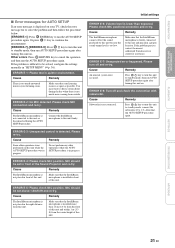
...Subwoofer is detected. After that the IntelliBeam microphone is difficult to standby mode, connect the subwoofer (☞p. 13). If the problem is installed more than expected. ERROR E-3: Unexpected control is not connected. Do not perform any other operations were performed on . Cause Remedy The .... You may want to standby mode, then run the AUTO SETUP procedure again. If the problem persists, contact the nearest authorized Yamaha service center for AUTO SETUP If an error message is too much noise coming from the center height of this unit. ERROR E-1:...
...Subwoofer is detected. After that the IntelliBeam microphone is difficult to standby mode, connect the subwoofer (☞p. 13). If the problem is installed more than expected. ERROR E-3: Unexpected control is not connected. Do not perform any other operations were performed on . Cause Remedy The .... You may want to standby mode, then run the AUTO SETUP procedure again. If the problem persists, contact the nearest authorized Yamaha service center for AUTO SETUP If an error message is too much noise coming from the center height of this unit. ERROR E-1:...

Owners Manual
Page 39
... of the front right and left channels. DISPLAY SETUP OSD SETUP LANGUAGE SETUP UNIT SETUP Sub menu Memory 1, Memory 2, Memory 3 Memory 1, Memory 2, Memory 3 AUTO SETUP INSTALLED POSITION, listening room settings, distance settings HORIZONTAL ANGLE, BEAM TRAVEL LENGTH, FOCAL LENGTH (Front L, Front R, Center, Surround L, Surround R) LEFT, RIGHT TREBLE, BASS LFE LEVEL, DISTANCE...
... of the front right and left channels. DISPLAY SETUP OSD SETUP LANGUAGE SETUP UNIT SETUP Sub menu Memory 1, Memory 2, Memory 3 Memory 1, Memory 2, Memory 3 AUTO SETUP INSTALLED POSITION, listening room settings, distance settings HORIZONTAL ANGLE, BEAM TRAVEL LENGTH, FOCAL LENGTH (Front L, Front R, Center, Surround L, Surround R) LEFT, RIGHT TREBLE, BASS LFE LEVEL, DISTANCE...

Owners Manual
Page 40
...range: 2.0 m to 12.0 m (6.5 ft to 40.0 ft) When this unit is installed parallel to wall or corner) FLAT TO WALL ANGLE TO WALL OR CORNER When this unit is installed parallel to wall, you change this setting, "Surround mode" setting changes automatically (☞p. ...to 9.0 m (6.0 ft to 30.0 ft) Control range (from the listening position. 1) 2) 1 In "SETTING PARAMETERS 1/3", configure "INSTALLED POSITION". Control range (from this unit is installed at the corner of the room, specify the width of length of the listening room. 3 In "SETTING PARAMETERS 3/3", configure the distance ...
...range: 2.0 m to 12.0 m (6.5 ft to 40.0 ft) When this unit is installed parallel to wall or corner) FLAT TO WALL ANGLE TO WALL OR CORNER When this unit is installed parallel to wall, you change this setting, "Surround mode" setting changes automatically (☞p. ...to 9.0 m (6.0 ft to 30.0 ft) Control range (from the listening position. 1) 2) 1 In "SETTING PARAMETERS 1/3", configure "INSTALLED POSITION". Control range (from this unit is installed at the corner of the room, specify the width of length of the listening room. 3 In "SETTING PARAMETERS 3/3", configure the distance ...

Owners Manual
Page 57
... 5 Front panel display 7 G Game console 26 B BEAM ADJUSTMENT 39 Beam optimization 17 BEAM OPTIMIZE ONLY 20 BEAM TRAVEL LENGTH 39 BEAM+SOUND OPTIMIZE 20 Before installing this unit 9 Bluetooth components 35 Bluetooth Wireless Audio Receiver 35 Blu-ray disc player 26 C Cardboard microphone stand 17 Ch Out 29 Channel (ch 50...
... 5 Front panel display 7 G Game console 26 B BEAM ADJUSTMENT 39 Beam optimization 17 BEAM OPTIMIZE ONLY 20 BEAM TRAVEL LENGTH 39 BEAM+SOUND OPTIMIZE 20 Before installing this unit 9 Bluetooth components 35 Bluetooth Wireless Audio Receiver 35 Blu-ray disc player 26 C Cardboard microphone stand 17 Ch Out 29 Channel (ch 50...