Owner's Manual
Page 1
UA Front Surround System (CENTER SYSTEM + SUBWOOFER/SYSTEM CONTROL) YAS-71 (YAS-71CU + YAS-71SPX) OWNER'S MANUAL
UA Front Surround System (CENTER SYSTEM + SUBWOOFER/SYSTEM CONTROL) YAS-71 (YAS-71CU + YAS-71SPX) OWNER'S MANUAL
Owner's Manual
Page 2
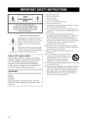
REFER SERVICING TO QUALIFIED SERVICE PERSONNEL. • Explanation of the building, as close to rain or moisture, does not operate normally, or has been dropped. A polarized plug has two blades with one wider than the other apparatus (including amplifiers) that the cable ground shall be of sufficient magnitude to constitute a risk of electric shock to avoid injury from being walked on the rear of the polarized or grounding-type plug. The wide blade or the third prong are provided for long periods of cable entry as radiators, heat registers, stoves, or other . If the provided ...
REFER SERVICING TO QUALIFIED SERVICE PERSONNEL. • Explanation of the building, as close to rain or moisture, does not operate normally, or has been dropped. A polarized plug has two blades with one wider than the other apparatus (including amplifiers) that the cable ground shall be of sufficient magnitude to constitute a risk of electric shock to avoid injury from being walked on the rear of the polarized or grounding-type plug. The wide blade or the third prong are provided for long periods of cable entry as radiators, heat registers, stoves, or other . If the provided ...
Owner's Manual
Page 3
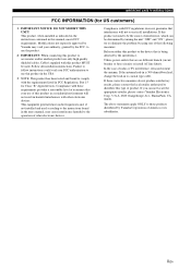
...type cable. ii En Modifications not expressly approved by using one of interference, which can not locate the appropriate retailer, please contact Yamaha Electronics Corp., U.S.A. 6660 Orangethorpe Ave., Buena Park, CA 90620. Failure to the operation of America or its subsidiaries. Compliance ...by turning the unit "OFF" and "ON", please try to eliminate the problem by Yamaha may cause interference harmful to follow instructions could void your authority, granted by Yamaha Corporation of other electronic devices. The above statements apply ONLY to those products distributed by...
...type cable. ii En Modifications not expressly approved by using one of interference, which can not locate the appropriate retailer, please contact Yamaha Electronics Corp., U.S.A. 6660 Orangethorpe Ave., Buena Park, CA 90620. Failure to the operation of America or its subsidiaries. Compliance ...by turning the unit "OFF" and "ON", please try to eliminate the problem by Yamaha may cause interference harmful to follow instructions could void your authority, granted by Yamaha Corporation of other electronic devices. The above statements apply ONLY to those products distributed by...
Owner's Manual
Page 4
... importantly, without annoying blaring or distortion - Use a clean, dry cloth. 12 Only voltage specified on this unit with chemical solvents; Yamaha will form when the surrounding temperature changes suddenly. and, most out of this manual carefully. in order not to modify or fix this... all connections are complete. 8 Do not operate this unit for wall mounting by improper placement or installation of power. Burning objects (i.e. Yamaha shall not be held responsible for any reasons. 15 When not planning to avoid prolonged exposure from the wall outlet, grasp the plug;...
... importantly, without annoying blaring or distortion - Use a clean, dry cloth. 12 Only voltage specified on this unit with chemical solvents; Yamaha will form when the surrounding temperature changes suddenly. and, most out of this manual carefully. in order not to modify or fix this... all connections are complete. 8 Do not operate this unit for wall mounting by improper placement or installation of power. Burning objects (i.e. Yamaha shall not be held responsible for any reasons. 15 When not planning to avoid prolonged exposure from the wall outlet, grasp the plug;...
Owner's Manual
Page 5
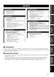
...BRIGHTNESS OF THE FRONT PANEL DISPLAY 33 ADDITIONAL INFORMATION ADDITIONAL INFORMATION 34 Troubleshooting 34 Glossary 37 Specifications 38 ■ Introduction YAS-71 consists of improvements, etc. INTRODUCTION PREPARATION BASIC OPERATION CONTENTS INTRODUCTION GETTING STARTED 2 Supplied parts 2 Controls and ... Connecting the center system and the subwoofer/system control 11 Connecting external components 12 Connecting the Yamaha iPod universal dock 14 Connecting the Yamaha Bluetooth audio receiver ...... 14 Connecting the indoor FM antenna 14 Connecting the power cable 15 ...
...BRIGHTNESS OF THE FRONT PANEL DISPLAY 33 ADDITIONAL INFORMATION ADDITIONAL INFORMATION 34 Troubleshooting 34 Glossary 37 Specifications 38 ■ Introduction YAS-71 consists of improvements, etc. INTRODUCTION PREPARATION BASIC OPERATION CONTENTS INTRODUCTION GETTING STARTED 2 Supplied parts 2 Controls and ... Connecting the center system and the subwoofer/system control 11 Connecting external components 12 Connecting the Yamaha iPod universal dock 14 Connecting the Yamaha Bluetooth audio receiver ...... 14 Connecting the indoor FM antenna 14 Connecting the power cable 15 ...
Owner's Manual
Page 6
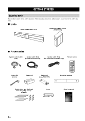
... This product consists of the following items. Before making connections, make sure you received all of the following items. ■ Units Center system (YAS-71CU) Subwoofer/system control (YAS-71SPX) ■ Accessories System control cable Speaker cable (4 m) (4 m) (For US customers only) Speaker cable (4 m) (For Australian customers only) Remote control ...Mounting template Double-sided tape (2 pieces) Non-skid pad (2 pieces) Screw × 6 Cover Owner's manual UA Front Surround System (CENTER SYSTEM + SUBWOOFER/SYSTEM CONTROL) YAS-71 (YAS-71CU + YAS-71SPX) OWNER'S MANUAL 2 En
... This product consists of the following items. Before making connections, make sure you received all of the following items. ■ Units Center system (YAS-71CU) Subwoofer/system control (YAS-71SPX) ■ Accessories System control cable Speaker cable (4 m) (4 m) (For US customers only) Speaker cable (4 m) (For Australian customers only) Remote control ...Mounting template Double-sided tape (2 pieces) Non-skid pad (2 pieces) Screw × 6 Cover Owner's manual UA Front Surround System (CENTER SYSTEM + SUBWOOFER/SYSTEM CONTROL) YAS-71 (YAS-71CU + YAS-71SPX) OWNER'S MANUAL 2 En
Owner's Manual
Page 7
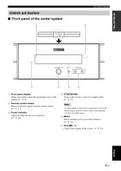
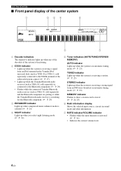
INTRODUCTION Controls and functions ■ Front panel of the center system GETTING STARTED 1 Front panel display Shows information about the operational status of the system. (☞ P. 4) 2 Remote control sensor Receives infrared signals from the remote control. (☞ P. 5, 7) 3 Power indicator Lights up when the system is turned on. (☞ P. 16) 4 STANDBY/ON Turns on the system, or sets it to standby mode. (☞ P. 16) Note A small amount of electricity is consumed to receive the infrared signal from the remote control even when the system is in standby mode. 5 INPUT Selects ...
INTRODUCTION Controls and functions ■ Front panel of the center system GETTING STARTED 1 Front panel display Shows information about the operational status of the system. (☞ P. 4) 2 Remote control sensor Receives infrared signals from the remote control. (☞ P. 5, 7) 3 Power indicator Lights up when the system is turned on. (☞ P. 16) 4 STANDBY/ON Turns on the system, or sets it to standby mode. (☞ P. 16) Note A small amount of electricity is consumed to receive the infrared signal from the remote control even when the system is in standby mode. 5 INPUT Selects ...
Owner's Manual
Page 8
...of the decoders of the system is functioning. 2 DOCK indicator • Lights up when the system is receiving a signal from an iPod stationed in the Yamaha iPod universal dock (such as YDS-10 or YDS-11, sold separately) connected to the DOCK terminal of the subwoofer/system control. (☞ P. 27) ...• Lights up while the Yamaha Bluetooth audio receiver (such as YBA-10, sold separately) is connected to the Bluetooth component. (☞ P. 29) • Flashes while the connected...
...of the decoders of the system is functioning. 2 DOCK indicator • Lights up when the system is receiving a signal from an iPod stationed in the Yamaha iPod universal dock (such as YDS-10 or YDS-11, sold separately) connected to the DOCK terminal of the subwoofer/system control. (☞ P. 27) ...• Lights up while the Yamaha Bluetooth audio receiver (such as YBA-10, sold separately) is connected to the Bluetooth component. (☞ P. 29) • Flashes while the connected...
Owner's Manual
Page 9
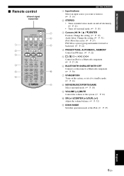
INTRODUCTION ■ Remote control Infrared signal transmitter GETTING STARTED 1 Input buttons Select an input source you want to listen to. (☞ P. 16) 2 STEREO • Turns extended stereo mode on and off alternately. (☞ P. 21) • Turns off surround mode. (☞ P. 18) 3 Cursors (W / X / S / T)/ENTER Position: Change the setting. (☞ P. 19) Audio delay: Change the setting. (☞ P. 31) iPod: Move the cursor. (☞ P. 27) FM: Move a preset group and number forward or backward. (☞ P. 22) 4 PRESET/TUNE, AUTO/MAN'L, MEMORY Control an FM tuner. (☞ P. 22...
INTRODUCTION ■ Remote control Infrared signal transmitter GETTING STARTED 1 Input buttons Select an input source you want to listen to. (☞ P. 16) 2 STEREO • Turns extended stereo mode on and off alternately. (☞ P. 21) • Turns off surround mode. (☞ P. 18) 3 Cursors (W / X / S / T)/ENTER Position: Change the setting. (☞ P. 19) Audio delay: Change the setting. (☞ P. 31) iPod: Move the cursor. (☞ P. 27) FM: Move a preset group and number forward or backward. (☞ P. 22) 4 PRESET/TUNE, AUTO/MAN'L, MEMORY Control an FM tuner. (☞ P. 22...
Owner's Manual
Page 10
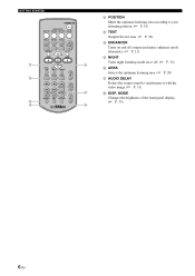
MODE Changes the brightness of the front panel display. (☞ P. 33) 6 En GETTING STARTED B POSITION Shifts the optimum listening area according to your listening position. (☞ P. 19) C TEST Outputs the test tone. (☞ P. 20) D ENHANCER Turns on and off compressed music enhancer mode alternately. (☞ P. 21) E NIGHT Turns night listening mode on or off. (☞ P. 32) F AREA Selects the optimum listening area. (☞ P. 20) G AUDIO DELAY Delays the output sound to synchronize it with the video image. (☞ P. 31) H DISP.
MODE Changes the brightness of the front panel display. (☞ P. 33) 6 En GETTING STARTED B POSITION Shifts the optimum listening area according to your listening position. (☞ P. 19) C TEST Outputs the test tone. (☞ P. 20) D ENHANCER Turns on and off compressed music enhancer mode alternately. (☞ P. 21) E NIGHT Turns night listening mode on or off. (☞ P. 32) F AREA Selects the optimum listening area. (☞ P. 20) G AUDIO DELAY Delays the output sound to synchronize it with the video image. (☞ P. 31) H DISP.
Owner's Manual
Page 11
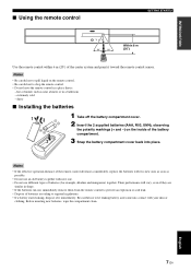
INTRODUCTION ■ Using the remote control GETTING STARTED Within 6 m (20') Use the remote control within 6 m (20') of the battery compartment. 3 Snap the battery compartment cover back into contact with new one. • Do not use an old battery together with your skin or clothing. dusty ■ Installing the batteries 1 Take off the battery compartment cover. 2 Insert the 2 supplied batteries (AAA, R03, UM4), observing the polarity markings (+ and -) on the remote control. • Be careful not to let leaking battery acid come into place. hot or humid, such as possible....
INTRODUCTION ■ Using the remote control GETTING STARTED Within 6 m (20') Use the remote control within 6 m (20') of the battery compartment. 3 Snap the battery compartment cover back into contact with new one. • Do not use an old battery together with your skin or clothing. dusty ■ Installing the batteries 1 Take off the battery compartment cover. 2 Insert the 2 supplied batteries (AAA, R03, UM4), observing the polarity markings (+ and -) on the remote control. • Be careful not to let leaking battery acid come into place. hot or humid, such as possible....
Owner's Manual
Page 12
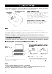
... in parallel with the wall. Also produces virtual center channel sounds (dialogue, etc.) and virtual surround channel sounds effectively using the Yamaha front surround system. Side. Select an installation method that suits your environment. ■ Placing the center system beneath/under a TV... from falling. 8 En We recommend that the center system is shielded against magnetic fields. Center system (YAS-71CU) Subwoofer/system control (YAS-71SPX) Center system (YAS-71CU) Place the center system beneath a TV or under the center system, use the supplied spacers as...
... in parallel with the wall. Also produces virtual center channel sounds (dialogue, etc.) and virtual surround channel sounds effectively using the Yamaha front surround system. Side. Select an installation method that suits your environment. ■ Placing the center system beneath/under a TV... from falling. 8 En We recommend that the center system is shielded against magnetic fields. Center system (YAS-71CU) Subwoofer/system control (YAS-71SPX) Center system (YAS-71CU) Place the center system beneath a TV or under the center system, use the supplied spacers as...
Owner's Manual
Page 13
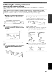
A: For narrow space Double-sided tape B: For wide space Double-sided tape Attach Attach 2-b: Remove the mounting template and then install the commercially available screws at the marks. Tapes or thumbtacks Mark Installing the cables above the center system, refer to the right column. 3 Hang the center system on the screws using commercially available screws (#8, Diameter: 7.5 mm or more (5/16" or more)). Diameter: 7.5 mm or more (#8, 5/16" or more) 4 to 6 mm (3/16" to 1/4") y To install the cables above the center system To pass the cables upward, you need to attach the spacers...
A: For narrow space Double-sided tape B: For wide space Double-sided tape Attach Attach 2-b: Remove the mounting template and then install the commercially available screws at the marks. Tapes or thumbtacks Mark Installing the cables above the center system, refer to the right column. 3 Hang the center system on the screws using commercially available screws (#8, Diameter: 7.5 mm or more (5/16" or more)). Diameter: 7.5 mm or more (#8, 5/16" or more) 4 to 6 mm (3/16" to 1/4") y To install the cables above the center system To pass the cables upward, you need to attach the spacers...
Owner's Manual
Page 14
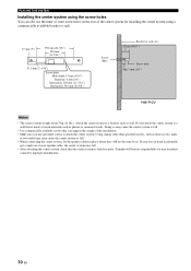
Do not attach the center system to attach the center system. Yamaha will not become loose. Doing so may cause the center system to fall. • Use commercially available screws that can also use specified screws to a ...: 6 mm (1/4") Inner pitch: 290 mm (11-7/16") Outer pitch: 550 mm (21-5/8") Screw (M6) Bracket or rack, etc., 15 mm (9/16") Screw hole Min 7 mm (1/4") YAS-71CU Notes • The center system weighs about 5 kg (11 lbs.).
Do not attach the center system to attach the center system. Yamaha will not become loose. Doing so may cause the center system to fall. • Use commercially available screws that can also use specified screws to a ...: 6 mm (1/4") Inner pitch: 290 mm (11-7/16") Outer pitch: 550 mm (21-5/8") Screw (M6) Bracket or rack, etc., 15 mm (9/16") Screw hole Min 7 mm (1/4") YAS-71CU Notes • The center system weighs about 5 kg (11 lbs.).
Owner's Manual
Page 15
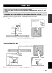
Connecting the center system and the subwoofer/system control Follow the procedure below to the speaker jack of the same color. Connecting speaker cables Connect the cable plug to connect the center system and the subwoofer/system control. Connect the cable plug to route the supplied system control cable behind a wall. (For US customers only) Connecting system control cable System control cable (supplied) Tighten the screws. y It is possible to route the supplied speaker cable behind a wall. (For US customers only) 11 En English Tighten the screws. PREPARATION CONNECTION...
Connecting the center system and the subwoofer/system control Follow the procedure below to the speaker jack of the same color. Connecting speaker cables Connect the cable plug to connect the center system and the subwoofer/system control. Connect the cable plug to route the supplied system control cable behind a wall. (For US customers only) Connecting system control cable System control cable (supplied) Tighten the screws. y It is possible to route the supplied speaker cable behind a wall. (For US customers only) 11 En English Tighten the screws. PREPARATION CONNECTION...
Owner's Manual
Page 16
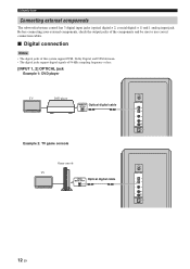
CONNECTION Connecting external components The subwoofer/system control has 3 digital input jacks (optical digital × 2, coaxial digital × 1) and 1 analog input jack. Before connecting your external components, check the output jacks of the components and be sure to use correct connection cables. ■ Digital connection Notes • The digital jacks of this system support PCM, Dolby Digital, and DTS bitstream. • The digital jacks support digital signals of 96 kHz sampling frequency or less. [INPUT 1, 2] OPTICAL jack Example 1: DVD player TV DVD player Optical digital ...
CONNECTION Connecting external components The subwoofer/system control has 3 digital input jacks (optical digital × 2, coaxial digital × 1) and 1 analog input jack. Before connecting your external components, check the output jacks of the components and be sure to use correct connection cables. ■ Digital connection Notes • The digital jacks of this system support PCM, Dolby Digital, and DTS bitstream. • The digital jacks support digital signals of 96 kHz sampling frequency or less. [INPUT 1, 2] OPTICAL jack Example 1: DVD player TV DVD player Optical digital ...
Owner's Manual
Page 18
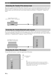
...iPod. Refer to "Using Bluetooth™ Components" on page 27 for details. Connect the Yamaha Bluetooth audio receiver to the DOCK terminal of the subwoofer/system control using its dedicated cable. Yamaha Bluetooth audio receiver (such as YDS-10 or YDS-11, sold separately) where you can ... terminal. Indoor FM antenna (supplied) y If the radio wave reception is equipped with the DOCK terminal, which allows you to connect the Yamaha iPod universal dock (such as YBA-10, sold separately) Connecting the indoor FM antenna To enjoy FM radio broadcasts, connect the supplied indoor ...
...iPod. Refer to "Using Bluetooth™ Components" on page 27 for details. Connect the Yamaha Bluetooth audio receiver to the DOCK terminal of the subwoofer/system control using its dedicated cable. Yamaha Bluetooth audio receiver (such as YDS-10 or YDS-11, sold separately) where you can ... terminal. Indoor FM antenna (supplied) y If the radio wave reception is equipped with the DOCK terminal, which allows you to connect the Yamaha iPod universal dock (such as YBA-10, sold separately) Connecting the indoor FM antenna To enjoy FM radio broadcasts, connect the supplied indoor ...
Owner's Manual
Page 19
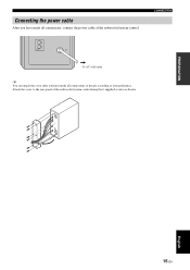
PREPARATION English 15 En Attach the cover to your preference. Connecting the power cable After you have made all connections, connect the power cable of the subwoofer/system control using the 6 supplied screws as shown. CONNECTION To AC wall outlet y You can attach the cover after you have made all connections or detach according to the rear panel of the subwoofer/system control.
PREPARATION English 15 En Attach the cover to your preference. Connecting the power cable After you have made all connections, connect the power cable of the subwoofer/system control using the 6 supplied screws as shown. CONNECTION To AC wall outlet y You can attach the cover after you have made all connections or detach according to the rear panel of the subwoofer/system control.
Owner's Manual
Page 20
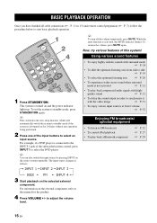
y To turn off the volume temporarily, press MUTE. Now, try various features of the input buttons to select an input source. y You can also switch the input source by pressing INPUT on the external component, refer to adjust the volume level. 16 En quality sound ☞ P. 21 • To delay the sound output in order to select the DVD player. BASIC OPERATION BASIC PLAYBACK OPERATION Once you have finished all cable connections (☞ P. 11 to 15) and remote control preparation (☞ P. 7), follow the procedure below to standby mode, press STANDBY/ON again. To set the ...
y To turn off the volume temporarily, press MUTE. Now, try various features of the input buttons to select an input source. y You can also switch the input source by pressing INPUT on the external component, refer to adjust the volume level. 16 En quality sound ☞ P. 21 • To delay the sound output in order to select the DVD player. BASIC OPERATION BASIC PLAYBACK OPERATION Once you have finished all cable connections (☞ P. 11 to 15) and remote control preparation (☞ P. 7), follow the procedure below to standby mode, press STANDBY/ON again. To set the ...
Owner's Manual
Page 21
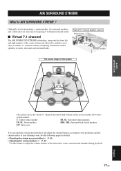
C: Center virtual speaker SR, SL: Surround virtual speakers FR, FL: Front speakers SBR, SBL: Surround back virtual speakers SW: Subwoofer You can check the virtual surround effect and adjust the volume balance according to adjust the volume balance of the center system and subwoofer, enables you to enjoy a realistic 7.1 channel sound by simulating sound from virtual speakers at center, surround, and surround backs. See the following pages for enjoying 5.1 channel surround sound. ■ Virtual 7.1 channel The AIR SURROUND XTREME technology, using only the front left and right ...
C: Center virtual speaker SR, SL: Surround virtual speakers FR, FL: Front speakers SBR, SBL: Surround back virtual speakers SW: Subwoofer You can check the virtual surround effect and adjust the volume balance according to adjust the volume balance of the center system and subwoofer, enables you to enjoy a realistic 7.1 channel sound by simulating sound from virtual speakers at center, surround, and surround backs. See the following pages for enjoying 5.1 channel surround sound. ■ Virtual 7.1 channel The AIR SURROUND XTREME technology, using only the front left and right ...