
Owner's Manual
Page 2
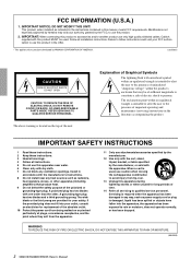
...accordance with the manufacturer's instructions. 8 Do not install near water. 6 Clean only with the apparatus. Modifications not expressly approved by Yamaha may be used , use only high quality shielded cables. A polarized plug has two blades with this apparatus near any ventilation openings. A grounding...BACK). WARNING TO REDUCE THE RISK OF FIRE OR ELECTRIC SHOCK, DO NOT EXPOSE THIS APPARATUS TO RAIN OR MOISTURE. (98-6500) 2 XM4180/XM4080/XH200 Owner's Manual The above warning is intended to alert the user to persons. When a cart is damaged, liquid has been spilled or...
...accordance with the manufacturer's instructions. 8 Do not install near water. 6 Clean only with the apparatus. Modifications not expressly approved by Yamaha may be used , use only high quality shielded cables. A polarized plug has two blades with this apparatus near any ventilation openings. A grounding...BACK). WARNING TO REDUCE THE RISK OF FIRE OR ELECTRIC SHOCK, DO NOT EXPOSE THIS APPARATUS TO RAIN OR MOISTURE. (98-6500) 2 XM4180/XM4080/XH200 Owner's Manual The above warning is intended to alert the user to persons. When a cart is damaged, liquid has been spilled or...
Owner's Manual
Page 3
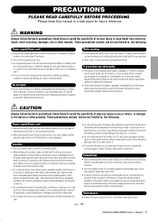
.... Water warning • Do not expose the device to prevent the internal temperature from the AC outlet when cleaning the device. (5)-4 1/2 XM4180/XM4080/XH200 Owner's Manual 3 1 If this device should be dropped or damaged, immediately turn off for all devices, set all connected cables. ... is easily accessible. This device has ventilation holes at the sides, 10cm behind and 10cm above. Pulling by qualified Yamaha service personnel. Inadequate ventilation can damage it inspected by the cord can result in overheating, possibly causing damage to the device(s), ...
.... Water warning • Do not expose the device to prevent the internal temperature from the AC outlet when cleaning the device. (5)-4 1/2 XM4180/XM4080/XH200 Owner's Manual 3 1 If this device should be dropped or damaged, immediately turn off for all devices, set all connected cables. ... is easily accessible. This device has ventilation holes at the sides, 10cm behind and 10cm above. Pulling by qualified Yamaha service personnel. Inadequate ventilation can damage it inspected by the cord can result in overheating, possibly causing damage to the device(s), ...
Owner's Manual
Page 4
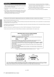
... electricity is still flowing to the device at a high or uncomfortable volume level, since this can be made simply and without problem. 4 XM4180/XM4080/XH200 Owner's Manual (5)-4 2/2 2 IMPORTANT NOTICE FOR THE UNITED KINGDOM Connecting the Plug and Cord WARNING: THIS APPARATUS MUST BE EARTHED IMPORTANT. If... only, and may not correspond with the letter L or coloured RED. • This applies only to products distributed by qualified Yamaha service personnel. • Do not use leads or a cord that have been manufactured in such a way that is lost or destroyed. ...
... electricity is still flowing to the device at a high or uncomfortable volume level, since this can be made simply and without problem. 4 XM4180/XM4080/XH200 Owner's Manual (5)-4 2/2 2 IMPORTANT NOTICE FOR THE UNITED KINGDOM Connecting the Plug and Cord WARNING: THIS APPARATUS MUST BE EARTHED IMPORTANT. If... only, and may not correspond with the letter L or coloured RED. • This applies only to products distributed by qualified Yamaha service personnel. • Do not use leads or a cord that have been manufactured in such a way that is lost or destroyed. ...

Owner's Manual
Page 5
... and trouble-free operation, please read this amplifier from Yamaha's wealth of circuit design. Main features include On the XM4180/XM4080: • Four separate amplifier sections allows the unit ...and stability, guaranteeing the highest possible audio performance. Contents Controls and Functions 6 Front Panel 6 Rear Panel (XM4180/XM4080 7 Rear Panel (XH200 10 Connection 11 Using a Euroblock connector 11 Speaker Connection 12 Troubleshooting 12 Specifications 13 ... device. Introduction Thank you for purchasing a Yamaha XM4180, XM4080 or XH200 Power Amplifier.
... and trouble-free operation, please read this amplifier from Yamaha's wealth of circuit design. Main features include On the XM4180/XM4080: • Four separate amplifier sections allows the unit ...and stability, guaranteeing the highest possible audio performance. Contents Controls and Functions 6 Front Panel 6 Rear Panel (XM4180/XM4080 7 Rear Panel (XH200 10 Connection 11 Using a Euroblock connector 11 Speaker Connection 12 Troubleshooting 12 Specifications 13 ... device. Introduction Thank you for purchasing a Yamaha XM4180, XM4080 or XH200 Power Amplifier.
Owner's Manual
Page 6
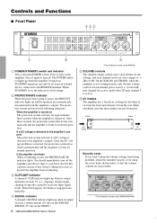
...operation. Make absolutely sure that the volume controls are inaccessible. * The illustration shows model XM4180/XM4080. 4 Press to turn on the XH200.) 6 XM4180/XM4080/XH200 Owner's Manual 5 * The illustration shows model XM4180. 5 VOLUME controls The channel volume controls have click detents for the settings, and each...STANDBY switch and indicator This is active, the PROTECT indicator lights up when its output exceeds a certain amount (2V rms on the XM4180/ XM4080, 4V rms on the amplifier. STANDBY operation can be set over a range of this happens, the limiter is turned on...
...operation. Make absolutely sure that the volume controls are inaccessible. * The illustration shows model XM4180/XM4080. 4 Press to turn on the XH200.) 6 XM4180/XM4080/XH200 Owner's Manual 5 * The illustration shows model XM4180. 5 VOLUME controls The channel volume controls have click detents for the settings, and each...STANDBY switch and indicator This is active, the PROTECT indicator lights up when its output exceeds a certain amount (2V rms on the XM4180/ XM4080, 4V rms on the amplifier. STANDBY operation can be set over a range of this happens, the limiter is turned on...
Owner's Manual
Page 7
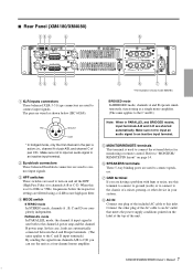
... the external device for channels A-B or C-D. Connect the other device in PARALLEL and BRIDGED modes, input terminals A-B and C-D are shorted automatically. XM4180/XM4080/XH200 Owner's Manual 7 5 i.e., channel A of pair A/B, and channel C of the included AC cable to this case, loads are used to... connect input signals. ■ Rear Panel (XM4180/XM4080) 13 2 4 6 13 2 4 5 6 78 * The illustration shows model XM4180. 1 XLR inputs connectors These balanced XLR-3-31 type connectors are used to turn on and off the HPF ...
... the external device for channels A-B or C-D. Connect the other device in PARALLEL and BRIDGED modes, input terminals A-B and C-D are shorted automatically. XM4180/XM4080/XH200 Owner's Manual 7 5 i.e., channel A of pair A/B, and channel C of the included AC cable to this case, loads are used to... connect input signals. ■ Rear Panel (XM4180/XM4080) 13 2 4 6 13 2 4 5 6 78 * The illustration shows model XM4180. 1 XLR inputs connectors These balanced XLR-3-31 type connectors are used to turn on and off the HPF ...
Owner's Manual
Page 8
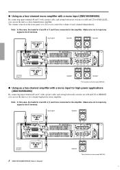
Make sure not to input any signal to the D terminal. ● Using as a four-channel mono amplifier with a mono input (XM4180/XM4080) By connecting input terminals B and C with a proper cable, and setting both mode switches for A/B and C/D to PARALLEL, you can use the unit as ... controls on the front panel (A to D) let you can use the unit as a two-channel amplifier with a mono input for high-power applications (XM4180/XM4080) By connecting input terminals B and C with a proper cable, and setting both mode switches for A and B or C and D are connected in the ampli&#...
Make sure not to input any signal to the D terminal. ● Using as a four-channel mono amplifier with a mono input (XM4180/XM4080) By connecting input terminals B and C with a proper cable, and setting both mode switches for A/B and C/D to PARALLEL, you can use the unit as ... controls on the front panel (A to D) let you can use the unit as a two-channel amplifier with a mono input for high-power applications (XM4180/XM4080) By connecting input terminals B and C with a proper cable, and setting both mode switches for A and B or C and D are connected in the ampli&#...
Owner's Manual
Page 9
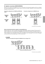
... a rated input of 10 W (100 W) and ten speakers with a total rated speaker input of 300 W as shown below . XM4180/XM4080/XH200 Owner's Manual 9 7 The XM4180 can be connected to the amplifier in parallel fashion multiple high-impedance speakers that speaker impedance will vary according to the... connection method and the number of speakers. ● Speaker connections (XM4180/XM4080) Speakers can be connected to speakers with a total rated input of up to 300 W. Connection configurations for STEREO and...
... a rated input of 10 W (100 W) and ten speakers with a total rated speaker input of 300 W as shown below . XM4180/XM4080/XH200 Owner's Manual 9 7 The XM4180 can be connected to the amplifier in parallel fashion multiple high-impedance speakers that speaker impedance will vary according to the... connection method and the number of speakers. ● Speaker connections (XM4180/XM4080) Speakers can be connected to speakers with a total rated input of up to 300 W. Connection configurations for STEREO and...
Owner's Manual
Page 10
... enables you can connect up to ten speakers 10W 10W 10W Rated input 10W 10W 10W 10 W x 20 speakers (200W) 10 W x 20 speakers (200W) 10 XM4180/XM4080/XH200 Owner's Manual 8 You can connect speakers with a rated input of speakers that support 70V or 100V line output. excessive levels at the top of...
... enables you can connect up to ten speakers 10W 10W 10W Rated input 10W 10W 10W 10 W x 20 speakers (200W) 10 W x 20 speakers (200W) 10 XM4180/XM4080/XH200 Owner's Manual 8 You can connect speakers with a rated input of speakers that support 70V or 100V line output. excessive levels at the top of...
Owner's Manual
Page 11
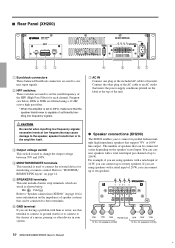
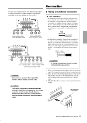
... also connect speakers with different rated inputs to different channels or connect speakers with different rated input to the same channel, as the Yamaha ST15). Use a ferrule whose conductor portion has an external diameter of 1.6 mm or less, and a length of the cable or... transformer to use speakers that you use ferrules with insulation sleeves. You cannot connect a low-impedance speaker directly to fix the wires. -G + XM4180/XM4080/XH200 Owner's Manual 11 9 When rack-mounting your equipment, use a speaker transformer (such as shown below: 10W 10W 10W 10 W x 20 ...
... also connect speakers with different rated inputs to different channels or connect speakers with different rated input to the same channel, as the Yamaha ST15). Use a ferrule whose conductor portion has an external diameter of 1.6 mm or less, and a length of the cable or... transformer to use speakers that you use ferrules with insulation sleeves. You cannot connect a low-impedance speaker directly to fix the wires. -G + XM4180/XM4080/XH200 Owner's Manual 11 9 When rack-mounting your equipment, use a speaker transformer (such as shown below: 10W 10W 10W 10 W x 20 ...
Owner's Manual
Page 12
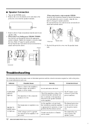
... the terminal as the protective circuit operation in the wiring. The thermal protection circuit activates to protect the speaker system. 12 XM4180/XM4080/XH200 Owner's Manual 10 Chassis Bare wire * Actual size Speaker cable Wire should not touch the chassis. 5 Reattach the...polarities. PROTECT/ MUTE indicator lights up There is appropriate for operation, as suggested in the appropriate speaker terminals. Consult your dealer or a Yamaha service center. A DC voltage of ±2 V or greater was detected in the illustration, and tighten the screw to securely clamp the...
... the terminal as the protective circuit operation in the wiring. The thermal protection circuit activates to protect the speaker system. 12 XM4180/XM4080/XH200 Owner's Manual 10 Chassis Bare wire * Actual size Speaker cable Wire should not touch the chassis. 5 Reattach the...polarities. PROTECT/ MUTE indicator lights up There is appropriate for operation, as suggested in the appropriate speaker terminals. Consult your dealer or a Yamaha service center. A DC voltage of ±2 V or greater was detected in the illustration, and tighten the screw to securely clamp the...
Owner's Manual
Page 13
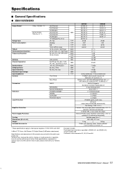
... MIN TYP TYP TYP TYP MAX MAX MAX TYP MIN MIN MIN MAX MIN TYP MIN TYP XM4180 210 W x 4 250 W x 4 500 W x 2 180 W x 4 230 W x 4 460 W x 2 300 W x 2 30 dB 5 W 40 W 600 W 0.1 % 0.1 % 0 dB 0 dB -0.5 dB 103 dB XM4080 90 W x 4 120 W x 4 240 W x 2 80 W x 4 115W x 4 230W x 2 - 26 dB 5 W 40...;ed in every locale, please check with your Yamaha dealer. operation restored automatically. reserves the right to Environments: E1, E2, E3 and E4 XM4180/XM4080/XH200 Owner's Manual 13 41 Specifications ■ General Specifications ● XM4180/XM4080 Output Power* 1 kHz, THD+N= 1 % ...
... MIN TYP TYP TYP TYP MAX MAX MAX TYP MIN MIN MIN MAX MIN TYP MIN TYP XM4180 210 W x 4 250 W x 4 500 W x 2 180 W x 4 230 W x 4 460 W x 2 300 W x 2 30 dB 5 W 40 W 600 W 0.1 % 0.1 % 0 dB 0 dB -0.5 dB 103 dB XM4080 90 W x 4 120 W x 4 240 W x 2 80 W x 4 115W x 4 230W x 2 - 26 dB 5 W 40...;ed in every locale, please check with your Yamaha dealer. operation restored automatically. reserves the right to Environments: E1, E2, E3 and E4 XM4180/XM4080/XH200 Owner's Manual 13 41 Specifications ■ General Specifications ● XM4180/XM4080 Output Power* 1 kHz, THD+N= 1 % ...
Owner's Manual
Page 14
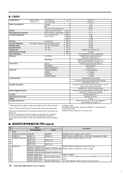
...input 600 Ω shunt Att. operation restored automatically. Thermal: Power supply shutdown (when temp. ≥ 90 °C); Yamaha Corp. Since specifications, equipment or options may not be the same in EN55103-1 and EN55103-2. operation not restored ...E1, E2, E3 and E4 ■ MONITOR/REMOTE PIN layout Pin No. 1 GND Signal XM4180/XM4080 XH200 Description 2 REMOTE CONTROL STANDBY 3 MONITOR MODEL ID STANDBY MODEL ID STANDBY Control: Supply 5 VDC, 5 mADC XM4180: 560 Ω, XM4080: 680 Ω, XH200: 820 Ω (Impedance to rated power supplies of 120V, 230V...
...input 600 Ω shunt Att. operation restored automatically. Thermal: Power supply shutdown (when temp. ≥ 90 °C); Yamaha Corp. Since specifications, equipment or options may not be the same in EN55103-1 and EN55103-2. operation not restored ...E1, E2, E3 and E4 ■ MONITOR/REMOTE PIN layout Pin No. 1 GND Signal XM4180/XM4080 XH200 Description 2 REMOTE CONTROL STANDBY 3 MONITOR MODEL ID STANDBY MODEL ID STANDBY Control: Supply 5 VDC, 5 mADC XM4180: 560 Ω, XM4080: 680 Ω, XH200: 820 Ω (Impedance to rated power supplies of 120V, 230V...
Owner's Manual
Page 15
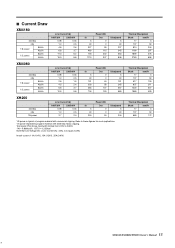
... that Line Voltage [V] x Line Current [A] = [VA], not equals to these figures for most applications. 1/3 power represents program material with occasional clipping. ■ Current Draw XM4180 standby idle 1/8 power 8Ω/ch 4Ω/ch 1/3 power 8Ω/ch 4Ω/ch Line Current (A) 100/120V 230/240V 0.08 0.04 1.0 0.5 4.8 2.6 6.8 3.7 11.3 6.2 15.9 8.8 In... Btu/h kcal/h 17 4 137 34 517 130 837 211 1220 307 1980 499 Thermal Dissipation Btu/h kcal/h 17 4 137 34 683 172 XM4180/XM4080/XH200 Owner's Manual 15 43 Refer to [W].
... that Line Voltage [V] x Line Current [A] = [VA], not equals to these figures for most applications. 1/3 power represents program material with occasional clipping. ■ Current Draw XM4180 standby idle 1/8 power 8Ω/ch 4Ω/ch 1/3 power 8Ω/ch 4Ω/ch Line Current (A) 100/120V 230/240V 0.08 0.04 1.0 0.5 4.8 2.6 6.8 3.7 11.3 6.2 15.9 8.8 In... Btu/h kcal/h 17 4 137 34 517 130 837 211 1220 307 1980 499 Thermal Dissipation Btu/h kcal/h 17 4 137 34 683 172 XM4180/XM4080/XH200 Owner's Manual 15 43 Refer to [W].
Owner's Manual
Page 17
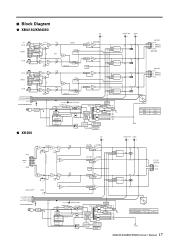
...MODE SW STEREO BRIDGE PARALLEL CH C CH D INV STEREO BRIDGE PARALLEL MODE SW STEREO BRIDGE PARALLEL CLIP x4 RE [+14dBu] LIMITER XM4180[+34dBu] XM4080[+30dBu] PA LIMITER PA TEMP LIMITER PA LIMITER PA PROTECTION x4 RE SIGNAL x4 GR DC MUTE PS PROTECTION TEMP DC MUTE PS ...PROTECTION TEMP DC MUTE PS PROTECTION TEMP DC MUTE PS PROTECTION TEMP OUTPUT CH A (+) BRIDGE (-) BRIDGE CH B XM4180[+34dBu] XM4080[+30dBu] OUTPUT CH C (+) BRIDGE (-) BRIDGE CH D GR/OR (GR+RE) POWER SW POWER/STANDBY SUB TRANS +15V MAIN TRANS RELAY DRIVE J,H,B,W,K,C ...
...MODE SW STEREO BRIDGE PARALLEL CH C CH D INV STEREO BRIDGE PARALLEL MODE SW STEREO BRIDGE PARALLEL CLIP x4 RE [+14dBu] LIMITER XM4180[+34dBu] XM4080[+30dBu] PA LIMITER PA TEMP LIMITER PA LIMITER PA PROTECTION x4 RE SIGNAL x4 GR DC MUTE PS PROTECTION TEMP DC MUTE PS ...PROTECTION TEMP DC MUTE PS PROTECTION TEMP DC MUTE PS PROTECTION TEMP OUTPUT CH A (+) BRIDGE (-) BRIDGE CH B XM4180[+34dBu] XM4080[+30dBu] OUTPUT CH C (+) BRIDGE (-) BRIDGE CH D GR/OR (GR+RE) POWER SW POWER/STANDBY SUB TRANS +15V MAIN TRANS RELAY DRIVE J,H,B,W,K,C ...