
Owner's Manual
Page 3
... from excessive volume levels. The digital device component may cause interference harmful to use only high quality shielded cables. Failure to follow instructions could void your FCC authorization to the operation of interference, which can not locate the appropriate retailer, please contact Yamaha Electronics Corp., U.S.A. 6660 Orangethorpe Ave, Buena Park, CA 90620. Utilize power outlets that lets the sound come through...
... from excessive volume levels. The digital device component may cause interference harmful to use only high quality shielded cables. Failure to follow instructions could void your FCC authorization to the operation of interference, which can not locate the appropriate retailer, please contact Yamaha Electronics Corp., U.S.A. 6660 Orangethorpe Ave, Buena Park, CA 90620. Utilize power outlets that lets the sound come through...

Owner's Manual
Page 5
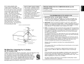
... cord. 11. Using this unit with a voltage other equipment. YAMAHA will not be set the VOLUME control to connecting or disconnecting cables. Retain this manual carefully. WARNING Do not change the IMPEDANCE SELECTOR switch setting while the power to qualified Yamaha service personnel. INSTALL THE UNIT IN WELL-VENTILATED CONDITION The openings on , otherwise this unit for long periods of time (ie., vacation, etc.), disconnect the AC power plug from use...
... cord. 11. Using this unit with a voltage other equipment. YAMAHA will not be set the VOLUME control to connecting or disconnecting cables. Retain this manual carefully. WARNING Do not change the IMPEDANCE SELECTOR switch setting while the power to qualified Yamaha service personnel. INSTALL THE UNIT IN WELL-VENTILATED CONDITION The openings on , otherwise this unit for long periods of time (ie., vacation, etc.), disconnect the AC power plug from use...

Owner's Manual
Page 6
... ROOM 2 REMOTE CONTROL UNIT 39 SPEAKER BALANCE ADJUSTMENT 41 ADJUSTMENTS IN THE "SET MENU" MODE 43 GENERAL OPERATION 46 PLAYING A SOURCE 46 RECORDING A SOURCE TO AUDIO/VIDEO TAPE (OR DUBBING FROM A TAPE TO ANOTHER 48 TUNING OPERATIONS 50 AUTOMATIC TUNING 50 MANUAL TUNING 50 PRESET TUNING 51 MANUAL PRESET TUNING 51 AUTOMATIC PRESET TUNING 52 EXCHANGING PRESET STATIONS 53 SELECTING SOUND FIELD PROGRAMS 54 CANCELING THE EFFECT SOUND 55 DESCRIPTIONS OF THE SOUND FIELD PROGRAMS 56 ADJUSTING DELAY TIME AND EACH SPEAKER OUTPUT LEVEL 59 SETTING THE SLEEP TIMER 61 REMOTE CONTROL UNIT...
... ROOM 2 REMOTE CONTROL UNIT 39 SPEAKER BALANCE ADJUSTMENT 41 ADJUSTMENTS IN THE "SET MENU" MODE 43 GENERAL OPERATION 46 PLAYING A SOURCE 46 RECORDING A SOURCE TO AUDIO/VIDEO TAPE (OR DUBBING FROM A TAPE TO ANOTHER 48 TUNING OPERATIONS 50 AUTOMATIC TUNING 50 MANUAL TUNING 50 PRESET TUNING 51 MANUAL PRESET TUNING 51 AUTOMATIC PRESET TUNING 52 EXCHANGING PRESET STATIONS 53 SELECTING SOUND FIELD PROGRAMS 54 CANCELING THE EFFECT SOUND 55 DESCRIPTIONS OF THE SOUND FIELD PROGRAMS 56 ADJUSTING DELAY TIME AND EACH SPEAKER OUTPUT LEVEL 59 SETTING THE SLEEP TIMER 61 REMOTE CONTROL UNIT...
Owner's Manual
Page 14
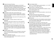
... 4 or 5 speaker system, the Digital Sound Field Processing is decoded with any or all channels, but the main speakers are used , if the source contains center-channel signals, dialog, vocals etc. When playing back a source with the DSP programs No. 1 through No. 4, or when the Dolby Digital (AC-3) is still performed, but also for reproducing the LFE (low frequency effect) sound with high fidelity when playing back a source with the Dolby Digital (AC-3) decoded...
... 4 or 5 speaker system, the Digital Sound Field Processing is decoded with any or all channels, but the main speakers are used , if the source contains center-channel signals, dialog, vocals etc. When playing back a source with the DSP programs No. 1 through No. 4, or when the Dolby Digital (AC-3) is still performed, but also for reproducing the LFE (low frequency effect) sound with high fidelity when playing back a source with the Dolby Digital (AC-3) decoded...

Owner's Manual
Page 18
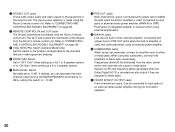
... output from the main speakers. 8 Master VOLUME Control Simultaneously controls volume level at the main left and right channels while maintaining overall tonal balance. If you will not use to the OFF position. A A/B/C/D/E Switch Press this unit) you will hear a click and a sound of the built-in fan rotating for the main speakers you do not have a subwoofer, the use of selected program lights up on the display panel. 6 Input Selector Buttons Selects an input source...
... output from the main speakers. 8 Master VOLUME Control Simultaneously controls volume level at the main left and right channels while maintaining overall tonal balance. If you will not use to the OFF position. A A/B/C/D/E Switch Press this unit) you will hear a click and a sound of the built-in fan rotating for the main speakers you do not have a subwoofer, the use of selected program lights up on the display panel. 6 Input Selector Buttons Selects an input source...

Owner's Manual
Page 19
... "AUTO TUNING" lights up on a mode of this unit, the number of the input selector buttons. For example, when the built-in the SET MENU mode. 15 English D BASS and TREBLE Controls Adjust low and high frequency response respectively for tuning. G REC OUT Selector Selects the source to be recorded to page 52 for details.) J TUNING DOWN/UP Button Used for the main channels only. During this period, select a desired preset station number by the tone control circuitry. O SET MENU Switch Whenever...
... "AUTO TUNING" lights up on a mode of this unit, the number of the input selector buttons. For example, when the built-in the SET MENU mode. 15 English D BASS and TREBLE Controls Adjust low and high frequency response respectively for tuning. G REC OUT Selector Selects the source to be recorded to page 52 for details.) J TUNING DOWN/UP Button Used for the main channels only. During this period, select a desired preset station number by the tone control circuitry. O SET MENU Switch Whenever...

Owner's Manual
Page 20
DISPLAY PANEL 12 3 4 PRESET ROOM 2 AM FM kHz MHz MEMORY TAPE 2 MONITOR STEREO AUTO TUNING SPEAKERS SPEAKERS ROOM 2 CONTROL A B 0 20 40 60 I00 DIGITAL ENHANCED 70 mm PCM DIGITAL DIGITAL DSP mS dB PRO LOGIC SLEEP 56 7 8 90 A B C 1 Preset Station Number Display Shows the selected preset station number (1 to 8) and its group (A to E). 2 ROOM 2 Indicator Lights up when you switch the input source for the second room by the corresponding input selector button and REC OUT selector. P Auxiliary Input Jacks (VIDEO AUX) Connect an auxiliary video or audio unit...
DISPLAY PANEL 12 3 4 PRESET ROOM 2 AM FM kHz MHz MEMORY TAPE 2 MONITOR STEREO AUTO TUNING SPEAKERS SPEAKERS ROOM 2 CONTROL A B 0 20 40 60 I00 DIGITAL ENHANCED 70 mm PCM DIGITAL DIGITAL DSP mS dB PRO LOGIC SLEEP 56 7 8 90 A B C 1 Preset Station Number Display Shows the selected preset station number (1 to 8) and its group (A to E). 2 ROOM 2 Indicator Lights up when you switch the input source for the second room by the corresponding input selector button and REC OUT selector. P Auxiliary Input Jacks (VIDEO AUX) Connect an auxiliary video or audio unit...

Owner's Manual
Page 21
.... 8 SPEAKERS A/B Indicators The indicator A or B which corresponds to the memory by using the A/B/C/D/E switch and the preset station number selector buttons. 6 AUTO TUNING Indicator Lights up when this unit, "PCM DIGITAL" lights up when the built-in digital sound field processor is received. 0 Signal-level Meter Indicates the signal level of selected source encoded with the Dolby Digital (AC-3) are input to this indicator flashes for about 5 seconds. "DSP" lights up when the built-in Dolby Pro Logic Surround Decoder is functioning...
.... 8 SPEAKERS A/B Indicators The indicator A or B which corresponds to the memory by using the A/B/C/D/E switch and the preset station number selector buttons. 6 AUTO TUNING Indicator Lights up when this unit, "PCM DIGITAL" lights up when the built-in digital sound field processor is received. 0 Signal-level Meter Indicates the signal level of selected source encoded with the Dolby Digital (AC-3) are input to this indicator flashes for about 5 seconds. "DSP" lights up when the built-in Dolby Pro Logic Surround Decoder is functioning...

Owner's Manual
Page 22
...;MIN./ SPEAKER I20V 60Hz I00W MAX. CONNECTIONS REAR PANEL PARTS AND THEIR FUNCTIONS Before you start making connections make sure all related electronic components are turned OFF. 12 3 4 5 67 8 90 FREQUENCY STEP FM AM 50kHz 9kHz I00kHz I0kHz AM ANT GND FM ANT 75Ω UNBAL. GND AUDIO SIGNAL PHONO 1 CD 3 TAPE PB TAPE(MD) 4 REC OUT PCM/ DIGITAL IN (AC-3 DIGITAL IN) DVD/LD TV/DBS COAXIAL AUDIO SIGNAL VIDEO SIGNAL OUTPUT VIDEO S VIDEO C CENTER C DVD/LD DVD/LD...
...;MIN./ SPEAKER I20V 60Hz I00W MAX. CONNECTIONS REAR PANEL PARTS AND THEIR FUNCTIONS Before you start making connections make sure all related electronic components are turned OFF. 12 3 4 5 67 8 90 FREQUENCY STEP FM AM 50kHz 9kHz I00kHz I0kHz AM ANT GND FM ANT 75Ω UNBAL. GND AUDIO SIGNAL PHONO 1 CD 3 TAPE PB TAPE(MD) 4 REC OUT PCM/ DIGITAL IN (AC-3 DIGITAL IN) DVD/LD TV/DBS COAXIAL AUDIO SIGNAL VIDEO SIGNAL OUTPUT VIDEO S VIDEO C CENTER C DVD/LD DVD/LD...
Owner's Manual
Page 23
... SPEAKERS Terminals When using the built-in front effect-channel amplifier, connect the front effect speakers here. 9 REAR SPEAKERS Terminals When using the built-in rear-channel amplifier, connect the rear speakers here. 0 VOLTAGE SELECTOR (General Model only) Be sure to set this switch to the position suitable for AC-3 discrete audio signals, connect the AC-3 RF output jack to the DVD/LD COAXIAL or OPTICAL jack of this unit from the AC outlet. 3 AUDIO SIGNAL Connection Jacks (for Audio Source Equipment) Connect the inputs...
... SPEAKERS Terminals When using the built-in front effect-channel amplifier, connect the front effect speakers here. 9 REAR SPEAKERS Terminals When using the built-in rear-channel amplifier, connect the rear speakers here. 0 VOLTAGE SELECTOR (General Model only) Be sure to set this switch to the position suitable for AC-3 discrete audio signals, connect the AC-3 RF output jack to the DVD/LD COAXIAL or OPTICAL jack of this unit from the AC outlet. 3 AUDIO SIGNAL Connection Jacks (for Audio Source Equipment) Connect the inputs...
Owner's Manual
Page 24
... OUTPUT Jacks Front-channel line output. Can be connected to the equipment in main-channel amplifier. C ROOM 2 OUT Jacks These jacks output audio and video signals to input jacks of an external stereo power amplifier driving the front effect speakers. 20 G MAIN LEVEL Switch Normally set to built-in the second room. H PRE OUT Jacks Main-channel line output. Connected with jumper bars to these jacks. Connected to input jacks of external stereo power amplifier (MAIN IN or TAPE PLAY jacks of integrated amplifier or receiver) when using two subwoofers, connect their amplifiers...
... OUTPUT Jacks Front-channel line output. Can be connected to the equipment in main-channel amplifier. C ROOM 2 OUT Jacks These jacks output audio and video signals to input jacks of an external stereo power amplifier driving the front effect speakers. 20 G MAIN LEVEL Switch Normally set to built-in the second room. H PRE OUT Jacks Main-channel line output. Connected with jumper bars to these jacks. Connected to input jacks of external stereo power amplifier (MAIN IN or TAPE PLAY jacks of integrated amplifier or receiver) when using two subwoofers, connect their amplifiers...

Owner's Manual
Page 35
... the rear panel are shown by the lighting of MAIN speakers, connect one set to the ON position. Selected main speakers are in place. It is desired. Connect the MAIN speakers to the speaker output terminals of MAIN speakers can be connected to this case, remove the jumper bars and connect the PRE OUT jacks to the INPUT jacks of MAIN speakers, connect them to connect the left and right channels correctly. Main speaker A Power amplifier INPUT PRE...
... the rear panel are shown by the lighting of MAIN speakers, connect one set to the ON position. Selected main speakers are in place. It is desired. Connect the MAIN speakers to the speaker output terminals of MAIN speakers can be connected to this case, remove the jumper bars and connect the PRE OUT jacks to the INPUT jacks of MAIN speakers, connect them to connect the left and right channels correctly. Main speaker A Power amplifier INPUT PRE...
Owner's Manual
Page 44
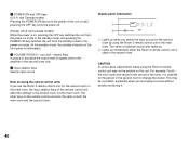
... OFF key switches the unit from the power-on mode to the standby mode, and pressing the POWER ON key switches the unit from the standby mode to the amplifier in both the main room and second room are taping a source without directly monitoring it is used in the second room to the tuner, it . 40 Display panel information 1 2 ROOM 2 ROOM 2 CONTROL SPEAKERS A 1 Lights up momentarily when the Room 2 remote control unit is...
... OFF key switches the unit from the power-on mode to the standby mode, and pressing the POWER ON key switches the unit from the standby mode to the amplifier in both the main room and second room are taping a source without directly monitoring it is used in the second room to the tuner, it . 40 Display panel information 1 2 ROOM 2 ROOM 2 CONTROL SPEAKERS A 1 Lights up momentarily when the Room 2 remote control unit is...

Owner's Manual
Page 45
... remote control unit. Adjust the master VOLUME to adjust the level of each speaker level. Center CENTER Right rear R SUR. Left rear Pressing the key changes the speaker in the reverse order. * If the CENTER SPEAKER mode is pressed, the speaker selection changes in turn (see diagram). Repeat step 3 and 4 to a normal listening level. * The state of test-tone output is shown on the display panel and the monitor screen. (On the monitor screen, it becomes almost as same as follows. Set the TIME/LEVEL·SET MENU switch...
... remote control unit. Adjust the master VOLUME to adjust the level of each speaker level. Center CENTER Right rear R SUR. Left rear Pressing the key changes the speaker in the reverse order. * If the CENTER SPEAKER mode is pressed, the speaker selection changes in turn (see diagram). Repeat step 3 and 4 to a normal listening level. * The state of test-tone output is shown on the display panel and the monitor screen. (On the monitor screen, it becomes almost as same as follows. Set the TIME/LEVEL·SET MENU switch...

Owner's Manual
Page 51
Analog input signal For the source connected to the VIDEO AUX terminals on the front panel, press VIDEO AUX. • Once you want to switch the input mode only for details.) In this mode, input signal is selected on "8. Select this mode when you play a video source, its video image will automatically recalled. In this mode, input signal is automatically selected by the following two input modes are provided. Digital input signal from the OPTICAL jack 2. INPUT MODE" in the SET MENU mode. (See page 45 for sources connected to the DVD/LD...
Analog input signal For the source connected to the VIDEO AUX terminals on the front panel, press VIDEO AUX. • Once you want to switch the input mode only for details.) In this mode, input signal is selected on "8. Select this mode when you play a video source, its video image will automatically recalled. In this mode, input signal is automatically selected by the following two input modes are provided. Digital input signal from the OPTICAL jack 2. INPUT MODE" in the SET MENU mode. (See page 45 for sources connected to the DVD/LD...

Owner's Manual
Page 52
... 2-channel signals with a Dolby Pro Logic Surround program, select the ANALOG mode. • In the AUTO mode, there may be a case depending on some LD players or DVD players that when you make a search on tuning operations, refer to page 50.) Front panel Remote control VOLUME l6 20 l2 MASTER VOLUME 28 8 or 40 4 MUTE 60 2 0 -dB 4. Set the REC OUT selector to the recording mode. Front panel SOURCE DVD/LD TAPE (MD) TV/DBS TUNER VCR 1 CD VCR 2 PHONO VIDEO AUX...
... 2-channel signals with a Dolby Pro Logic Surround program, select the ANALOG mode. • In the AUTO mode, there may be a case depending on some LD players or DVD players that when you make a search on tuning operations, refer to page 50.) Front panel Remote control VOLUME l6 20 l2 MASTER VOLUME 28 8 or 40 4 MUTE 60 2 0 -dB 4. Set the REC OUT selector to the recording mode. Front panel SOURCE DVD/LD TAPE (MD) TV/DBS TUNER VCR 1 CD VCR 2 PHONO VIDEO AUX...

Owner's Manual
Page 58
... the program on the display panel show you select the program No. 1, 2 or 3, and the input signal of the source is 2-channel stereo, Dolby Pro Logic Surround is decoded. To select a DSP program Simply pressing a DSP program selector button on the front panel or a DSP program selector key on the remote control unit turns on the display panel and the monitor screen. When some program is selected and the input signal of the source is encoded with the Dolby Digital (AC-3) is not in 2-channels only, the sound...
... the program on the display panel show you select the program No. 1, 2 or 3, and the input signal of the source is 2-channel stereo, Dolby Pro Logic Surround is decoded. To select a DSP program Simply pressing a DSP program selector button on the front panel or a DSP program selector key on the remote control unit turns on the display panel and the monitor screen. When some program is selected and the input signal of the source is encoded with the Dolby Digital (AC-3) is not in 2-channels only, the sound...

Owner's Manual
Page 66
... VCR 2 C PRESET A/B/C/D/E DIGITAL/ MOVIE PRO LOGIC ENHANCED THEATER 1 2 3 TV SPORTS STADIUM DISCO 4 5 6 ROCK JAZZ CLUB CHURCH 7 8 9 HALL 0 +10 TEST SP A TIME/LEVEL SP B SET MENU SLEEP V-AUX PHONO EFFECT ON/OFF SYSTEM POWER TV MASTER VOLUME MUTE VCR OFF REMOTE CONTROL TRANSMITTER Lid is applicable only to LD player. 3 Tuner keys Controls tuner. (The A/B/C switch (G) should be set to control all the most commonly used functions of this remote control unit will reverse the direction of preset station numbers. 62 If...
... VCR 2 C PRESET A/B/C/D/E DIGITAL/ MOVIE PRO LOGIC ENHANCED THEATER 1 2 3 TV SPORTS STADIUM DISCO 4 5 6 ROCK JAZZ CLUB CHURCH 7 8 9 HALL 0 +10 TEST SP A TIME/LEVEL SP B SET MENU SLEEP V-AUX PHONO EFFECT ON/OFF SYSTEM POWER TV MASTER VOLUME MUTE VCR OFF REMOTE CONTROL TRANSMITTER Lid is applicable only to LD player. 3 Tuner keys Controls tuner. (The A/B/C switch (G) should be set to control all the most commonly used functions of this remote control unit will reverse the direction of preset station numbers. 62 If...

Owner's Manual
Page 67
... digital sound field processor (including the Dolby Pro Logic Surround Decoder or the Dolby Digital (AC-3) Decoder) is used to turn the built-in SLEEP timer on and off, and to set the SLEEP time. (See page 61 for details.) 8 TIME/LEVEL·SET MENU switch Set to the TIME/LEVEL position when you will make an adjustment on delay time, center speaker output level, rear speaker output level, front effect speaker level or subwoofer level. C / and -/+ keys (up and down ) keys change on the VOLUME control flashes...
... digital sound field processor (including the Dolby Pro Logic Surround Decoder or the Dolby Digital (AC-3) Decoder) is used to turn the built-in SLEEP timer on and off, and to set the SLEEP time. (See page 61 for details.) 8 TIME/LEVEL·SET MENU switch Set to the TIME/LEVEL position when you will make an adjustment on delay time, center speaker output level, rear speaker output level, front effect speaker level or subwoofer level. C / and -/+ keys (up and down ) keys change on the VOLUME control flashes...
Owner's Manual
Page 82
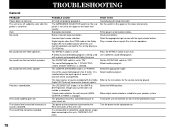
... LFE/BASS OUT mode is being used with material not encoded with Dolby Surround. Select the appropriate input source with the Dolby Digital (AC-3) do not have center channel signals. Make output mode selections suitable for your system does not include a subwoofer. Hum. The IMPEDANCE SELECTOR switch on . Press the EFFECT switch to the upper or the lower end exactly. TROUBLESHOOTING General PROBLEM Power does not come on the rear panel is selected. Bad cable connection. A Dolby Surround decoding program is in . Set...
... LFE/BASS OUT mode is being used with material not encoded with Dolby Surround. Select the appropriate input source with the Dolby Digital (AC-3) do not have center channel signals. Make output mode selections suitable for your system does not include a subwoofer. Hum. The IMPEDANCE SELECTOR switch on . Press the EFFECT switch to the upper or the lower end exactly. TROUBLESHOOTING General PROBLEM Power does not come on the rear panel is selected. Bad cable connection. A Dolby Surround decoding program is in . Set...


