Setup Guide
Page 1
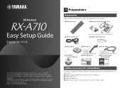
... this document. ■ Speaker cables (depending on the number of this guide and "Owner 's Manual" can be downloaded from the following website. A PDF format of speakers) ■ HDMI cable (x 2) ■ Audio pin cable (x 1) ■ Digital optical cable (x 1) (unnecessary if your TV supports ARC) http://download.yamaha.com/ ■ YPAO microphone Insert into the remote control in the correct polarity (+/-). ■ VIDEO AUX input cover ■ AM antenna ■ CD-ROM (Owner's Manual) ■ FM antenna ■ Power cable * The figure of...
... this document. ■ Speaker cables (depending on the number of this guide and "Owner 's Manual" can be downloaded from the following website. A PDF format of speakers) ■ HDMI cable (x 2) ■ Audio pin cable (x 1) ■ Digital optical cable (x 1) (unnecessary if your TV supports ARC) http://download.yamaha.com/ ■ YPAO microphone Insert into the remote control in the correct polarity (+/-). ■ VIDEO AUX input cover ■ AM antenna ■ CD-ROM (Owner's Manual) ■ FM antenna ■ Power cable * The figure of...
Setup Guide
Page 2
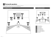
2 Placing the speakers Set up the speakers in the room by using the following diagram as a reference. For information on other speaker systems, refer to "Owner's Manual". 5.1-channel system 2 En 60° 60° 80° 80° 7.1-channel system 60° 60° 80° 80° 30 cm (1 ft) or more Front speaker (L) Front speaker (R) Center speaker Surround speaker (L) Surround speaker (R) Surround back speaker (L) Surround back speaker (R) Subwoofer
2 Placing the speakers Set up the speakers in the room by using the following diagram as a reference. For information on other speaker systems, refer to "Owner's Manual". 5.1-channel system 2 En 60° 60° 80° 80° 7.1-channel system 60° 60° 80° 80° 30 cm (1 ft) or more Front speaker (L) Front speaker (R) Center speaker Surround speaker (L) Surround speaker (R) Surround back speaker (L) Surround back speaker (R) Subwoofer
Setup Guide
Page 3
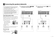
... unit (rear) R FRONT L CENTER SPEAKERS R SURROUND L R SURROUND BACK/ BI-AMP L R ZONE 2/PRESENCE L SINGLE EXTRA SP SUBWOOFER 2 Connect the center speaker ( CENTER terminal. ) to the FRONT ( / ) terminals. If the wires are colored to prevent confusion, connect the black wire to "6 Ω MIN". For details, see "Setting the speaker impedance" (p.16) in "Owner's Manual". • Use a subwoofer equipped with built-in amplifier. • Remove the power cable of this unit from the ends of the speaker + (red) c b FRONT cable, and...
... unit (rear) R FRONT L CENTER SPEAKERS R SURROUND L R SURROUND BACK/ BI-AMP L R ZONE 2/PRESENCE L SINGLE EXTRA SP SUBWOOFER 2 Connect the center speaker ( CENTER terminal. ) to the FRONT ( / ) terminals. If the wires are colored to prevent confusion, connect the black wire to "6 Ω MIN". For details, see "Setting the speaker impedance" (p.16) in "Owner's Manual". • Use a subwoofer equipped with built-in amplifier. • Remove the power cable of this unit from the ends of the speaker + (red) c b FRONT cable, and...
Setup Guide
Page 4
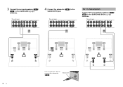
...CENTER SPEAKERS R SURROUND L R SURROUND BACK/ BI-AMP L R ZONE 2/PRESENCE L SINGLE EXTRA SP SUBWOOFER 4 Connect the subwoofer ( SUBWOOFER jack. ) to the This unit (rear) R FRONT L CENTER SPEAKERS R SURROUND L R SURROUND BACK/ BI-AMP L R ZONE 2/PRESENCE L SINGLE EXTRA SP SUBWOOFER For 7.1-channel system Connect the surround back speakers ( / ) to the SURROUND ( / ) terminals. This unit (rear) R FRONT L CENTER SPEAKERS R SURROUND L R SURROUND BACK/ BI-AMP L R ZONE 2/PRESENCE L SINGLE EXTRA SP SUBWOOFER 4 En Use an audio pin cable to connect the subwoofer...
...CENTER SPEAKERS R SURROUND L R SURROUND BACK/ BI-AMP L R ZONE 2/PRESENCE L SINGLE EXTRA SP SUBWOOFER 4 Connect the subwoofer ( SUBWOOFER jack. ) to the This unit (rear) R FRONT L CENTER SPEAKERS R SURROUND L R SURROUND BACK/ BI-AMP L R ZONE 2/PRESENCE L SINGLE EXTRA SP SUBWOOFER For 7.1-channel system Connect the surround back speakers ( / ) to the SURROUND ( / ) terminals. This unit (rear) R FRONT L CENTER SPEAKERS R SURROUND L R SURROUND BACK/ BI-AMP L R ZONE 2/PRESENCE L SINGLE EXTRA SP SUBWOOFER 4 En Use an audio pin cable to connect the subwoofer...

Setup Guide
Page 5
... VIDEO Y L HDMI OUT ARC HDMI 1 (BD/DVD) HDMI 2 HDMI 3 HDMI 4 ANTENNA AM FM 75Ω COMPONENT VIDEO PR PB VIDEO REMOTE IN OUT Y MONITOR OUT +12V 0.1A MAX. TRIGGER OUT R FRONT L CENTER R OPOTPTICICAAL L (TAVV1) AV 4 COAXIAL AV 2 COAXIAL (CD) AV 3 OPTICAL (TV) AV 4 AV 5 AV 6 AV OUT AUDIO 1 AUDIO 2 AUDIO OUT ZONE 2 OUT This unit (rear) HDMI 5 SPEAKERS R SURROUND L R SURROUND BACK/ BI-AMP L R ZONE 2/PRESENCE L SINGLE EXTRA SP AC IN SUBWOOFER Turn on this unit NATURAL SOUND AV RECEIVER RX-A710 MAIN ZONE INPUT ZONE 2 ZONE CONTROL INFO MEMORY PRESET...
... VIDEO Y L HDMI OUT ARC HDMI 1 (BD/DVD) HDMI 2 HDMI 3 HDMI 4 ANTENNA AM FM 75Ω COMPONENT VIDEO PR PB VIDEO REMOTE IN OUT Y MONITOR OUT +12V 0.1A MAX. TRIGGER OUT R FRONT L CENTER R OPOTPTICICAAL L (TAVV1) AV 4 COAXIAL AV 2 COAXIAL (CD) AV 3 OPTICAL (TV) AV 4 AV 5 AV 6 AV OUT AUDIO 1 AUDIO 2 AUDIO OUT ZONE 2 OUT This unit (rear) HDMI 5 SPEAKERS R SURROUND L R SURROUND BACK/ BI-AMP L R ZONE 2/PRESENCE L SINGLE EXTRA SP AC IN SUBWOOFER Turn on this unit NATURAL SOUND AV RECEIVER RX-A710 MAIN ZONE INPUT ZONE 2 ZONE CONTROL INFO MEMORY PRESET...
Setup Guide
Page 6
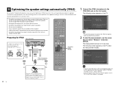
... (front) Turned on the front panel. The following screen appears on the TV when the measurement finishes. • If any obstacles are output at ear height in place. 1 Connect the YPAO microphone to the YPAO MIC jack on the subwoofer and set it from using a tripod to half. VOLUME CROSSOVER/ HIGH CUT MIN MAX MIN MAX YPAO microphone Listening position MAIN ZONE 2 CODE SET SOURCE RECEIVER HDMI 1 2 3 4 5 V-AUX AV 1 2 3 4 5 6 AUDIO DOCK TUNER SIRIUS...
... (front) Turned on the front panel. The following screen appears on the TV when the measurement finishes. • If any obstacles are output at ear height in place. 1 Connect the YPAO microphone to the YPAO MIC jack on the subwoofer and set it from using a tripod to half. VOLUME CROSSOVER/ HIGH CUT MIN MAX MIN MAX YPAO microphone Listening position MAIN ZONE 2 CODE SET SOURCE RECEIVER HDMI 1 2 3 4 5 V-AUX AV 1 2 3 4 5 6 AUDIO DOCK TUNER SIRIUS...
Setup Guide
Page 7
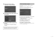
b Use the cursor keys to check the speaker connections. If the speaker is connected incorrectly: Turn off this unit. If "W-1: Out of Phase" appears Follow the procedure below to select "Wiring". Now optimization of an AV equipment, etc). Press RETURN and proceed to direct sunlight or high temperatures (top of the speaker settings is complete. • Since the YPAO microphone is sensitive to...
b Use the cursor keys to check the speaker connections. If the speaker is connected incorrectly: Turn off this unit. If "W-1: Out of Phase" appears Follow the procedure below to select "Wiring". Now optimization of an AV equipment, etc). Press RETURN and proceed to direct sunlight or high temperatures (top of the speaker settings is complete. • Since the YPAO microphone is sensitive to...
Setup Guide
Page 8
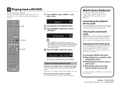
.../DVD player. 3 Press STRAIGHT repeatedly to select "STRAIGHT". It may be heard from the surround back speakers. 4 Press VOLUME to adjust the volume. Playing back from a specific speaker See "Troubleshooting" (p.109) in "Owner's Manual". This unit has various other functions. Volume -30.0dB SW L CR SL SR Now the basic setup procedure is enabled, each speaker produces each channel audio signal directly (without sound field processing). No sound is heard from iPod (p.54) By using a USB cable...
.../DVD player. 3 Press STRAIGHT repeatedly to select "STRAIGHT". It may be heard from the surround back speakers. 4 Press VOLUME to adjust the volume. Playing back from a specific speaker See "Troubleshooting" (p.109) in "Owner's Manual". This unit has various other functions. Volume -30.0dB SW L CR SL SR Now the basic setup procedure is enabled, each speaker produces each channel audio signal directly (without sound field processing). No sound is heard from iPod (p.54) By using a USB cable...


