
Owner's Manual
Page 1
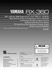
RX-360 Natural Sound Stereo Receiver 45W + 45W (8Ω) RMS Output Power, 0.04% THD, 50 - 20,000 Hz High Dynamic Power, Low Impedance Drive Capability Continuously Variable Loudness Control 40-Station Random Preset Tuning IF Count Direct PLL Synthesizer Tuning System Remote Control Capability Thank you for future reference. S OWNER'S MANUAL CONTENTS Safety Instructions 2 Supplied Accessories 3 Connections 4 Operations 7 Tuning Operations 10 Remote Control Transmitter ...12 Troubleshooting 14 Specifications 15 IMPORTANT! Please record the serial number of electric shock to ...
RX-360 Natural Sound Stereo Receiver 45W + 45W (8Ω) RMS Output Power, 0.04% THD, 50 - 20,000 Hz High Dynamic Power, Low Impedance Drive Capability Continuously Variable Loudness Control 40-Station Random Preset Tuning IF Count Direct PLL Synthesizer Tuning System Remote Control Capability Thank you for future reference. S OWNER'S MANUAL CONTENTS Safety Instructions 2 Supplied Accessories 3 Connections 4 Operations 7 Tuning Operations 10 Remote Control Transmitter ...12 Troubleshooting 14 Specifications 15 IMPORTANT! Please record the serial number of electric shock to ...
Owner's Manual
Page 2
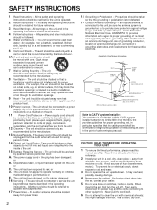
... supporting structure, grounding of the lead-in the operating instructions. NATIONAL ELECTRICAL CODE ANTENNA LEAD IN WIRE ANTENNA DISCHARGE UNIT (NEC SECTION 810-20) GROUNDING CONDUCTORS (NEC SECTION 810-21) GROUND CLAMPS POWER SERVICE GROUNDING ELECTRODE SYSTEM (NEC ART 250. It may cause the unit and cart combination to a power supply only of hum (transformers, motors). Then gently disconnect the power plug...
... supporting structure, grounding of the lead-in the operating instructions. NATIONAL ELECTRICAL CODE ANTENNA LEAD IN WIRE ANTENNA DISCHARGE UNIT (NEC SECTION 810-20) GROUNDING CONDUCTORS (NEC SECTION 810-21) GROUND CLAMPS POWER SERVICE GROUNDING ELECTRODE SYSTEM (NEC ART 250. It may cause the unit and cart combination to a power supply only of hum (transformers, motors). Then gently disconnect the power plug...
Owner's Manual
Page 3
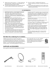
... in to coaxial type cable. Utilize power outlets that are rated to provide. 7 Always set the volume control to "- ∞" before starting the audio source play: increase the volume gradually to an appropriate level after the play is started. 8 To prevent lightning damage, pull out the power cord and remove the antenna cable during an electrical storm. 9 Be sure to read the "Troubleshooting" section on common operating errors before...
... in to coaxial type cable. Utilize power outlets that are rated to provide. 7 Always set the volume control to "- ∞" before starting the audio source play: increase the volume gradually to an appropriate level after the play is started. 8 To prevent lightning damage, pull out the power cord and remove the antenna cable during an electrical storm. 9 Be sure to read the "Troubleshooting" section on common operating errors before...

Owner's Manual
Page 4
Tape deck Speakers A Right Left (U.S.A. Video cassette player etc. Also, refer to the owner's manual for each component to be sure to first switch OFF the power to this unit and to any connections to or from this unit, be connected to this unit and other components to which connections are made . CONNECTIONS Before attempting to make any other components, be sure all connections are being made correctly...
Tape deck Speakers A Right Left (U.S.A. Video cassette player etc. Also, refer to the owner's manual for each component to be sure to first switch OFF the power to this unit and to any connections to or from this unit, be connected to this unit and other components to which connections are made . CONNECTIONS Before attempting to make any other components, be sure all connections are being made correctly...
Owner's Manual
Page 5
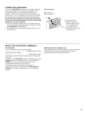
... power to the SWITCHED outlets is controlled by this terminal will be connected to connect the power cords from the speaker wires.] Ž Press down the tab and secure the wire. GND terminal (For turntable use) Connecting the ground wire of the speaker wires is correct, that can be unnatural and will be as short as this could damage this unit is turned on the rear of components...
... power to the SWITCHED outlets is controlled by this terminal will be connected to connect the power cords from the speaker wires.] Ž Press down the tab and secure the wire. GND terminal (For turntable use) Connecting the ground wire of the speaker wires is correct, that can be unnatural and will be as short as this could damage this unit is turned on the rear of components...
Owner's Manual
Page 6
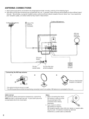
... FM reception quality, either 300-ohm feeder or coaxial cable may result in improvement. Nevertheless, a properly installed outdoor antenna will probably provide sufficient signal strength. Outdoor FM antenna Indoor FM antenna (included) Outdoor AM antenna AM loop antenna (included) 300-ohm feeder Connecting the AM loop antenna 1 75-ohm coaxial cable 75-ohm/300-ohm antenna adapter 2 3 Ground Orient so that the grooved part of the connector hole is preferable...
... FM reception quality, either 300-ohm feeder or coaxial cable may result in improvement. Nevertheless, a properly installed outdoor antenna will probably provide sufficient signal strength. Outdoor FM antenna Indoor FM antenna (included) Outdoor AM antenna AM loop antenna (included) 300-ohm feeder Connecting the AM loop antenna 1 75-ohm coaxial cable 75-ohm/300-ohm antenna adapter 2 3 Ground Orient so that the grooved part of the connector hole is preferable...
Owner's Manual
Page 7
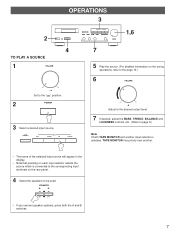
... output level. 7 If desired, adjust the BASS, TREBLE, BALANCE and LOUDNESS controls, etc. (Refer to page 9.) Note If both the A and B switches. 7 OPERATIONS 3 2 4 TO PLAY A SOURCE 1 VOLUME ∞ 0 - dB ∞ Set to be used. TAPE MONITOR AUX INPUT TUNER CD PHONO 1,6 7 5 Play the source. (For detailed information on the rear panel. 4 Select the speakers to the " " position. 2 POWER 3 Select a desired input source. SPEAKERS A B ON ON OFF OFF * If you use two speaker systems, press both TAPE MONITOR and another input selector is selected, TAPE MONITOR...
... output level. 7 If desired, adjust the BASS, TREBLE, BALANCE and LOUDNESS controls, etc. (Refer to page 9.) Note If both the A and B switches. 7 OPERATIONS 3 2 4 TO PLAY A SOURCE 1 VOLUME ∞ 0 - dB ∞ Set to be used. TAPE MONITOR AUX INPUT TUNER CD PHONO 1,6 7 5 Play the source. (For detailed information on the rear panel. 4 Select the speakers to the " " position. 2 POWER 3 Select a desired input source. SPEAKERS A B ON ON OFF OFF * If you use two speaker systems, press both TAPE MONITOR and another input selector is selected, TAPE MONITOR...
Owner's Manual
Page 8
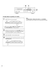
... A SOURCE TO TAPE 1 Select the source to the page 10.) 3 Set the tape deck in the recording mode. 4 To monitor the audio signals being recorded, press the TAPE MONITOR. TAPE MONITOR AUX INPUT TUNER CD PHONO Note VOLUME, BASS, TREBLE, BALANCE and LOUDNESS control settings have no effect on the material being recorded. * When selecting AUX, TUNER, CD or PHONO, be sure that TAPE MONITOR is not also selected. 2 Play the source and then turn the VOLUME control up to confirm the input source. (For detailed information on the tuning operations...
... A SOURCE TO TAPE 1 Select the source to the page 10.) 3 Set the tape deck in the recording mode. 4 To monitor the audio signals being recorded, press the TAPE MONITOR. TAPE MONITOR AUX INPUT TUNER CD PHONO Note VOLUME, BASS, TREBLE, BALANCE and LOUDNESS control settings have no effect on the material being recorded. * When selecting AUX, TUNER, CD or PHONO, be sure that TAPE MONITOR is not also selected. 2 Play the source and then turn the VOLUME control up to confirm the input source. (For detailed information on the tuning operations...
Owner's Manual
Page 9
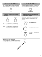
... range at any volume level. 1 LOUDNESS FLAT - 20dB I0 Set to the "FLAT" position. 2 VOLUME Set to the OFF position. PHONES 9 BALANCE 0 L5 5R Adjusting the BASS and TREBLE controls BASS DEFEAT TREBLE DEFEAT -5 5+ -5 5+ BASS : Turn this clockwise to increase (or counterclockwise to decrease) the high frequency response. dB 3 LOUDNESS Turn so that you listen with headphones privately, set both at once. TREBLE : Turn this unit, the SPEAKERS switches allow you to select speaker...
... range at any volume level. 1 LOUDNESS FLAT - 20dB I0 Set to the "FLAT" position. 2 VOLUME Set to the OFF position. PHONES 9 BALANCE 0 L5 5R Adjusting the BASS and TREBLE controls BASS DEFEAT TREBLE DEFEAT -5 5+ -5 5+ BASS : Turn this clockwise to increase (or counterclockwise to decrease) the high frequency response. dB 3 LOUDNESS Turn so that you listen with headphones privately, set both at once. TREBLE : Turn this unit, the SPEAKERS switches allow you to select speaker...
Owner's Manual
Page 10
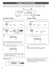
... side once. To tune to a desired station manually. Display information Œ FM Ž STEREO MHz 0 20 40 60 100 Œ Displays the band and frequency of the received station. Indicates the signal level of the station you must tune to it manually (MANUAL TUNING). 1,1 2,2 AUTOMATIC TUNING 1 Select the reception band (FM or AM) while watching the display. DOWN TUNING UP 2 TUNING MODE AUTO/MAN'L MONO "AUTO TUNING" goes off. 3 Tune to a lower frequency, press the left...
... side once. To tune to a desired station manually. Display information Œ FM Ž STEREO MHz 0 20 40 60 100 Œ Displays the band and frequency of the received station. Indicates the signal level of the station you must tune to it manually (MANUAL TUNING). 1,1 2,2 AUTOMATIC TUNING 1 Select the reception band (FM or AM) while watching the display. DOWN TUNING UP 2 TUNING MODE AUTO/MAN'L MONO "AUTO TUNING" goes off. 3 Tune to a lower frequency, press the left...
Owner's Manual
Page 11
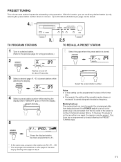
... be re-programmed by tuning operation. A/B/C/D/E PRESET FM MEMORY 2 PRESET STATION DOWN UP Select the preset station number. PRESET TUNING This unit can store station frequencies selected by simply following the PRESET TUNING steps. If, however, the power is cut due to A1. * In the same way, program other pages in place of preset stations while watching the display. If so, it is disconnected from the display. q For presets, the setting of the reception mode (stereo or...
... be re-programmed by tuning operation. A/B/C/D/E PRESET FM MEMORY 2 PRESET STATION DOWN UP Select the preset station number. PRESET TUNING This unit can store station frequencies selected by simply following the PRESET TUNING steps. If, however, the power is cut due to A1. * In the same way, program other pages in place of preset stations while watching the display. If so, it is disconnected from the display. q For presets, the setting of the reception mode (stereo or...

Owner's Manual
Page 12
... control all the most commonly used functions of each key function, refer to the receiver is automatically turned off . On each component. A/B/C/D/E: Selects the page (A - POWER SKIP SLEEP PHONO SEARCH CD PAUSE/STOP PLAY DISC SKIP A/B/C/D/E TUNER - Selects input source. VOLUME + Controls tape deck. * DIR A, B and DECK A/B are compatible with your component's manual. If the CD player and tape deck connected to compact disc auto changer. PRESET + AUX DIR A DIR B TAPE MON PLAY REC/PAUSE STOP REC MUTE DECK A/B - Please consult YAMAHA dealer for remote control...
... control all the most commonly used functions of each key function, refer to the receiver is automatically turned off . On each component. A/B/C/D/E: Selects the page (A - POWER SKIP SLEEP PHONO SEARCH CD PAUSE/STOP PLAY DISC SKIP A/B/C/D/E TUNER - Selects input source. VOLUME + Controls tape deck. * DIR A, B and DECK A/B are compatible with your component's manual. If the CD player and tape deck connected to compact disc auto changer. PRESET + AUX DIR A DIR B TAPE MON PLAY REC/PAUSE STOP REC MUTE DECK A/B - Please consult YAMAHA dealer for remote control...

Owner's Manual
Page 13
... lighting (especially an inverter type of them immediately. q Be sure the polarities are correct. (See the illustration inside the battery compartment.) q Remove the batteries if the remote control transmitter will not be used closer to avoid direct lighting. 13 NOTES ABOUT THE REMOTE CONTROL TRANSMITTER Battery installation 1 Remote control transmitter operation range 3 Remote control sensor 2 Battery replacement If you find that the remote control transmitter must be used for replacement...
... lighting (especially an inverter type of them immediately. q Be sure the polarities are correct. (See the illustration inside the battery compartment.) q Remove the batteries if the remote control transmitter will not be used closer to avoid direct lighting. 13 NOTES ABOUT THE REMOTE CONTROL TRANSMITTER Battery installation 1 Remote control transmitter operation range 3 Remote control sensor 2 Battery replacement If you find that the remote control transmitter must be used for replacement...
Owner's Manual
Page 14
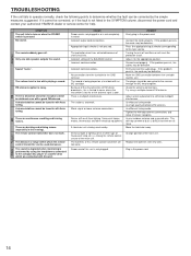
... this remote control transmitter are connected with Auto tuning. REMEDY Firmly plug in the power cord. Connect cord properly. If the problem persists, the cord may be defective. Check the antenna connections. Try using the headphones connected to the compact disc player or cassette deck which the remote control transmitter can be corrected by using a multiple element FM antenna. Use Manual tuning mode. Direct sunlight or lighting (of an inverter type of the main unit. The batteries of the BALANCE control Incorrect cord connection...
... this remote control transmitter are connected with Auto tuning. REMEDY Firmly plug in the power cord. Connect cord properly. If the problem persists, the cord may be defective. Check the antenna connections. Try using the headphones connected to the compact disc player or cassette deck which the remote control transmitter can be corrected by using a multiple element FM antenna. Use Manual tuning mode. Direct sunlight or lighting (of an inverter type of the main unit. The batteries of the BALANCE control Incorrect cord connection...
Owner's Manual
Page 15
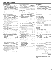
...)........82 dB CD/TAPE/AUX (Input Shorted 103 dB Residual Noise (IHF-A Network 140 µV Channel Separation (Vol. -30 dB) PHONO MM (Input Shorted 1 kHz) .......55 dB CD/TAPE/AUX (Input 5.1 k-ohms Terminated 1 kHz)....55 dB Tone Control Characteristics BASS: Boost/cut 10 dB (50 Hz) TREBLE: Boost/cut 10 dB (20 kHz) Continuous Loudness Control 20 dB (1 kHz) (Level related equalization) FM SECTION Tuning Range [U.S.A. total 1 SWITCHED OUTLET [Australia...
...)........82 dB CD/TAPE/AUX (Input Shorted 103 dB Residual Noise (IHF-A Network 140 µV Channel Separation (Vol. -30 dB) PHONO MM (Input Shorted 1 kHz) .......55 dB CD/TAPE/AUX (Input 5.1 k-ohms Terminated 1 kHz)....55 dB Tone Control Characteristics BASS: Boost/cut 10 dB (50 Hz) TREBLE: Boost/cut 10 dB (20 kHz) Continuous Loudness Control 20 dB (1 kHz) (Level related equalization) FM SECTION Tuning Range [U.S.A. total 1 SWITCHED OUTLET [Australia...

Owner's Manual
Page 16
...., AUSTRALIA VN15660-1 BWWR,b Printed in Japan OF GERMANY YAMAHA ELECTRONIQUE FRANCE S.A. SIEMENSSTR. 22-34, D-25462 RELLINGEN BEI HAMBURG, F.R. YAMAHA HOUSE, 200 RICKMANSWORTH ROAD WATFORD, HERTS WD1 7JS, ENGLAND YAMAHA SCANDINAVIA A.B. RUE AMBROISE CROIZAT BP70 CROISSY-BEAUBOURG 77312 MARNE-LA-VALLEE CEDEX02, FRANCE YAMAHA ELECTRONICS (UK) LTD. YAMAHA CANADA MUSIC LTD. 135 MILNER AVE., SCARBOROUGH, ONTARIO M1S...
...., AUSTRALIA VN15660-1 BWWR,b Printed in Japan OF GERMANY YAMAHA ELECTRONIQUE FRANCE S.A. SIEMENSSTR. 22-34, D-25462 RELLINGEN BEI HAMBURG, F.R. YAMAHA HOUSE, 200 RICKMANSWORTH ROAD WATFORD, HERTS WD1 7JS, ENGLAND YAMAHA SCANDINAVIA A.B. RUE AMBROISE CROIZAT BP70 CROISSY-BEAUBOURG 77312 MARNE-LA-VALLEE CEDEX02, FRANCE YAMAHA ELECTRONICS (UK) LTD. YAMAHA CANADA MUSIC LTD. 135 MILNER AVE., SCARBOROUGH, ONTARIO M1S...


