Owners Manual
Page 4
... turntable touches the surface of the unit to rain or moisture. • Do not use . Condensation might cause an electric shock since this Yamaha subwoofer system. are continuously output at least 20 cm of space above, behind and on switches, controls or connection wires. Use a clean, dry cloth... to obstruct heat radiation. This unit is dangerous and may distort images on the floor or other equipment. falls by this unit near the YST port of excessive vibration, dust, moisture and cold. In such a case, move this unit. Please read this unit. • When ...
... turntable touches the surface of the unit to rain or moisture. • Do not use . Condensation might cause an electric shock since this Yamaha subwoofer system. are continuously output at least 20 cm of space above, behind and on switches, controls or connection wires. Use a clean, dry cloth... to obstruct heat radiation. This unit is dangerous and may distort images on the floor or other equipment. falls by this unit near the YST port of excessive vibration, dust, moisture and cold. In such a case, move this unit. Please read this unit. • When ...
Owners Manual
Page 8
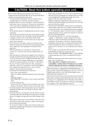
...to input line level signals from the amplifier. (Refer to "CONNECTIONS" for connecting to the OFF position. CONTROLS AND THEIR FUNCTIONS 1 Subwoofer rear panel OUTPUT TO SPEAKERS INPUT 1 FROM AMPLIFIER INPUT 2 AUTO STANDBY PHASE /MONO OFF HIGH LOW NORM REV POWER ON OFF (U.S.A....) 2 OUTPUT TO SPEAKERS R L R L FROM AMPLIFIER INPUT 1 3 INPUT AUTO PHASE 2 STANDBY L /MONO OFF LOWHIGH NORM REV R 45 6 Subwoofer front panel SUBWOOFER SYSTEM YST-RSW300 STANDBY/ON HIGH CUT VOLUME 78 40Hz 140Hz 9 0 10 0 1 POWER switch Normally, set to the HIGH or LOW position, the...
...to input line level signals from the amplifier. (Refer to "CONNECTIONS" for connecting to the OFF position. CONTROLS AND THEIR FUNCTIONS 1 Subwoofer rear panel OUTPUT TO SPEAKERS INPUT 1 FROM AMPLIFIER INPUT 2 AUTO STANDBY PHASE /MONO OFF HIGH LOW NORM REV POWER ON OFF (U.S.A....) 2 OUTPUT TO SPEAKERS R L R L FROM AMPLIFIER INPUT 1 3 INPUT AUTO PHASE 2 STANDBY L /MONO OFF LOWHIGH NORM REV R 45 6 Subwoofer front panel SUBWOOFER SYSTEM YST-RSW300 STANDBY/ON HIGH CUT VOLUME 78 40Hz 140Hz 9 0 10 0 1 POWER switch Normally, set to the HIGH or LOW position, the...
Owners Manual
Page 16
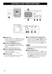
model) 7 SUBWOOFER SYSTEM YST-RSW300 STANDBY/ON HIGH CUT VOLUME 40Hz 140Hz 0 10 3 5,6 1,6 Subwoofer front panel 1 Set the VOLUME control to minimum (0). 2 Turn on the power of your whole sound system by following the procedures described below. ...must make this adjustment again. • For adjusting the VOLUME control, the HIGH CUT control and the PHASE switch, refer to "FREQUENCY CHARACTERISTICS" on the subwoofer. * The status indicator lights up in green. 4 Play a source containing low-frequency signals and adjust the amplifier's volume control to the desired listening level....
model) 7 SUBWOOFER SYSTEM YST-RSW300 STANDBY/ON HIGH CUT VOLUME 40Hz 140Hz 0 10 3 5,6 1,6 Subwoofer front panel 1 Set the VOLUME control to minimum (0). 2 Turn on the power of your whole sound system by following the procedures described below. ...must make this adjustment again. • For adjusting the VOLUME control, the HIGH CUT control and the PHASE switch, refer to "FREQUENCY CHARACTERISTICS" on the subwoofer. * The status indicator lights up in green. 4 Play a source containing low-frequency signals and adjust the amplifier's volume control to the desired listening level....
Owners Manual
Page 18
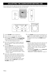
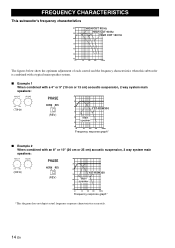
... 70 60 50 40 20 50 100 200 500Hz The figures below show the optimum adjustment of each control and the frequency characteristics when this subwoofer is combined with a typical main speaker system. ■ Example 1 When combined with a 4" or 5" (10 cm or 13 cm) acoustic suspension, ...cm) acoustic suspension, 2 way system main speakers: HIGH CUT VOLUME 40Hz 140Hz 0 10 (50Hz) PHASE NORM REV (REV) dB 90 80 YST-RSW300 70 60 Main speaker 50 40 20 50 100 200 500Hz Frequency response graph* *This diagram does not depict actual frequency response characteristics accurately. ...
... 70 60 50 40 20 50 100 200 500Hz The figures below show the optimum adjustment of each control and the frequency characteristics when this subwoofer is combined with a typical main speaker system. ■ Example 1 When combined with a 4" or 5" (10 cm or 13 cm) acoustic suspension, ...cm) acoustic suspension, 2 way system main speakers: HIGH CUT VOLUME 40Hz 140Hz 0 10 (50Hz) PHASE NORM REV (REV) dB 90 80 YST-RSW300 70 60 Main speaker 50 40 20 50 100 200 500Hz Frequency response graph* *This diagram does not depict actual frequency response characteristics accurately. ...

