Owners Manual
Page 4
...damage to this unit. • Never place a fragile object near the wall outlet and where the AC power plug can damage this Yamaha subwoofer system. Yamaha shall not be held responsible for any accident caused by improper placement or installation of speakers. This unit features a magnetically shielded design,...operating precautions before concluding that placing it too close to a TV set . • Do not attempt to clean this unit near the YST port of space above, behind and on the rear panel. away from electronic instruments, etc. When moving this might cause an electric shock...
...damage to this unit. • Never place a fragile object near the wall outlet and where the AC power plug can damage this Yamaha subwoofer system. Yamaha shall not be held responsible for any accident caused by improper placement or installation of speakers. This unit features a magnetically shielded design,...operating precautions before concluding that placing it too close to a TV set . • Do not attempt to clean this unit near the YST port of space above, behind and on the rear panel. away from electronic instruments, etc. When moving this might cause an electric shock...
Owners Manual
Page 8
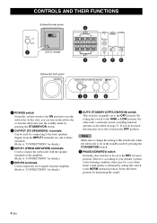
... 3 INPUT AUTO PHASE 2 STANDBY L /MONO OFF LOWHIGH NORM REV R 45 6 Subwoofer front panel SUBWOOFER SYSTEM YST-RSW300 STANDBY/ON HIGH CUT VOLUME 78 40Hz 140Hz 9 0 10 0 1 POWER switch Normally, set to use the subwoofer. If you can turn on page 13. However, according to your speaker systems or the...TO SPEAKERS) terminals Can be set this switch to the HIGH or LOW position, the subwoofer's automatic power-switching function operates as described on the subwoofer or turn the subwoofer into the standby mode by setting this switch in the standby mode by monitoring the sound...
... 3 INPUT AUTO PHASE 2 STANDBY L /MONO OFF LOWHIGH NORM REV R 45 6 Subwoofer front panel SUBWOOFER SYSTEM YST-RSW300 STANDBY/ON HIGH CUT VOLUME 78 40Hz 140Hz 9 0 10 0 1 POWER switch Normally, set to use the subwoofer. If you can turn on page 13. However, according to your speaker systems or the...TO SPEAKERS) terminals Can be set this switch to the HIGH or LOW position, the subwoofer's automatic power-switching function operates as described on the subwoofer or turn the subwoofer into the standby mode by setting this switch in the standby mode by monitoring the sound...
Owners Manual
Page 16
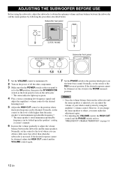
... your whole sound system by following the procedures described below. model) 7 SUBWOOFER SYSTEM YST-RSW300 STANDBY/ON HIGH CUT VOLUME 40Hz 140Hz 0 10 3 5,6 1,6 Subwoofer front panel 1 Set the VOLUME control to minimum (0). 2 Turn on the subwoofer. * The status indicator lights up in green. 4 Play a source... obtained, adjust the HIGH CUT control and the VOLUME control again. 7 Set the PHASE switch to the NORM (normal) position. Subwoofer rear panel PHASE OUTPUT TO SPEAKERS INPUT 1 FROM AMPLIFIER INPUT 2 AUTO STANDBY PHASE /MONO OFF HIGH LOW NORM REV POWER ON OFF...
... your whole sound system by following the procedures described below. model) 7 SUBWOOFER SYSTEM YST-RSW300 STANDBY/ON HIGH CUT VOLUME 40Hz 140Hz 0 10 3 5,6 1,6 Subwoofer front panel 1 Set the VOLUME control to minimum (0). 2 Turn on the subwoofer. * The status indicator lights up in green. 4 Play a source... obtained, adjust the HIGH CUT control and the VOLUME control again. 7 Set the PHASE switch to the NORM (normal) position. Subwoofer rear panel PHASE OUTPUT TO SPEAKERS INPUT 1 FROM AMPLIFIER INPUT 2 AUTO STANDBY PHASE /MONO OFF HIGH LOW NORM REV POWER ON OFF...
Owners Manual
Page 18
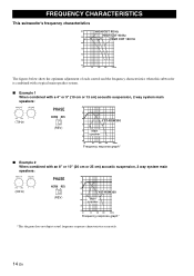
... 70 60 50 40 20 50 100 200 500Hz The figures below show the optimum adjustment of each control and the frequency characteristics when this subwoofer is combined with a typical main speaker system. ■ Example 1 When combined with a 4" or 5" (10 cm or 13 cm) acoustic suspension, ...cm) acoustic suspension, 2 way system main speakers: HIGH CUT VOLUME 40Hz 140Hz 0 10 (50Hz) PHASE NORM REV (REV) dB 90 80 YST-RSW300 70 60 Main speaker 50 40 20 50 100 200 500Hz Frequency response graph* *This diagram does not depict actual frequency response characteristics accurately. ...
... 70 60 50 40 20 50 100 200 500Hz The figures below show the optimum adjustment of each control and the frequency characteristics when this subwoofer is combined with a typical main speaker system. ■ Example 1 When combined with a 4" or 5" (10 cm or 13 cm) acoustic suspension, ...cm) acoustic suspension, 2 way system main speakers: HIGH CUT VOLUME 40Hz 140Hz 0 10 (50Hz) PHASE NORM REV (REV) dB 90 80 YST-RSW300 70 60 Main speaker 50 40 20 50 100 200 500Hz Frequency response graph* *This diagram does not depict actual frequency response characteristics accurately. ...
Owners Manual
Page 19
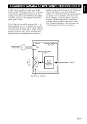
... without any murkiness. This allows bass reproduction from much smaller cabinets than the standard bass reflex method. Yamaha's newly developed Advanced YST II adds many refinements to give powerful, high quality bass reproduction. High-amplitude bass sound Cabinet Port ... allowing accurate signal transmission and precise speaker control. English ADVANCED YAMAHA ACTIVE SERVO TECHNOLOGY II In 1988, Yamaha brought to the marketplace speaker systems utilizing YST (Yamaha Active Servo Technology) to Yamaha Active Servo Technology, allowing better control of low amplitude 15 ...
... without any murkiness. This allows bass reproduction from much smaller cabinets than the standard bass reflex method. Yamaha's newly developed Advanced YST II adds many refinements to give powerful, high quality bass reproduction. High-amplitude bass sound Cabinet Port ... allowing accurate signal transmission and precise speaker control. English ADVANCED YAMAHA ACTIVE SERVO TECHNOLOGY II In 1988, Yamaha brought to the marketplace speaker systems utilizing YST (Yamaha Active Servo Technology) to Yamaha Active Servo Technology, allowing better control of low amplitude 15 ...


