Owners Manual
Page 4
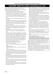
...panel of this unit with a higher voltage than specified is faulty. • Install this unit near the YST port of speakers. CAUTION: Read this before use this unit for future reference. • Install this manual ...disconnect the power plug and the wires connected to obstruct heat radiation. If something drops into the YST port located on both sides of humming (transformers, motors). If the object falls or drops ... a newspaper, a tablecloth, a curtain, etc. In this state, this Yamaha subwoofer system. Thank you for selecting this unit is the owner's responsibility.
...panel of this unit with a higher voltage than specified is faulty. • Install this unit near the YST port of speakers. CAUTION: Read this before use this unit for future reference. • Install this manual ...disconnect the power plug and the wires connected to obstruct heat radiation. If something drops into the YST port located on both sides of humming (transformers, motors). If the object falls or drops ... a newspaper, a tablecloth, a curtain, etc. In this state, this Yamaha subwoofer system. Thank you for selecting this unit is the owner's responsibility.
Owners Manual
Page 8
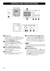
... SPEAKERS) terminals Can be used for details.) 5 AUTO STANDBY (OFF/LOW/HIGH) switch This switch is originally set to use the subwoofer. By setting this switch to the ON position to the REV (reverse) position. However, according to your speaker systems or the listening...2 OUTPUT TO SPEAKERS R L R L FROM AMPLIFIER INPUT 1 3 INPUT AUTO PHASE 2 STANDBY L /MONO OFF LOWHIGH NORM REV R 45 6 Subwoofer front panel SUBWOOFER SYSTEM YST-RSW300 STANDBY/ON HIGH CUT VOLUME 78 40Hz 140Hz 9 0 10 0 1 POWER switch Normally, set in the OFF position. If you do not need this...
... SPEAKERS) terminals Can be used for details.) 5 AUTO STANDBY (OFF/LOW/HIGH) switch This switch is originally set to use the subwoofer. By setting this switch to the ON position to the REV (reverse) position. However, according to your speaker systems or the listening...2 OUTPUT TO SPEAKERS R L R L FROM AMPLIFIER INPUT 1 3 INPUT AUTO PHASE 2 STANDBY L /MONO OFF LOWHIGH NORM REV R 45 6 Subwoofer front panel SUBWOOFER SYSTEM YST-RSW300 STANDBY/ON HIGH CUT VOLUME 78 40Hz 140Hz 9 0 10 0 1 POWER switch Normally, set in the OFF position. If you do not need this...
Owners Manual
Page 16
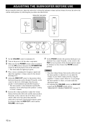
...7 SUBWOOFER SYSTEM YST-RSW300 STANDBY/ON HIGH CUT VOLUME 40Hz 140Hz 0 10 3 5,6 1,6 Subwoofer front panel 1 Set the VOLUME control to minimum (0). 2 Turn on the power of your whole sound system by following the procedures described below. Notes • Once the volume balance between the subwoofer and.... • For adjusting the VOLUME control, the HIGH CUT control and the PHASE switch, refer to "FREQUENCY CHARACTERISTICS" on the subwoofer. * The status indicator lights up in green. 4 Play a source containing low-frequency signals and adjust the amplifier's volume control to...
...7 SUBWOOFER SYSTEM YST-RSW300 STANDBY/ON HIGH CUT VOLUME 40Hz 140Hz 0 10 3 5,6 1,6 Subwoofer front panel 1 Set the VOLUME control to minimum (0). 2 Turn on the power of your whole sound system by following the procedures described below. Notes • Once the volume balance between the subwoofer and.... • For adjusting the VOLUME control, the HIGH CUT control and the PHASE switch, refer to "FREQUENCY CHARACTERISTICS" on the subwoofer. * The status indicator lights up in green. 4 Play a source containing low-frequency signals and adjust the amplifier's volume control to...
Owners Manual
Page 18
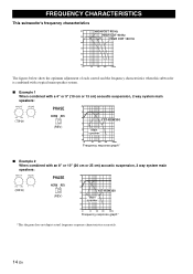
... 70 60 50 40 20 50 100 200 500Hz The figures below show the optimum adjustment of each control and the frequency characteristics when this subwoofer is combined with a typical main speaker system. ■ Example 1 When combined with a 4" or 5" (10 cm or 13 cm) acoustic suspension, ...cm) acoustic suspension, 2 way system main speakers: HIGH CUT VOLUME 40Hz 140Hz 0 10 (50Hz) PHASE NORM REV (REV) dB 90 80 YST-RSW300 70 60 Main speaker 50 40 20 50 100 200 500Hz Frequency response graph* *This diagram does not depict actual frequency response characteristics accurately. ...
... 70 60 50 40 20 50 100 200 500Hz The figures below show the optimum adjustment of each control and the frequency characteristics when this subwoofer is combined with a typical main speaker system. ■ Example 1 When combined with a 4" or 5" (10 cm or 13 cm) acoustic suspension, ...cm) acoustic suspension, 2 way system main speakers: HIGH CUT VOLUME 40Hz 140Hz 0 10 (50Hz) PHASE NORM REV (REV) dB 90 80 YST-RSW300 70 60 Main speaker 50 40 20 50 100 200 500Hz Frequency response graph* *This diagram does not depict actual frequency response characteristics accurately. ...
Owners Manual
Page 19
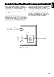
... SERVO TECHNOLOGY II In 1988, Yamaha brought to the marketplace speaker systems utilizing YST (Yamaha Active Servo Technology) to Yamaha Active Servo Technology, allowing better control of the amplifier and resonance generated between the amplifier and speaker, ...direct connection between the speaker cabinet volume and port, it creates more stable performance and clear bass reproduction without any murkiness. Yamaha's newly developed Advanced YST II adds many refinements to give powerful, high quality bass reproduction. High-amplitude bass sound Cabinet Port Air woofer (Helmholtz...
... SERVO TECHNOLOGY II In 1988, Yamaha brought to the marketplace speaker systems utilizing YST (Yamaha Active Servo Technology) to Yamaha Active Servo Technology, allowing better control of the amplifier and resonance generated between the amplifier and speaker, ...direct connection between the speaker cabinet volume and port, it creates more stable performance and clear bass reproduction without any murkiness. Yamaha's newly developed Advanced YST II adds many refinements to give powerful, high quality bass reproduction. High-amplitude bass sound Cabinet Port Air woofer (Helmholtz...


