Owners Manual
Page 4
...you for selecting this unit, reduce the volume level. Place the unit apart from this Yamaha subwoofer system. Glass, china, small metallic etc. A burning candle etc. are continuously output ... or a foreign object into the set might damage the finish. If something drops into the YST port located on both sides of this unit: - It might also cause personal injury and/... sounds are continuously output, or when the stylus of a turntable touches the surface of this speaker system. • Vibration generated by super-bass frequencies may cause damage to other surfaces. &#...
...you for selecting this unit, reduce the volume level. Place the unit apart from this Yamaha subwoofer system. Glass, china, small metallic etc. A burning candle etc. are continuously output ... or a foreign object into the set might damage the finish. If something drops into the YST port located on both sides of this unit: - It might also cause personal injury and/... sounds are continuously output, or when the stylus of a turntable touches the surface of this speaker system. • Vibration generated by super-bass frequencies may cause damage to other surfaces. &#...
Owners Manual
Page 5
... CONTROLS AND THEIR FUNCTIONS ...4 CONNECTIONS ...6 [1] Connecting to line output (pin jack) terminals of the amplifier 6 [2] Connecting to speaker output terminals of the subwoofer 10 Plug in the home are 110/120/220/230-240 V AC, 50/60 Hz. Making sure that neither core is marked... of the amplifier 8 Connecting to the AC outlet ...11 ADJUSTING THE SUBWOOFER BEFORE USE ...12 AUTOMATIC POWER-SWITCHING FUNCTION 13 Changing the AUTO STANDBY setting ...13 FREQUENCY CHARACTERISTICS ...14 ADVANCED YAMAHA ACTIVE SERVO TECHNOLOGY II 15 TROUBLESHOOTING ...16 SPECIFICATIONS ...17 1 En This...
... CONTROLS AND THEIR FUNCTIONS ...4 CONNECTIONS ...6 [1] Connecting to line output (pin jack) terminals of the amplifier 6 [2] Connecting to speaker output terminals of the subwoofer 10 Plug in the home are 110/120/220/230-240 V AC, 50/60 Hz. Making sure that neither core is marked... of the amplifier 8 Connecting to the AC outlet ...11 ADJUSTING THE SUBWOOFER BEFORE USE ...12 AUTOMATIC POWER-SWITCHING FUNCTION 13 Changing the AUTO STANDBY setting ...13 FREQUENCY CHARACTERISTICS ...14 ADVANCED YAMAHA ACTIVE SERVO TECHNOLOGY II 15 TROUBLESHOOTING ...16 SPECIFICATIONS ...17 1 En This...
Owners Manual
Page 6
... control and the PHASE switch. • The Automatic power-switching function saves you the trouble of your main speakers. FEATURES SUPPLIED ACCESSORIES • This subwoofer system employs Advanced Yamaha Active Servo Technology II, which Yamaha has developed for reproducing higher quality super-bass sound (refer to page 15 for various listening conditions by connecting...
... control and the PHASE switch. • The Automatic power-switching function saves you the trouble of your main speakers. FEATURES SUPPLIED ACCESSORIES • This subwoofer system employs Advanced Yamaha Active Servo Technology II, which Yamaha has developed for reproducing higher quality super-bass sound (refer to page 15 for various listening conditions by connecting...
Owners Manual
Page 7
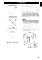
... the sound reflected by placing bookshelves etc. B Note There may cancel out each main speaker (see A). This is because "standing waves" have a good effect on the outside of two subwoofers is recommended to break up the parallel surfaces by the wall may be necessary to place... system, however, the use of either the right or the left main speaker (see B). It also may die because the sound from C moving by vibrations etc. ( : subwoofer : main speaker) 3 En In such a case, face the subwoofer obliquely to place it is placed directly facing the wall, the bass effect...
... the sound reflected by placing bookshelves etc. B Note There may cancel out each main speaker (see A). This is because "standing waves" have a good effect on the outside of two subwoofers is recommended to break up the parallel surfaces by the wall may be necessary to place... system, however, the use of either the right or the left main speaker (see B). It also may die because the sound from C moving by vibrations etc. ( : subwoofer : main speaker) 3 En In such a case, face the subwoofer obliquely to place it is placed directly facing the wall, the bass effect...
Owners Manual
Page 8
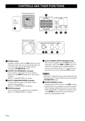
... level signals from the amplifier. (Refer to "CONNECTIONS" for connecting to the REV (reverse) position. model) 2 OUTPUT TO SPEAKERS R L R L FROM AMPLIFIER INPUT 1 3 INPUT AUTO PHASE 2 STANDBY L /MONO OFF LOWHIGH NORM REV R 45 6 Subwoofer front panel SUBWOOFER SYSTEM YST-RSW300 STANDBY/ON HIGH CUT VOLUME 78 40Hz 140Hz 9 0 10 0 1 POWER switch Normally, set to use the...
... level signals from the amplifier. (Refer to "CONNECTIONS" for connecting to the REV (reverse) position. model) 2 OUTPUT TO SPEAKERS R L R L FROM AMPLIFIER INPUT 1 3 INPUT AUTO PHASE 2 STANDBY L /MONO OFF LOWHIGH NORM REV R 45 6 Subwoofer front panel SUBWOOFER SYSTEM YST-RSW300 STANDBY/ON HIGH CUT VOLUME 78 40Hz 140Hz 9 0 10 0 1 POWER switch Normally, set to use the...
Owners Manual
Page 10
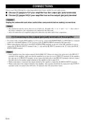
...8226; To connect with a Yamaha DSP amplifier (or AV receiver), connect the SUBWOOFER (or LOW PASS etc.) terminal on the rear of the DSP amplifier (or AV receiver) to the L /MONO INPUT2 terminal of the subwoofer. • When connecting the subwoofer to the SPLIT SUBWOOFER terminals on the rear panel ... will not produce sound. 6 En Also, refer to the owner's manual of your amplifier has no line output (pin jack) terminal Caution Unplug the subwoofer and other speakers should not be correct, that is to say L (left) to L, R (right) to R, "+" to "+" and "-" to "-". Notes • Some ...
...8226; To connect with a Yamaha DSP amplifier (or AV receiver), connect the SUBWOOFER (or LOW PASS etc.) terminal on the rear of the DSP amplifier (or AV receiver) to the L /MONO INPUT2 terminal of the subwoofer. • When connecting the subwoofer to the SPLIT SUBWOOFER terminals on the rear panel ... will not produce sound. 6 En Also, refer to the owner's manual of your amplifier has no line output (pin jack) terminal Caution Unplug the subwoofer and other speakers should not be correct, that is to say L (left) to L, R (right) to R, "+" to "+" and "-" to "-". Notes • Some ...

Owners Manual
Page 11
... cable (not included) Audio pin cable (not included) ■ Using two subwoofers OUTPUT TO SPEAKERS R L INPUT 2 L /MONO R L FROM AMPLIFIER R INPUT 1 Subwoofer OUTPUT TO SPEAKERS INPUT 1 FROM AMPLIFIER INPUT 2 AUTO STANDBY PHASE /MONO OFF HIGH LOW NORM REV POWER ON OFF Subwoofer OUTPUT TO SPEAKERS INPUT 1 FROM AMPLIFIER INPUT 2 AUTO STANDBY PHASE /MONO OFF HIGH LOW NORM...
... cable (not included) Audio pin cable (not included) ■ Using two subwoofers OUTPUT TO SPEAKERS R L INPUT 2 L /MONO R L FROM AMPLIFIER R INPUT 1 Subwoofer OUTPUT TO SPEAKERS INPUT 1 FROM AMPLIFIER INPUT 2 AUTO STANDBY PHASE /MONO OFF HIGH LOW NORM REV POWER ON OFF Subwoofer OUTPUT TO SPEAKERS INPUT 1 FROM AMPLIFIER INPUT 2 AUTO STANDBY PHASE /MONO OFF HIGH LOW NORM...
Owners Manual
Page 12
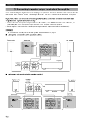
... INPUT 2 AUTO STANDBY PHASE /MONO OFF HIGH LOW NORM REV POWER ON OFF OUTPUT TO SPEAKERS R L INPUT 2 L /MONO R L FROM AMPLIFIER R INPUT 1 Left speaker Speaker output terminals Amplifier ■ Using two subwoofers (with speaker cables) Right speaker Speaker output terminals Left speaker Subwoofer OUTPUT TO SPEAKERS INPUT 1 FROM AMPLIFIER INPUT 2 AUTO STANDBY PHASE /MONO OFF HIGH LOW NORM REV POWER ON...
... INPUT 2 AUTO STANDBY PHASE /MONO OFF HIGH LOW NORM REV POWER ON OFF OUTPUT TO SPEAKERS R L INPUT 2 L /MONO R L FROM AMPLIFIER R INPUT 1 Left speaker Speaker output terminals Amplifier ■ Using two subwoofers (with speaker cables) Right speaker Speaker output terminals Left speaker Subwoofer OUTPUT TO SPEAKERS INPUT 1 FROM AMPLIFIER INPUT 2 AUTO STANDBY PHASE /MONO OFF HIGH LOW NORM REV POWER ON...
Owners Manual
Page 13
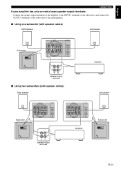
... of the subwoofer to the main speakers. ■ Using one subwoofer (with speaker cables) Right speaker Left speaker Subwoofer OUTPUT TO SPEAKERS INPUT 1 FROM AMPLIFIER INPUT 2 AUTO STANDBY PHASE /MONO OFF HIGH LOW NORM REV POWER ON OFF OUTPUT TO SPEAKERS R L INPUT 2 L /MONO R L FROM AMPLIFIER R INPUT 1 Amplifier Speaker output terminals ■ Using two subwoofers (with speaker cables) Right speaker Left speaker Subwoofer OUTPUT TO SPEAKERS INPUT...
... of the subwoofer to the main speakers. ■ Using one subwoofer (with speaker cables) Right speaker Left speaker Subwoofer OUTPUT TO SPEAKERS INPUT 1 FROM AMPLIFIER INPUT 2 AUTO STANDBY PHASE /MONO OFF HIGH LOW NORM REV POWER ON OFF OUTPUT TO SPEAKERS R L INPUT 2 L /MONO R L FROM AMPLIFIER R INPUT 1 Amplifier Speaker output terminals ■ Using two subwoofers (with speaker cables) Right speaker Left speaker Subwoofer OUTPUT TO SPEAKERS INPUT...
Owners Manual
Page 14
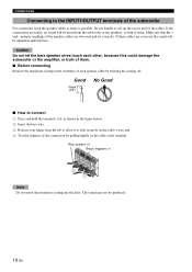
... the hole. The sound may not be unnatural and lack bass. Make sure that the + and - CONNECTIONS Connecting to the INPUT1/OUTPUT terminals of the subwoofer For connection, keep the speaker cables as short as shown in the figure below. 2 Insert the bare wire. 3 Release your finger from the... by pulling lightly on the cable at the extremity of each other, because this could damage the subwoofer or the amplifier, or both of the speaker cables are faulty, no sound will be produced. 10 En If these cables are reversed, the sound will be heard from the tab to allow ...
... the hole. The sound may not be unnatural and lack bass. Make sure that the + and - CONNECTIONS Connecting to the INPUT1/OUTPUT terminals of the subwoofer For connection, keep the speaker cables as short as shown in the figure below. 2 Insert the bare wire. 3 Release your finger from the... by pulling lightly on the cable at the extremity of each other, because this could damage the subwoofer or the amplifier, or both of the speaker cables are faulty, no sound will be produced. 10 En If these cables are reversed, the sound will be heard from the tab to allow ...
Owners Manual
Page 15
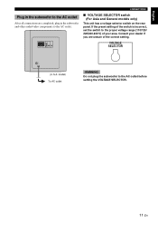
... OFF (U.S.A. OUTPUT TO SPEAKERS INPUT 1 FROM AMPLIFIER INPUT 2 AUTO STANDBY PHASE /MONO OFF HIGH LOW NORM REV CONNECTIONS ■ VOLTAGE SELECTOR switch (For Asia and General models only) This unit has a voltage selector switch on the rear panel. model) To AC outlet WARNING Do not plug the subwoofer to the proper voltage... range (110/120/ 220/230-240 V) of your dealer if you are completed, plug in the subwoofer to the AC outlet After all connections are unsure of the switch is incorrect, set the switch to the AC outlet before setting the VOLTAGE ...
... OFF (U.S.A. OUTPUT TO SPEAKERS INPUT 1 FROM AMPLIFIER INPUT 2 AUTO STANDBY PHASE /MONO OFF HIGH LOW NORM REV CONNECTIONS ■ VOLTAGE SELECTOR switch (For Asia and General models only) This unit has a voltage selector switch on the rear panel. model) To AC outlet WARNING Do not plug the subwoofer to the proper voltage... range (110/120/ 220/230-240 V) of your dealer if you are completed, plug in the subwoofer to the AC outlet After all connections are unsure of the switch is incorrect, set the switch to the AC outlet before setting the VOLTAGE ...
Owners Manual
Page 16
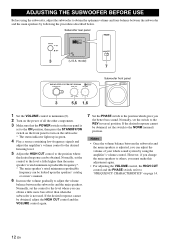
... control to the level a little higher than when the subwoofer is adjusted, you the better bass sound. model) 7 SUBWOOFER SYSTEM YST-RSW300 STANDBY/ON HIGH CUT VOLUME 40Hz 140Hz 0 10 3 5,6 1,6 Subwoofer front panel 1 Set the VOLUME control to the REV ...(reverse) position. Normally, set the switch to obtain the optimum volume and tone balance between the subwoofer and the main speakers is not used. ADJUSTING THE SUBWOOFER...
... control to the level a little higher than when the subwoofer is adjusted, you the better bass sound. model) 7 SUBWOOFER SYSTEM YST-RSW300 STANDBY/ON HIGH CUT VOLUME 40Hz 140Hz 0 10 3 5,6 1,6 Subwoofer front panel 1 Set the VOLUME control to the REV ...(reverse) position. Normally, set the switch to obtain the optimum volume and tone balance between the subwoofer and the main speakers is not used. ADJUSTING THE SUBWOOFER...
Owners Manual
Page 18
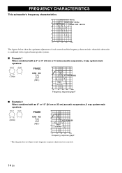
...characteristics when this subwoofer is combined with a typical main speaker system. ■ Example 1 When combined with a 4" or 5" (10 cm or 13 cm) acoustic suspension, 2 way system main speakers: HIGH CUT VOLUME 40Hz 140Hz 0 10 (70Hz) PHASE NORM REV (REV) dB 90 80 YST-RSW300 70 60 Main speaker 50 40 ...an 8" or 10" (20 cm or 25 cm) acoustic suspension, 2 way system main speakers: HIGH CUT VOLUME 40Hz 140Hz 0 10 (50Hz) PHASE NORM REV (REV) dB 90 80 YST-RSW300 70 60 Main speaker 50 40 20 50 100 200 500Hz Frequency response graph* *This diagram does not depict ...
...characteristics when this subwoofer is combined with a typical main speaker system. ■ Example 1 When combined with a 4" or 5" (10 cm or 13 cm) acoustic suspension, 2 way system main speakers: HIGH CUT VOLUME 40Hz 140Hz 0 10 (70Hz) PHASE NORM REV (REV) dB 90 80 YST-RSW300 70 60 Main speaker 50 40 ...an 8" or 10" (20 cm or 25 cm) acoustic suspension, 2 way system main speakers: HIGH CUT VOLUME 40Hz 140Hz 0 10 (50Hz) PHASE NORM REV (REV) dB 90 80 YST-RSW300 70 60 Main speaker 50 40 20 50 100 200 500Hz Frequency response graph* *This diagram does not depict ...
Owners Manual
Page 19
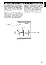
...) Advanced impedance Converter Active Servo Processing Amplifier Signals Signals of the forces driving the amplifier and speaker. English ADVANCED YAMAHA ACTIVE SERVO TECHNOLOGY II In 1988, Yamaha brought to the marketplace speaker systems utilizing YST (Yamaha Active Servo Technology) to Yamaha Active Servo Technology, allowing better control of low amplitude 15 En From the amplifier's point of...
...) Advanced impedance Converter Active Servo Processing Amplifier Signals Signals of the forces driving the amplifier and speaker. English ADVANCED YAMAHA ACTIVE SERVO TECHNOLOGY II In 1988, Yamaha brought to the marketplace speaker systems utilizing YST (Yamaha Active Servo Technology) to Yamaha Active Servo Technology, allowing better control of low amplitude 15 En From the amplifier's point of...
Owners Manual
Page 20
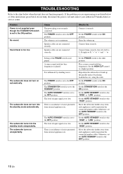
... contact your authorized Yamaha dealer or service center. If the problem you are experiencing is not proper. No sound. The subwoofer does not turn on unexpectedly. The subwoofer turns into the standby mode automatically. The POWER switch is set to the OFF position. Speaker cables are not ...AUTO STANDBY switch to the ON position. Set the AUTO STANDBY switch to the OFF position. Move the subwoofer farther away from such appliances and/or reposition the connected speaker cables. Otherwise, set the AUTO STANDBY switch to the "HIGH" position. Set the AUTO STANDBY switch...
... contact your authorized Yamaha dealer or service center. If the problem you are experiencing is not proper. No sound. The subwoofer does not turn on unexpectedly. The subwoofer turns into the standby mode automatically. The POWER switch is set to the OFF position. Speaker cables are not ...AUTO STANDBY switch to the ON position. Set the AUTO STANDBY switch to the OFF position. Move the subwoofer farther away from such appliances and/or reposition the connected speaker cables. Otherwise, set the AUTO STANDBY switch to the "HIGH" position. Set the AUTO STANDBY switch...
Owners Manual
Page 21
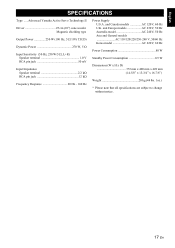
... Weight 20 kg (44 lbs. 1oz.) * Please note that all specifications are subject to change without notice. 17 En English SPECIFICATIONS Type ......Advanced Yamaha Active Servo Technology II Driver 25 cm (10") cone woofer Magnetic shielding type Output Power 250 W (100 Hz, 5 Ω 10% T.H.D) ...Dynamic Power 270 W, 5 Ω Input Sensitivity (50 Hz, 250 W/5 Ω, L+R) Speaker terminal 1.0 V RCA pin jack 50 mV Input Impedance Speaker terminal 2.2 kΩ RCA pin jack 12 kΩ Frequency Response 20 Hz - 160 Hz Power Supply U.S.A. and Canada models ...
... Weight 20 kg (44 lbs. 1oz.) * Please note that all specifications are subject to change without notice. 17 En English SPECIFICATIONS Type ......Advanced Yamaha Active Servo Technology II Driver 25 cm (10") cone woofer Magnetic shielding type Output Power 250 W (100 Hz, 5 Ω 10% T.H.D) ...Dynamic Power 270 W, 5 Ω Input Sensitivity (50 Hz, 250 W/5 Ω, L+R) Speaker terminal 1.0 V RCA pin jack 50 mV Input Impedance Speaker terminal 2.2 kΩ RCA pin jack 12 kΩ Frequency Response 20 Hz - 160 Hz Power Supply U.S.A. and Canada models ...


