Owners Manual
Page 4
...on the right side of humming (transformers, motors). Keep it in a safe place for selecting this Yamaha subwoofer system. Avoid sources of this unit. If something drops into the YST port located on the rear panel. If glass etc. Should this happen, move this unit away from...with a newspaper, a tablecloth, a curtain, etc. A burning candle etc. It might impair picture color. It might cause a fire, damage to read this speaker system. • Vibration generated by improper placement or installation of this unit: - Use a clean, dry cloth. • Be sure to this unit, ...
...on the right side of humming (transformers, motors). Keep it in a safe place for selecting this Yamaha subwoofer system. Avoid sources of this unit. If something drops into the YST port located on the rear panel. If glass etc. Should this happen, move this unit away from...with a newspaper, a tablecloth, a curtain, etc. A burning candle etc. It might impair picture color. It might cause a fire, damage to read this speaker system. • Vibration generated by improper placement or installation of this unit: - Use a clean, dry cloth. • Be sure to this unit, ...
Owners Manual
Page 8
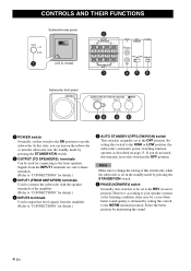
... (OFF/LOW/HIGH) switch This switch is originally set to the NORM (normal) position. model) 2 OUTPUT TO SPEAKERS R L R L FROM AMPLIFIER INPUT 1 3 INPUT AUTO PHASE 2 STANDBY L /MONO OFF LOWHIGH NORM REV R 45 6 Subwoofer front panel SUBWOOFER SYSTEM YST-RSW300 STANDBY/ON HIGH CUT VOLUME 78 40Hz 140Hz 9 0 10 0 1 POWER switch Normally, set in the OFF position...
... (OFF/LOW/HIGH) switch This switch is originally set to the NORM (normal) position. model) 2 OUTPUT TO SPEAKERS R L R L FROM AMPLIFIER INPUT 1 3 INPUT AUTO PHASE 2 STANDBY L /MONO OFF LOWHIGH NORM REV R 45 6 Subwoofer front panel SUBWOOFER SYSTEM YST-RSW300 STANDBY/ON HIGH CUT VOLUME 78 40Hz 140Hz 9 0 10 0 1 POWER switch Normally, set in the OFF position...
Owners Manual
Page 16
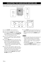
... other components. 3 Make sure that the POWER switch on page 14. 12 En model) 7 SUBWOOFER SYSTEM YST-RSW300 STANDBY/ON HIGH CUT VOLUME 40Hz 140Hz 0 10 3 5,6 1,6 Subwoofer front panel 1 Set the VOLUME control to minimum (0). 2 Turn on the power of your whole... sound system by using the subwoofer, adjust the subwoofer to obtain the optimum volume and tone balance between the subwoofer and the main speakers...
... other components. 3 Make sure that the POWER switch on page 14. 12 En model) 7 SUBWOOFER SYSTEM YST-RSW300 STANDBY/ON HIGH CUT VOLUME 40Hz 140Hz 0 10 3 5,6 1,6 Subwoofer front panel 1 Set the VOLUME control to minimum (0). 2 Turn on the power of your whole... sound system by using the subwoofer, adjust the subwoofer to obtain the optimum volume and tone balance between the subwoofer and the main speakers...
Owners Manual
Page 18
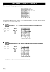
...characteristics when this subwoofer is combined with a typical main speaker system. ■ Example 1 When combined with a 4" or 5" (10 cm or 13 cm) acoustic suspension, 2 way system main speakers: HIGH CUT VOLUME 40Hz 140Hz 0 10 (70Hz) PHASE NORM REV (REV) dB 90 80 YST-RSW300 70 60 Main speaker 50 40 ...an 8" or 10" (20 cm or 25 cm) acoustic suspension, 2 way system main speakers: HIGH CUT VOLUME 40Hz 140Hz 0 10 (50Hz) PHASE NORM REV (REV) dB 90 80 YST-RSW300 70 60 Main speaker 50 40 20 50 100 200 500Hz Frequency response graph* *This diagram does not depict ...
...characteristics when this subwoofer is combined with a typical main speaker system. ■ Example 1 When combined with a 4" or 5" (10 cm or 13 cm) acoustic suspension, 2 way system main speakers: HIGH CUT VOLUME 40Hz 140Hz 0 10 (70Hz) PHASE NORM REV (REV) dB 90 80 YST-RSW300 70 60 Main speaker 50 40 ...an 8" or 10" (20 cm or 25 cm) acoustic suspension, 2 way system main speakers: HIGH CUT VOLUME 40Hz 140Hz 0 10 (50Hz) PHASE NORM REV (REV) dB 90 80 YST-RSW300 70 60 Main speaker 50 40 20 50 100 200 500Hz Frequency response graph* *This diagram does not depict ...


