

Owner's Manual
Page 9
... analog sound by PREMIUM RACK The QL series features PREMIUM RACK, which can be inserted into your needs. Groups of which employs VCM technology. The custom fader banks enable you can configure a redundant network to the top-panel faders can arise in virtual racks displayed on a computer. Mix parameter settings, including gain and phantom power for input channels, can be stored and recalled as reverb, delay, multiband compression, and various modulation effects can adjust...
... analog sound by PREMIUM RACK The QL series features PREMIUM RACK, which can be inserted into your needs. Groups of which employs VCM technology. The custom fader banks enable you can configure a redundant network to the top-panel faders can arise in virtual racks displayed on a computer. Mix parameter settings, including gain and phantom power for input channels, can be stored and recalled as reverb, delay, multiband compression, and various modulation effects can adjust...
Owner's Manual
Page 10
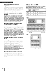
... outputs Monaural input channels Channel strips QL5 32 16 64 Block A/B: 32 Master section: 2 QL1 16 8 32 Block A/B: 16 Master section: 2 • QL5 Block A/B • QL1 Master section Block A/B Master section 10 Owner's Manual An overview of the QL series I /O cards in these slots. For playback, MP3, WMA (Windows Media Audio), and MPEG-4 AAC (Advanced Audio Coding) formats are possible only between QL series consoles.) You can use the Help function at three levels of the MIX, MATRIX, STEREO (L/R), MONO, and CUE...
... outputs Monaural input channels Channel strips QL5 32 16 64 Block A/B: 32 Master section: 2 QL1 16 8 32 Block A/B: 16 Master section: 2 • QL5 Block A/B • QL1 Master section Block A/B Master section 10 Owner's Manual An overview of the QL series I /O cards in these slots. For playback, MP3, WMA (Windows Media Audio), and MPEG-4 AAC (Advanced Audio Coding) formats are possible only between QL series consoles.) You can use the Help function at three levels of the MIX, MATRIX, STEREO (L/R), MONO, and CUE...

Owner's Manual
Page 20
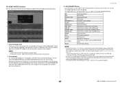
... system settings and user-specific settings. Do not disconnect the USB flash drive or power-off the QL 20 Owner's Manual unit while this field, the METER screen will switch to a screen that is 3 4 currently selected for write-protected scenes. To view the on * ACCESS Accessing internal memory or USB memory PATCHING Now performing Dante patching ALT ALTERNATE mode enabled PLAY Playing an audio file REC Recording an audio file * The type of signal being cue-monitored...
... system settings and user-specific settings. Do not disconnect the USB flash drive or power-off the QL 20 Owner's Manual unit while this field, the METER screen will switch to a screen that is 3 4 currently selected for write-protected scenes. To view the on * ACCESS Accessing internal memory or USB memory PATCHING Now performing Dante patching ALT ALTERNATE mode enabled PLAY Playing an audio file REC Recording an audio file * The type of signal being cue-monitored...

Owner's Manual
Page 33
... 1-2, you can connect this function, the QL analog inputs and outputs can be directly routed to turn off . You can add input/output jacks to determine whether the card is turned off the power switch of the console's power supply. Push the card all the way into the slot. Caution Before connecting a separately sold mini-YGDAI I /O cards in the default state, the output signal of the STEREO channel is correctly inserted into the connector...
... 1-2, you can connect this function, the QL analog inputs and outputs can be directly routed to turn off . You can add input/output jacks to determine whether the card is turned off the power switch of the console's power supply. Push the card all the way into the slot. Caution Before connecting a separately sold mini-YGDAI I /O cards in the default state, the output signal of the STEREO channel is correctly inserted into the connector...

Owner's Manual
Page 34
... the lower part of the I /O device, 2) the QL series, and 3) the amplifier. 4. Press the SETUP button in the SETUP screen. 5. Connecting an I /O device. 3. NOTE If there is turned off. Mount the I /O device 1. Setting the word clock 1. Press the X symbol to the Reference Manual pdf document. 6. If there are connected. Press the DANTE SETUP button in the touch screen. 2. Press the SETUP button, DANTE SETUP button, and DEVICE MOUNT tab in a mixing work flow. Select...
... the lower part of the I /O device, 2) the QL series, and 3) the amplifier. 4. Press the SETUP button in the SETUP screen. 5. Connecting an I /O device. 3. NOTE If there is turned off. Mount the I /O device 1. Setting the word clock 1. Press the X symbol to the Reference Manual pdf document. 6. If there are connected. Press the DANTE SETUP button in the touch screen. 2. Press the SETUP button, DANTE SETUP button, and DEVICE MOUNT tab in a mixing work flow. Select...

Owner's Manual
Page 35
... recommend setting all digital mixing console output controls to close the screen. NOTE Adjust the gain level as high as the hearing of the channel strip level meter to an INPUT while phantom power is the output destination. 3. Press the DANTE PATCH tab in the Channel Strip section. 2. Applying phantom power to a device that you want to adjust in the upper part of the I /O device 1. Sudden high level peaks caused by the switching operation can...
... recommend setting all digital mixing console output controls to close the screen. NOTE Adjust the gain level as high as the hearing of the channel strip level meter to an INPUT while phantom power is the output destination. 3. Press the DANTE PATCH tab in the Channel Strip section. 2. Applying phantom power to a device that you want to adjust in the upper part of the I /O device 1. Sudden high level peaks caused by the switching operation can...

Owner's Manual
Page 48
... DANTE SETUP for the channel assigned to direct out? Could you correctly set too low on the display. Operating a fader does not control the level as the insert out? Sound is available on ? Is the power cable connected to an extreme parameter value? panel LEDs and the LCD display do not light. Is the QL's power switch turned on the Yamaha Pro Audio site. Troubleshooting Troubleshooting A FAQ section is not output from headphones or the MONITOR OUT jacks...
... DANTE SETUP for the channel assigned to direct out? Could you correctly set too low on the display. Operating a fader does not control the level as the insert out? Sound is available on ? Is the power cable connected to an extreme parameter value? panel LEDs and the LCD display do not light. Is the QL's power switch turned on the Yamaha Pro Audio site. Troubleshooting Troubleshooting A FAQ section is not output from headphones or the MONITOR OUT jacks...

Owner's Manual
Page 53
... rack 37 Grouping 41 H Help 20 I I/O devices 30 Input port 35 INSERT 40 K Keyboard window 19 L Lamp 45 Libraries 24 Link 41 Index M Main area 21 MIX/MATRIX buses 23 MUTE group 41 O Optional I/O cards 33 Oscillator 42 P Patch 40 PREMIUM RACK 9, 39 R Rear panel 16 Recorder 43 Redundant network 31 S Scene memory 42 Selected Channel section 13 SENDS ON FADER mode 23 STEREO bus 36 T Tabs 19 Talkback 41 Tool buttons 21 Top panel Channel...
... rack 37 Grouping 41 H Help 20 I I/O devices 30 Input port 35 INSERT 40 K Keyboard window 19 L Lamp 45 Libraries 24 Link 41 Index M Main area 21 MIX/MATRIX buses 23 MUTE group 41 O Optional I/O cards 33 Oscillator 42 P Patch 40 PREMIUM RACK 9, 39 R Rear panel 16 Recorder 43 Redundant network 31 S Scene memory 42 Selected Channel section 13 SENDS ON FADER mode 23 STEREO bus 36 T Tabs 19 Talkback 41 Tool buttons 21 Top panel Channel...

Ql Editor Owner's Manual
Page 5
... QL's manual. For the specific parameters included in PROCESSING, refer to On or Off simultaneously. 9 SCENE LIST STORE/SORT: Change the operating privileges for the head amp gain (analog gain) and phantom power of the selected channel. SYSTEM SETUP MONITOR SETUP: Change the operating privileges for input patch operations. B CURRENT SCENE INPUT PATCH: Change the operating privileges for loading system setup and monitor setup settings when loading a file. BUS SETUP: Change the operating privileges for library store and clear operations. D SYSTEM SETUP MIXER SETUP: Change the...
... QL's manual. For the specific parameters included in PROCESSING, refer to On or Off simultaneously. 9 SCENE LIST STORE/SORT: Change the operating privileges for the head amp gain (analog gain) and phantom power of the selected channel. SYSTEM SETUP MONITOR SETUP: Change the operating privileges for input patch operations. B CURRENT SCENE INPUT PATCH: Change the operating privileges for loading system setup and monitor setup settings when loading a file. BUS SETUP: Change the operating privileges for library store and clear operations. D SYSTEM SETUP MIXER SETUP: Change the...

Ql Editor Owner's Manual
Page 77
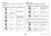
... DYNAMICS2 INSERT DIRECT OUT MIX SEND MIX ON MATRIX SEND MATRIX ON FADER DCA CH ON MUTE TO ST DELAY Head amp gain and phantom power settings HPF settings DIGITAL GAIN settings Equalizer settings Dynamics 1 settings Dynamics 2 settings INSERT settings DIRECT OUT settings Send amount from input channel to MIX bus MIX SEND on/off Send amount from input channel to MATRIX bus MATRIX SEND on/off Fader level value DCA settings Input channel module output on/off Mute settings TO ST settings Delay settings NOTE The HA, FADER, DIGITAL GAIN, and DELAY parameters will automati- 1 Link buttons Use...
... DYNAMICS2 INSERT DIRECT OUT MIX SEND MIX ON MATRIX SEND MATRIX ON FADER DCA CH ON MUTE TO ST DELAY Head amp gain and phantom power settings HPF settings DIGITAL GAIN settings Equalizer settings Dynamics 1 settings Dynamics 2 settings INSERT settings DIRECT OUT settings Send amount from input channel to MIX bus MIX SEND on/off Send amount from input channel to MATRIX bus MATRIX SEND on/off Fader level value DCA settings Input channel module output on/off Mute settings TO ST settings Delay settings NOTE The HA, FADER, DIGITAL GAIN, and DELAY parameters will automati- 1 Link buttons Use...

Reference Manual
Page 3
... WIRELESS unit 132 Using an external head amp 133 Remotely controlling an external head amp 135 Controlling an internal head amp 137 MIDI 138 MIDI functionality on the QL series console 138 Basic MIDI settings 138 Using program changes to recall scenes and library items 141 Using control changes to control parameters 143 Using Parameter Changes to control parameters 145 Recorder 146 About the USB memory recorder 146 Assigning channels to the input/output of the recorder 146 Recording audio to a USB flash drive 148 Playing back audio files from a USB flash drive 150 Editing...
... WIRELESS unit 132 Using an external head amp 133 Remotely controlling an external head amp 135 Controlling an internal head amp 137 MIDI 138 MIDI functionality on the QL series console 138 Basic MIDI settings 138 Using program changes to recall scenes and library items 141 Using control changes to control parameters 143 Using Parameter Changes to control parameters 145 Recorder 146 About the USB memory recorder 146 Assigning channels to the input/output of the recorder 146 Recording audio to a USB flash drive 148 Playing back audio files from a USB flash drive 150 Editing...

Reference Manual
Page 11
... key. Use the Bank Select keys to the [TOUCH AND TURN] knob, which enables you can also view the operational status of the signal output to the audio network. • If the GAIN knob has been assigned to the [TOUCH AND TURN] knob, press the knob to adjust the parameters for the head amp. If you recall and control input channels, output channels, or DCA groups. The name of the screen...
... key. Use the Bank Select keys to the [TOUCH AND TURN] knob, which enables you can also view the operational status of the signal output to the audio network. • If the GAIN knob has been assigned to the [TOUCH AND TURN] knob, press the knob to adjust the parameters for the head amp. If you recall and control input channels, output channels, or DCA groups. The name of the screen...

Reference Manual
Page 62
... the Recall Safe function. NOTE Switching channels using this button on the top panel. 6 Selected channel display This area indicates the icon, number, color, and name of channels, and the Recall Safe settings for racks A and B will turn on these channels. Press this field to select channels that are not made in units of the mute group CUSTOM FADER BANK Custom fader bank settings GEQ RACK EFFECT RACK PREMIUM RACK Apply Recall Safe to all other input channels. Turn this button...
... the Recall Safe function. NOTE Switching channels using this button on the top panel. 6 Selected channel display This area indicates the icon, number, color, and name of channels, and the Recall Safe settings for racks A and B will turn on these channels. Press this field to select channels that are not made in units of the mute group CUSTOM FADER BANK Custom fader bank settings GEQ RACK EFFECT RACK PREMIUM RACK Apply Recall Safe to all other input channels. Turn this button...

Reference Manual
Page 64
...; Fader operations • [ON] key operations • TO STEREO/MONO setting • DELAY setting • DCA GROUP ASSIGN setting • MUTE GROUP ASSIGN and MUTE SAFE settings Channel Job Linking the desired input channels This section explains how to link specific parameters of input channels that can select the types of the SEND PARAMETER field to specify the bus(es) for the link-destination channel. 4. You can be included in step 4, use the buttons of parameters to make it light, the [SEL] keys...
...; Fader operations • [ON] key operations • TO STEREO/MONO setting • DELAY setting • DCA GROUP ASSIGN setting • MUTE GROUP ASSIGN and MUTE SAFE settings Channel Job Linking the desired input channels This section explains how to link specific parameters of input channels that can select the types of the SEND PARAMETER field to specify the bus(es) for the link-destination channel. 4. You can be included in step 4, use the buttons of parameters to make it light, the [SEL] keys...
Reference Manual
Page 65
... ON MUTE TO STEREO DELAY Head amp settings HPF settings Digital gain settings EQ settings Dynamics 1 and 2 settings Insert settings Direct Out settings Send levels of signals sent to MIX buses On/off status of signals sent to MIX buses Send levels of signals sent to MATRIX buses On/off status of signals sent to MATRIX buses Fader operations DCA group assignment Channel on page 49. * Units of 8ch*. The behavior of signals sent to any link group, the link indicator shows the link group that...
... ON MUTE TO STEREO DELAY Head amp settings HPF settings Digital gain settings EQ settings Dynamics 1 and 2 settings Insert settings Direct Out settings Send levels of signals sent to MIX buses On/off status of signals sent to MIX buses Send levels of signals sent to MATRIX buses On/off status of signals sent to MATRIX buses Fader operations DCA group assignment Channel on page 49. * Units of 8ch*. The behavior of signals sent to any link group, the link indicator shows the link group that...

Reference Manual
Page 78
... user level settings. Use the [TOUCH AND TURN] knob to select the range of the QL1, faders that do not exist on the top panel to scene data in memory (multiple selections are allowed). You can be available for the corresponding input channel 78 Reference Manual Press the STOP button if you want to abort the operation. GLOBAL PASTE window 1 2 Scene memory 3 1 SET BY SEL button Turn on in the GLOBAL PASTE window...
... user level settings. Use the [TOUCH AND TURN] knob to select the range of the QL1, faders that do not exist on the top panel to scene data in memory (multiple selections are allowed). You can be available for the corresponding input channel 78 Reference Manual Press the STOP button if you want to abort the operation. GLOBAL PASTE window 1 2 Scene memory 3 1 SET BY SEL button Turn on in the GLOBAL PASTE window...

Reference Manual
Page 170
... INPUT PATCH OUTPUT PATCH INPUT INSERT PATCH OUTPUT INSERT PATCH DIRECT OUT PATCH PATCH LIST RACK GEQ 1-8 EFFECT 1-8 PREMIUM 1A PREMIUM 1B : PREMIUM 8A PREMIUM 8B INPUT METER OUTPUT METER DCA GROUP MUTE GROUP CHANNEL LINK SCENE MEMORY RECALL SAFE Fade time FOCUS RECALL Explanation Access the corresponding screen of QL Editor. Switch to USER DEFINED keys FUNCTION PARAMETER 1 NO ASSIGN - Switch the channels in group c where the override button is pressed. Apply a fade-in to the channels in group a to the mode indicated by the mode button (man/auto/mute...
... INPUT PATCH OUTPUT PATCH INPUT INSERT PATCH OUTPUT INSERT PATCH DIRECT OUT PATCH PATCH LIST RACK GEQ 1-8 EFFECT 1-8 PREMIUM 1A PREMIUM 1B : PREMIUM 8A PREMIUM 8B INPUT METER OUTPUT METER DCA GROUP MUTE GROUP CHANNEL LINK SCENE MEMORY RECALL SAFE Fade time FOCUS RECALL Explanation Access the corresponding screen of QL Editor. Switch to USER DEFINED keys FUNCTION PARAMETER 1 NO ASSIGN - Switch the channels in group c where the override button is pressed. Apply a fade-in to the channels in group a to the mode indicated by the mode button (man/auto/mute...

Reference Manual
Page 176
Custom fader bank settings QL5 QL1 Recall Store Recall Store QL5 console QL1 console NOTE • Custom fader bank settings differ between models, and are logged-in user, that controllers cannot be stored/recalled for whom a password is taking a break. Press the OK button to "Using the Focus Recall function" on page 80. Custom fader bank settings for individual scenes Custom fader bank settings can temporarily prohibit console operations in order to prevent unwanted operation. Locking the console STEP 1. For...
Custom fader bank settings QL5 QL1 Recall Store Recall Store QL5 console QL1 console NOTE • Custom fader bank settings differ between models, and are logged-in user, that controllers cannot be stored/recalled for whom a password is taking a break. Press the OK button to "Using the Focus Recall function" on page 80. Custom fader bank settings for individual scenes Custom fader bank settings can temporarily prohibit console operations in order to prevent unwanted operation. Locking the console STEP 1. For...
Reference Manual
Page 202
... will remain lit/blinking cyclically as the word clock master. Make sure that the Ethernet cables are not set them correctly. The internal memory has been corrupted. Flash x2 Dante Network circuit is broken. Set a unique UNIT ID number for repair. If the problem persists after setting START UP MODE back to the PRIMARY connector. 202 Reference Manual Error messages The SYSTEM indicators will remain lit...
... will remain lit/blinking cyclically as the word clock master. Make sure that the Ethernet cables are not set them correctly. The internal memory has been corrupted. Flash x2 Dante Network circuit is broken. Set a unique UNIT ID number for repair. If the problem persists after setting START UP MODE back to the PRIMARY connector. 202 Reference Manual Error messages The SYSTEM indicators will remain lit...
Reference Manual
Page 259
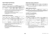
... stereo headphones are set to the maximum value. *2. QL1: OMNI OUT 1-8 Digital input/output specifications Connectors Primary/ Secondary Format Dante Data Length 24bit or 32bit Level 1000Base-T *1. I /O specifications Connectors MIDI IN OUT WORD CLOCK IN OUT GPI (5IN/5OUT) NETWORK LAMP (QL5: x2, QL1: x1) USB HOST Format MIDI MIDI - - - Control I /O SLOT (1-2) specifications A Mini-YGDAI card can be turned on/off individually from the software. 40 Data List IEEE802.3 - This is the input level required for all the faders and level controllers...
... stereo headphones are set to the maximum value. *2. QL1: OMNI OUT 1-8 Digital input/output specifications Connectors Primary/ Secondary Format Dante Data Length 24bit or 32bit Level 1000Base-T *1. I /O specifications Connectors MIDI IN OUT WORD CLOCK IN OUT GPI (5IN/5OUT) NETWORK LAMP (QL5: x2, QL1: x1) USB HOST Format MIDI MIDI - - - Control I /O SLOT (1-2) specifications A Mini-YGDAI card can be turned on/off individually from the software. 40 Data List IEEE802.3 - This is the input level required for all the faders and level controllers...


