

Owner's Manual
Page 1
U B NS-P320 (Including SW-P201 subwoofer system) HOME CINEMA 5.1CH SPEAKER PACKAGE OWNER'S MANUAL I
U B NS-P320 (Including SW-P201 subwoofer system) HOME CINEMA 5.1CH SPEAKER PACKAGE OWNER'S MANUAL I
Owner's Manual
Page 2
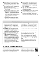
REFER SERVICING TO QUALIFIED SERVICE PERSONNEL. IMPORTANT Please record the serial number of this system in the cabinet are unable to lightning and power-line surges. 15 Power Lines - Model: Serial No.: The serial number is operated. 2 Retain Instructions - The safety and operating instructions should be adhered to operate from the wall outlet before the product is located on a bed, sofa, rug, or other ). Do not use liquid cleaners or aerosol cleaners. for cleaning. 6 Attachments - or near water - The product may cause hazards. 7 Water and Moisture - For ...
REFER SERVICING TO QUALIFIED SERVICE PERSONNEL. IMPORTANT Please record the serial number of this system in the cabinet are unable to lightning and power-line surges. 15 Power Lines - Model: Serial No.: The serial number is operated. 2 Retain Instructions - The safety and operating instructions should be adhered to operate from the wall outlet before the product is located on a bed, sofa, rug, or other ). Do not use liquid cleaners or aerosol cleaners. for cleaning. 6 Attachments - or near water - The product may cause hazards. 7 Water and Moisture - For ...
Owner's Manual
Page 3
... devices. Follow all installations. The above statements apply ONLY to avoid prolonged exposure from loud sounds is too late, YAMAHA and the Electronic Industries Association's Consumer Electronics Group recommend you to the operation of radio or TV interference, relocate/reorient... the antenna. Do not attempt to qualified service personnel. 19 Damage Requiring Service - Modifications not expressly approved by Yamaha may result in to follow instructions could void your equipment by following the operating instructions. this product in fire, electric ...
... devices. Follow all installations. The above statements apply ONLY to avoid prolonged exposure from loud sounds is too late, YAMAHA and the Electronic Industries Association's Consumer Electronics Group recommend you to the operation of radio or TV interference, relocate/reorient... the antenna. Do not attempt to qualified service personnel. 19 Damage Requiring Service - Modifications not expressly approved by Yamaha may result in to follow instructions could void your equipment by following the operating instructions. this product in fire, electric ...
Owner's Manual
Page 4
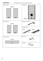
UNPACKING After unpacking, check that the following items are contained. G Main speakers G Subwoofer G Rear speakers G Center speaker G Audio connection cable G Speaker cables [4m] [15m] X 3 X 2 G Fastener X 4 G Pads IV
UNPACKING After unpacking, check that the following items are contained. G Main speakers G Subwoofer G Rear speakers G Center speaker G Audio connection cable G Speaker cables [4m] [15m] X 3 X 2 G Fastener X 4 G Pads IV
Owner's Manual
Page 5
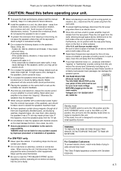
... may cause damage to the speakers, and/or you note distortion, reduce the volume control on the both sides of the unit to read this YAMAHA NS-P320 Speaker Package. In such a case, move the speakers away from the rear panel. WARNING TO REDUCE THE RISK OF FIRE OR ELECTRIC SHOCK, DO NOT...
... may cause damage to the speakers, and/or you note distortion, reduce the volume control on the both sides of the unit to read this YAMAHA NS-P320 Speaker Package. In such a case, move the speakers away from the rear panel. WARNING TO REDUCE THE RISK OF FIRE OR ELECTRIC SHOCK, DO NOT...
Owner's Manual
Page 6
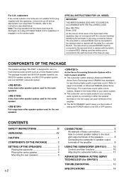
...for the rear speakers Active Servo Processing Subwoofer System with a built-in power amplifier ● This subwoofer system employs Advanced YAMAHA Active Servo Technology which YAMAHA has developed for the plug supplied with this apparatus may not correspond with the letter N or coloured BLACK. MODEL IMPORTANT...flexible cord is coloured BROWN must be cut off and an appropriate 3 pin plug fitted. COMPONENTS OF THE PACKAGE The speaker package "NS-P320" is coloured BLUE must be connected to speaker output terminals of the three pin plug. For details, refer to the earth terminal...
...for the rear speakers Active Servo Processing Subwoofer System with a built-in power amplifier ● This subwoofer system employs Advanced YAMAHA Active Servo Technology which YAMAHA has developed for the plug supplied with this apparatus may not correspond with the letter N or coloured BLACK. MODEL IMPORTANT...flexible cord is coloured BROWN must be cut off and an appropriate 3 pin plug fitted. COMPONENTS OF THE PACKAGE The speaker package "NS-P320" is coloured BLUE must be connected to speaker output terminals of the three pin plug. For details, refer to the earth terminal...
Owner's Manual
Page 7
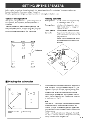
About 1.8 m (approx. 6 feet) from the subwoofer when listening in fig. Å. It also may be necessary to "Placing the subwoofer" below . SETTING UP THE SPEAKERS Before making connections, place all speakers in fig. ı is also possible, however, if the subwoofer system is for reinforcing low frequencies on the outside of the subwoofer. The positioning of the speakers is important because it and the sound reflected by placing bookshelves etc. Subwoofer: The position of this from it controls the whole sound quality of the subwoofer is not so critical because ...
About 1.8 m (approx. 6 feet) from the subwoofer when listening in fig. Å. It also may be necessary to "Placing the subwoofer" below . SETTING UP THE SPEAKERS Before making connections, place all speakers in fig. ı is also possible, however, if the subwoofer system is for reinforcing low frequencies on the outside of the subwoofer. The positioning of the speakers is important because it and the sound reflected by placing bookshelves etc. Subwoofer: The position of this from it controls the whole sound quality of the subwoofer is not so critical because ...
Owner's Manual
Page 8
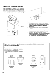
If placed, the speaker may cause the center speaker to be used to prevent the speaker from falling down, put the provided fasteners at four points on the bottom of the speaker and the top of the TV, to mount the speaker on a speaker stand. * Those screw holes can be used with M4 screws only. 60 mm 60 mm 60 mm 60 mm Main speaker (bottom) Rear speaker (bottom) E-4 Main speaker (rear) Rear speaker (rear) Note that adhesive strength is weakened if the surface is dirty, oily or wet and that it is stabilized. Ⅵ Placing the center speaker Place the speaker on TV whose ...
If placed, the speaker may cause the center speaker to be used to prevent the speaker from falling down, put the provided fasteners at four points on the bottom of the speaker and the top of the TV, to mount the speaker on a speaker stand. * Those screw holes can be used with M4 screws only. 60 mm 60 mm 60 mm 60 mm Main speaker (bottom) Rear speaker (bottom) E-4 Main speaker (rear) Rear speaker (rear) Note that adhesive strength is weakened if the surface is dirty, oily or wet and that it is stabilized. Ⅵ Placing the center speaker Place the speaker on TV whose ...

Owner's Manual
Page 9
Do not mount them to fall . Longterm use the lower holes on the rear of the flimsy surface and the speakers may cause them on thin plywood or a wall with nails, adhesives, or any other unstable hardware. E-5 This damages the speakers or causes personal injury. ● Do not install the speakers to a wall with soft surface material. If mounted, the screws may come out of the rear 3 speakers. 60 mm WARNING ● Each speaker weighs 1.1 kg (2 lbs. 6 oz.). Holes To mount the rear speakers on a wall by vibrations. 2 Fasten screws into a firm wall or wall support as shown...
Do not mount them to fall . Longterm use the lower holes on the rear of the flimsy surface and the speakers may cause them on thin plywood or a wall with nails, adhesives, or any other unstable hardware. E-5 This damages the speakers or causes personal injury. ● Do not install the speakers to a wall with soft surface material. If mounted, the screws may come out of the rear 3 speakers. 60 mm WARNING ● Each speaker weighs 1.1 kg (2 lbs. 6 oz.). Holes To mount the rear speakers on a wall by vibrations. 2 Fasten screws into a firm wall or wall support as shown...
Owner's Manual
Page 10
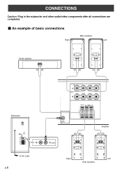
SUB WOOFER OUTPUT Amplifier /MONO Right Left Rear speakers CONNECTIONS Caution: Plug in the subwoofer and other audio/video components after all connections are completed. Ⅵ An example of basic connections Main speakers Right Left Center speaker Subwoofer POWER ON OFF VOLUME STANDBY-RED ON-GREEN AUTO STANDBY HIGH LOW OFF 0 I0 INPUT2 /MONO INPUT1 FROM AMPLIFIER OUTPUT TO SPEAKERS INPUT2 To AC outlet E-6 R+ A SPEAKERS - - +L MAIN B IMPEDA EO SET B MA CENTER REAR R (SURROUND) L CEN RE + MAIN A OR B: 4 M A + B: 8 M CENTER : 6 M REAR :6 M -
SUB WOOFER OUTPUT Amplifier /MONO Right Left Rear speakers CONNECTIONS Caution: Plug in the subwoofer and other audio/video components after all connections are completed. Ⅵ An example of basic connections Main speakers Right Left Center speaker Subwoofer POWER ON OFF VOLUME STANDBY-RED ON-GREEN AUTO STANDBY HIGH LOW OFF 0 I0 INPUT2 /MONO INPUT1 FROM AMPLIFIER OUTPUT TO SPEAKERS INPUT2 To AC outlet E-6 R+ A SPEAKERS - - +L MAIN B IMPEDA EO SET B MA CENTER REAR R (SURROUND) L CEN RE + MAIN A OR B: 4 M A + B: 8 M CENTER : 6 M REAR :6 M -
Owner's Manual
Page 11
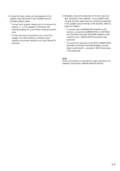
... not have any line output terminal, connect the subwoofer to the speaker output terminals of the amplifier. (Refer to page 9 for details.) * To connect with a YAMAHA DSP amplifier (or AV receiver), connect the SUBWOOFER (or LOW PASS etc.) terminal on the rear of the DSP amplifier (or AV receiver) to the...
... not have any line output terminal, connect the subwoofer to the speaker output terminals of the amplifier. (Refer to page 9 for details.) * To connect with a YAMAHA DSP amplifier (or AV receiver), connect the SUBWOOFER (or LOW PASS etc.) terminal on the rear of the DSP amplifier (or AV receiver) to the...
Owner's Manual
Page 12
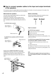
... terminals on both the subwoofer and the amplifier using one side of each other side has no line. Test the firmness of them. For NS-M104 (main speaker) Red: positive (+) Black: negative (-) 1 How to the input and output terminals of the cables. Note Do not ... the coating off. Before connecting Remove the insulation coating at the extremity of the cable. Red: positive (+) Black: negative (-) E-8 For NS-E104 (rear speaker), NS-C104 (center speaker) and subwoofer's INPUT 1/OUTPUT terminals 1 Press and hold the terminal's tab, as this could damage the speaker or ...
... terminals on both the subwoofer and the amplifier using one side of each other side has no line. Test the firmness of them. For NS-M104 (main speaker) Red: positive (+) Black: negative (-) 1 How to the input and output terminals of the cables. Note Do not ... the coating off. Before connecting Remove the insulation coating at the extremity of the cable. Red: positive (+) Black: negative (-) E-8 For NS-E104 (rear speaker), NS-C104 (center speaker) and subwoofer's INPUT 1/OUTPUT terminals 1 Press and hold the terminal's tab, as this could damage the speaker or ...
Owner's Manual
Page 13
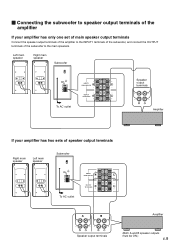
Ⅵ Connecting the subwoofer to speaker output terminals of the amplifier If your amplifier has two sets of the subwoofer to the INPUT1 terminals of the subwoofer, and connect the OUTPUT terminals of speaker output terminals Right main speaker Left main speaker Subwoofer POWER ON OFF VOLUME STANDBY-RED ON-GREEN AUTO STANDBY HIGH LOW OFF 0 I0 INPUT2 /MONO INPUT1 FROM AMPLIFIER OUTPUT TO SPEAKERS To AC outlet INPUT1 FROM AMPLIFIER OUTPUT TO SPEAKERS A B Amplifier Speaker output terminals (Both A and B speaker outputs must be ON.) E-9 Left main speaker Right main ...
Ⅵ Connecting the subwoofer to speaker output terminals of the amplifier If your amplifier has two sets of the subwoofer to the INPUT1 terminals of the subwoofer, and connect the OUTPUT terminals of speaker output terminals Right main speaker Left main speaker Subwoofer POWER ON OFF VOLUME STANDBY-RED ON-GREEN AUTO STANDBY HIGH LOW OFF 0 I0 INPUT2 /MONO INPUT1 FROM AMPLIFIER OUTPUT TO SPEAKERS To AC outlet INPUT1 FROM AMPLIFIER OUTPUT TO SPEAKERS A B Amplifier Speaker output terminals (Both A and B speaker outputs must be ON.) E-9 Left main speaker Right main ...
Owner's Manual
Page 14
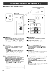
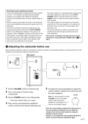
Turn the control clockwise to increase the volume, and counterclockwise to decrease the volume. 8 VOLTAGE SELECTOR switch (General model only) If the preset setting of the switch is incorrect, set the switch to the proper voltage range (220V-240V or 110V-120V) of your dealer if you do not need this function, set to the HIGH or LOW position, this indicator lights up GREEN. Consult your area. Set this switch to the OFF position to turn on the power of the subwoofer. Signals from the amplifier. 5 INPUT1 (FROM AMPLIFIER) terminals Used to connect the subwoofer with the speaker terminals...
Turn the control clockwise to increase the volume, and counterclockwise to decrease the volume. 8 VOLTAGE SELECTOR switch (General model only) If the preset setting of the switch is incorrect, set the switch to the proper voltage range (220V-240V or 110V-120V) of your dealer if you do not need this function, set to the HIGH or LOW position, this indicator lights up GREEN. Consult your area. Set this switch to the OFF position to turn on the power of the subwoofer. Signals from the amplifier. 5 INPUT1 (FROM AMPLIFIER) terminals Used to connect the subwoofer with the speaker terminals...
Owner's Manual
Page 15
... sound system by using the amplifier's volume control. However, if the power is an extremely low input signal. * The power might change the main speakers NS-M104 to others, you must make this package in green. 4 Play a source and adjust the amplifier's volume control to the desired listening level. 5 Increase the...
... sound system by using the amplifier's volume control. However, if the power is an extremely low input signal. * The power might change the main speakers NS-M104 to others, you must make this package in green. 4 Play a source and adjust the amplifier's volume control to the desired listening level. 5 Increase the...
Owner's Manual
Page 16
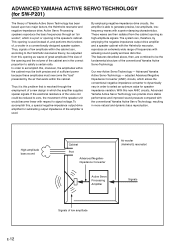
...signal voltage. By employing negative-impedance drive circuits, the amplifier is used instead of, and performs the functions of Yamaha Active Servo Technology has been based upon two major factors, the Helmholtz resonator and negative-impedance drive. High-amplitude bass... sound Cabinet Port Advanced Negativeimpedance Converter Active Servo Processing Amplifier Air woofer (Helmholtz resonator) Signals Signals of the conventional Yamaha Active Servo Technology. In order to accomplish this problem that exists within the cabinet can provide more natural and dynamic...
...signal voltage. By employing negative-impedance drive circuits, the amplifier is used instead of, and performs the functions of Yamaha Active Servo Technology has been based upon two major factors, the Helmholtz resonator and negative-impedance drive. High-amplitude bass... sound Cabinet Port Advanced Negativeimpedance Converter Active Servo Processing Amplifier Air woofer (Helmholtz resonator) Signals Signals of the conventional Yamaha Active Servo Technology. In order to accomplish this problem that exists within the cabinet can provide more natural and dynamic...
Owner's Manual
Page 17
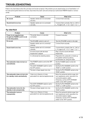
... away from external appliances etc. Set the AUTO STANDBY switch to the chart below do not help, disconnect the power cord and contact your authorized YAMAHA dealer or service center. Cause The power plug is too low. Sound level is not listed below or if the instructions given below when this...
... away from external appliances etc. Set the AUTO STANDBY switch to the chart below do not help, disconnect the power cord and contact your authorized YAMAHA dealer or service center. Cause The power plug is too low. Sound level is not listed below or if the instructions given below when this...
Owner's Manual
Page 18
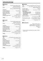
...H x D 440 x 85 x 122 mm (17-5/16" x 3-5/16" x 4-13/16") Weight 1.7 kg (3 lbs. 11 oz.) Ⅵ SW-P201 Type Advanced Yamaha Active Servo Technology Driver 16 cm (6-5/16") cone woofer (JA1678) Magnetic shielding type Amplifier Output 50W/5Ω Frequency Response 30 Hz-200 Hz (-10 dB...dB/2.83V/m Dimensions (W x H x D 140 x 300 x 167 mm (5-1/2" x 11-13/16" x 6-9/16") Weight 1.9 kg (4 lbs. 3 oz.) Ⅵ NS-C104 Type 2-way bass-reflex speaker system Magnetic shielding type Driver 7 cm (2-3/4") cone woofer x 3 1.5 cm (5/8") tweeter Impedance 6Ω Frequency Response 95 Hz to 20 kHz...
...H x D 440 x 85 x 122 mm (17-5/16" x 3-5/16" x 4-13/16") Weight 1.7 kg (3 lbs. 11 oz.) Ⅵ SW-P201 Type Advanced Yamaha Active Servo Technology Driver 16 cm (6-5/16") cone woofer (JA1678) Magnetic shielding type Amplifier Output 50W/5Ω Frequency Response 30 Hz-200 Hz (-10 dB...dB/2.83V/m Dimensions (W x H x D 140 x 300 x 167 mm (5-1/2" x 11-13/16" x 6-9/16") Weight 1.9 kg (4 lbs. 3 oz.) Ⅵ NS-C104 Type 2-way bass-reflex speaker system Magnetic shielding type Driver 7 cm (2-3/4") cone woofer x 3 1.5 cm (5/8") tweeter Impedance 6Ω Frequency Response 95 Hz to 20 kHz...

Owner's Manual
Page 19
.... 135 MILNER AVE., SCARBOROUGH, ONTARIO M1S 3R1, CANADA YAMAHA ELECTRONIK EUROPA G.m.b.H. RUE AMBROISE CROIZAT BP70 CROISSY-BEAUBOURG 77312 MARNE-LA-VALLEE CEDEX02, FRANCE YAMAHA ELECTRONICS (UK) LTD. YAMAHA HOUSE, 200 RICKMANSWORTH ROAD WATFORD, HERTS WD1 7JS, ENGLAND YAMAHA SCANDINAVIA A.B. SIEMENSSTR, 22-34, 25462 RELLINGEN, BEI HAMBURG, F.R. YAMAHA ELECTRONICS CORPORATION, USA 6660 ORANGETHORPE AVE., BUENA PARK...
.... 135 MILNER AVE., SCARBOROUGH, ONTARIO M1S 3R1, CANADA YAMAHA ELECTRONIK EUROPA G.m.b.H. RUE AMBROISE CROIZAT BP70 CROISSY-BEAUBOURG 77312 MARNE-LA-VALLEE CEDEX02, FRANCE YAMAHA ELECTRONICS (UK) LTD. YAMAHA HOUSE, 200 RICKMANSWORTH ROAD WATFORD, HERTS WD1 7JS, ENGLAND YAMAHA SCANDINAVIA A.B. SIEMENSSTR, 22-34, 25462 RELLINGEN, BEI HAMBURG, F.R. YAMAHA ELECTRONICS CORPORATION, USA 6660 ORANGETHORPE AVE., BUENA PARK...