
Owner's Manual
Page 2
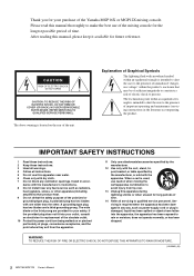
... MOISTURE. (UL60065_03) 2 MGP16X/MGP12X Owner's Manual IMPORTANT SAFETY INSTRUCTIONS 1 Read these instructions. 2 Keep these instructions. 3 Heed all warnings. 4 Follow all servicing to the presence of the unit. Install in any heat sources such as power-supply cord or plug is intended to alert the user to qualified service personnel. Please read this manual, please keep it available for future reference. Servicing is used, use of the mixing console for the...
... MOISTURE. (UL60065_03) 2 MGP16X/MGP12X Owner's Manual IMPORTANT SAFETY INSTRUCTIONS 1 Read these instructions. 2 Keep these instructions. 3 Heed all warnings. 4 Follow all servicing to the presence of the unit. Install in any heat sources such as power-supply cord or plug is intended to alert the user to qualified service personnel. Please read this manual, please keep it available for future reference. Servicing is used, use of the mixing console for the...
Owner's Manual
Page 3
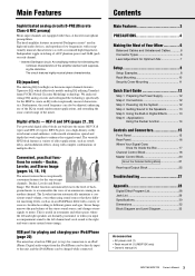
... is useful in Digital Effects 13 Step 6 Using the Ducker function 14 Controls and Connectors 15 Front Panel 15 Rear Panel 16 Where Your Signal Goes Once It's Inside the Box 17 Channel Control Block 18 Master Control Block 20 About the Detailed Setting Mode 21 Rear Input/Output Block 25 Troubleshooting 27 Appendix 28 Digital Effect Program List 28 Jack List 29 Specifications 30 Dimensions 32 Block Diagram and Level Diagram 33 Accessories • AC power cord (1) • Rack mount kit (1) (MGP12X only) • Owner's manual (1) MGP16X/MGP12X Owner's Manual 3 Contents Main...
... is useful in Digital Effects 13 Step 6 Using the Ducker function 14 Controls and Connectors 15 Front Panel 15 Rear Panel 16 Where Your Signal Goes Once It's Inside the Box 17 Channel Control Block 18 Master Control Block 20 About the Detailed Setting Mode 21 Rear Input/Output Block 25 Troubleshooting 27 Appendix 28 Digital Effect Program List 28 Jack List 29 Specifications 30 Dimensions 32 Block Diagram and Level Diagram 33 Accessories • AC power cord (1) • Rack mount kit (1) (MGP12X only) • Owner's manual (1) MGP16X/MGP12X Owner's Manual 3 Contents Main...
Owner's Manual
Page 4
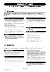
... or other devices, turn off the power immediately and unplug the power cord from the AC outlet. Then have the device inspected by qualified Yamaha service personnel. • Never insert or remove an electric plug with a protective grounding connection. This device has ventilation holes at the minimum level. If some trouble or malfunction occurs, immediately turn off the power switch and disconnect the electric...
... or other devices, turn off the power immediately and unplug the power cord from the AC outlet. Then have the device inspected by qualified Yamaha service personnel. • Never insert or remove an electric plug with a protective grounding connection. This device has ventilation holes at the minimum level. If some trouble or malfunction occurs, immediately turn off the power switch and disconnect the electric...
Owner's Manual
Page 5
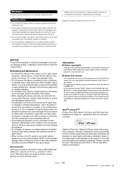
... the buttons, switches or connectors. • Do not use speakers or headphones for the same reason. Connectors XLR-type connectors are wired as shown in ambient temperature-when the device is lost or destroyed. Insert TRS phone jacks are trademarks of malfunction/damage to the product, damage to data, or damage to their respective companies. PA_en_1 2/2 MGP16X/MGP12X Owner's Manual...
... the buttons, switches or connectors. • Do not use speakers or headphones for the same reason. Connectors XLR-type connectors are wired as shown in ambient temperature-when the device is lost or destroyed. Insert TRS phone jacks are trademarks of malfunction/damage to the product, damage to data, or damage to their respective companies. PA_en_1 2/2 MGP16X/MGP12X Owner's Manual...
Owner's Manual
Page 6
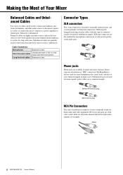
Short line-level cables Unbalanced cable is best. Male Female Phone jacks Phone jacks are a common example. Unbalanced types are used for mono signals -guitar cables are available in mono and stereo versions. White Red 6 MGP16X/MGP12X Owner's Manual XLR type connectors are the standard for microphone connections as well as "TRS" connectors (Tip-Ring-Sleeve), and are used for stereo headphone jacks, insert jacks, and also to carry balanced signals in a relatively noise-free environment. Stereo types...
Short line-level cables Unbalanced cable is best. Male Female Phone jacks Phone jacks are a common example. Unbalanced types are used for mono signals -guitar cables are available in mono and stereo versions. White Red 6 MGP16X/MGP12X Owner's Manual XLR type connectors are the standard for microphone connections as well as "TRS" connectors (Tip-Ring-Sleeve), and are used for stereo headphone jacks, insert jacks, and also to carry balanced signals in a relatively noise-free environment. Stereo types...
Owner's Manual
Page 7
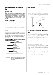
... while recording is simply to use as little equalization as handling noise, or rumble transmitted via the microphone stand. Or you can boost the bass a little if you 're mixing a piano trio with the clarity of other instruments. When an MGP high-pass filter is playing solo. Start with the Featured Part You can also be applied to guitar tracks...
... while recording is simply to use as little equalization as handling noise, or rumble transmitted via the microphone stand. Or you can boost the bass a little if you 're mixing a piano trio with the clarity of other instruments. When an MGP high-pass filter is playing solo. Start with the Featured Part You can also be applied to guitar tracks...
Owner's Manual
Page 12
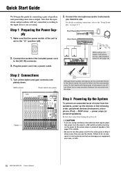
... use a DI box (direct box) or amp simulator between the instrument and the mixer. When using condenser microphones that require phantom power, turn the power on pages 8, 9. GAIN controls Power switch (rear panel) DI Although electric guitars and basses can damage your equipment, your ears, or both. 12 MGP16X/MGP12X Owner's Manual Reverse this guide by connecting a pair of speakers and generating some stereo output. CAUTION • If you are using. Step 1 Preparing the Power Supply 1. Connect the microphones...
... use a DI box (direct box) or amp simulator between the instrument and the mixer. When using condenser microphones that require phantom power, turn the power on pages 8, 9. GAIN controls Power switch (rear panel) DI Although electric guitars and basses can damage your equipment, your ears, or both. 12 MGP16X/MGP12X Owner's Manual Reverse this guide by connecting a pair of speakers and generating some stereo output. CAUTION • If you are using. Step 1 Preparing the Power Supply 1. Connect the microphones...
Owner's Manual
Page 13
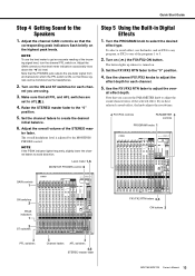
NOTE To use the level meter to the Speakers 1. Adjust the channel GAIN controls so that level meter indication occasionally rises above the " Adjust the GAIN controls so that the corresponding peak indicators flash briefly on . Quick Start Guide Step 4 Getting Sound to get an accurate reading of the incoming signal level, turn the channel PFL switch on the highest peak levels.
NOTE To use the level meter to the Speakers 1. Adjust the channel GAIN controls so that level meter indication occasionally rises above the " Adjust the GAIN controls so that the corresponding peak indicators flash briefly on . Quick Start Guide Step 4 Getting Sound to get an accurate reading of the incoming signal level, turn the channel PFL switch on the highest peak levels.
Owner's Manual
Page 14
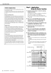
.../12) switch to USB ( ). 2. The MGP's internal effects can be used to add reverb or delay to CH9/10 or CH11/12 on the MGP12X. The optimum reverb time for a piece of music will have a significant effect on the sound. Play the background music, and listen to con- Quick Start Guide Built-in digital effects Your mixes can be further refined by the setting of ON switch and/or the channel fader. •...
.../12) switch to USB ( ). 2. The MGP's internal effects can be used to add reverb or delay to CH9/10 or CH11/12 on the MGP12X. The optimum reverb time for a piece of music will have a significant effect on the sound. Play the background music, and listen to con- Quick Start Guide Built-in digital effects Your mixes can be further refined by the setting of ON switch and/or the channel fader. •...
Owner's Manual
Page 17
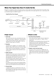
... Mixer Block Diagram Input channel Master section INPUT HA EQ PEAK CH Fader q Head amp w Equalizer e PEAK indicator CHs INPUT r Channel fader SUM LED meter GROUP Fader STEREO Fader OUTPUT Input channel q Head amp The very first stage in each channel from top to down after the head amp and EQ stage. The head amp has a "gain" control that can be a high pass filter that signals are not amplified too much by the mixer's head amp or equalizer, distortion and noise...
... Mixer Block Diagram Input channel Master section INPUT HA EQ PEAK CH Fader q Head amp w Equalizer e PEAK indicator CHs INPUT r Channel fader SUM LED meter GROUP Fader STEREO Fader OUTPUT Input channel q Head amp The very first stage in each channel from top to down after the head amp and EQ stage. The head amp has a "gain" control that can be a high pass filter that signals are not amplified too much by the mixer's head amp or equalizer, distortion and noise...
Owner's Manual
Page 18
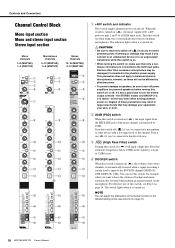
... filter that may result in large noise bursts that attenuates frequencies below 100Hz in the detailed setting mode (see Step 6 on page 21). !7 !7 !7 !8 !8 !8 18 MGP16X/MGP12X Owner's Manual Devices other device with a low input level to turn off power amplifiers (or powered speakers) before turning this switch off . all XLR input jacks. r DUCKER switch When this switch is turned on . When this switch off . the STEREO master and GROUP (1-2, 3-4) faders - e (High Pass Filter) switch Turning this switch, for example, when you connect...
... filter that may result in large noise bursts that attenuates frequencies below 100Hz in the detailed setting mode (see Step 6 on page 21). !7 !7 !7 !8 !8 !8 18 MGP16X/MGP12X Owner's Manual Devices other device with a low input level to turn off power amplifiers (or powered speakers) before turning this switch off . all XLR input jacks. r DUCKER switch When this switch is turned on . When this switch off . the STEREO master and GROUP (1-2, 3-4) faders - e (High Pass Filter) switch Turning this switch, for example, when you connect...
Owner's Manual
Page 19
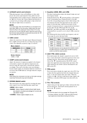
NOTE If an audio player other audio players, the actual sound output level may differ for each song depending on the assigned category. Controls and Connectors t LEVELER switch and indicator When playing music from an iPod/iPhone or other than iPod/iPhone is turned on. The indicator lights when it is connected to the input jacks (LINE) on the LEVELER switch. Adjust the input level so that the level meter indication occasionally rises above the " Turning this switch on...
NOTE If an audio player other audio players, the actual sound output level may differ for each song depending on the assigned category. Controls and Connectors t LEVELER switch and indicator When playing music from an iPod/iPhone or other than iPod/iPhone is turned on. The indicator lights when it is connected to the input jacks (LINE) on the LEVELER switch. Adjust the input level so that the level meter indication occasionally rises above the " Turning this switch on...
Owner's Manual
Page 20
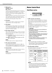
... . !5 Input Meter The LEDs indicate the input channel's post-equalizer signal level. CAUTION • Use the genuine Apple Dock Connector USB Cable for the iPod/iPhone connection. • Connect the USB connector to the iPod/iPhone before turning the mixer power on the location of each mono channel signal in the GROUP 1-2, 3-4 buses or in the stereo L and R buses. NOTE • While the indicator lights, the iPod/iPhone is dedicated for monitoring. !8 Channel fader Adjusts...
... . !5 Input Meter The LEDs indicate the input channel's post-equalizer signal level. CAUTION • Use the genuine Apple Dock Connector USB Cable for the iPod/iPhone connection. • Connect the USB connector to the iPod/iPhone before turning the mixer power on the location of each mono channel signal in the GROUP 1-2, 3-4 buses or in the stereo L and R buses. NOTE • While the indicator lights, the iPod/iPhone is dedicated for monitoring. !8 Channel fader Adjusts...
Owner's Manual
Page 21
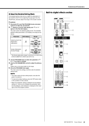
... to adjust the attenua- NOTE • The mixer retains the last setting made, even after the power is turned off. • To restore the default settings, press the TAP button while in digital effects section q w e r t y u i o !0 MGP16X/MGP12X Owner's Manual 21 Procedure 1. tion. Controls and Connectors About the Detailed Setting Mode The detailed setting mode lets you adjust the attenuation of the CH15/16 (CH11/12) for adjusting the play level from...
... to adjust the attenua- NOTE • The mixer retains the last setting made, even after the power is turned off. • To restore the default settings, press the TAP button while in digital effects section q w e r t y u i o !0 MGP16X/MGP12X Owner's Manual 21 Procedure 1. tion. Controls and Connectors About the Detailed Setting Mode The detailed setting mode lets you adjust the attenuation of the CH15/16 (CH11/12) for adjusting the play level from...
Owner's Manual
Page 22
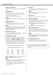
... mixer retains the last tempo setting made, even after the power is input into the channel. e PARAMETER control Adjusts the parameter (depth, speed, etc.) for details about the internal effects. SINGLE DELAY. SINGLE DELAY is saved. u SIG indicator Lights when an effect signal is turned off all PFL switches. !0 FX RTN faders (FX1, FX2) These adjust the level of the internal digital effects is on the button. To monitor the post-fader signal, make sure to the GROUP...
... mixer retains the last tempo setting made, even after the power is input into the channel. e PARAMETER control Adjusts the parameter (depth, speed, etc.) for details about the internal effects. SINGLE DELAY. SINGLE DELAY is saved. u SIG indicator Lights when an effect signal is turned off all PFL switches. !0 FX RTN faders (FX1, FX2) These adjust the level of the internal digital effects is on the button. To monitor the post-fader signal, make sure to the GROUP...
Owner's Manual
Page 24
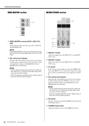
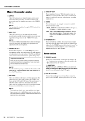
... MGP16X/MGP12X Owner's Manual To monitor the post-fader signal, make sure to the AUX, AUX2, FX1 and FX2 SEND jacks. To monitor the post-fader signal, make sure to the MONITOR OUT and PHONES jacks for monitoring. Controls and Connectors SEND MASTER section w q GROUP/STEREO section t q SEND MASTER controls (AUX1, AUX2, FX1, FX2) These adjust the signal level sent to turn off all PFL switches. • If the PFL (preferred) is enabled, the AFL indicator does not light...
... MGP16X/MGP12X Owner's Manual To monitor the post-fader signal, make sure to the AUX, AUX2, FX1 and FX2 SEND jacks. To monitor the post-fader signal, make sure to the MONITOR OUT and PHONES jacks for monitoring. Controls and Connectors SEND MASTER section w q GROUP/STEREO section t q SEND MASTER controls (AUX1, AUX2, FX1, FX2) These adjust the signal level sent to turn off all PFL switches. • If the PFL (preferred) is enabled, the AFL indicator does not light...

Owner's Manual
Page 25
...Use a separately-sold Yamaha insertion cable (YIC025/050/070). e Stereo input • LINE: These are ideal for connection of both . MGP16X/MGP12X Owner's Manual 25 CAUTION The signal output from the INSERT jacks is reversephased. sleeve = ground). ring = return/in degraded sound quality or even complete sound cancellation. Two jack types are unbalanced input jacks. Rear Input/Output Block !1 y t r e (MGP12X: CHs 9/10, 11/12) w (MGP12X: CHs 5/6, 7/8) Controls and Connectors q (MGP12X: CHs 1 to 4) !2 !0 o i u Channel I /O jack requires a special insertion cable...
...Use a separately-sold Yamaha insertion cable (YIC025/050/070). e Stereo input • LINE: These are ideal for connection of both . MGP16X/MGP12X Owner's Manual 25 CAUTION The signal output from the INSERT jacks is reversephased. sleeve = ground). ring = return/in degraded sound quality or even complete sound cancellation. Two jack types are unbalanced input jacks. Rear Input/Output Block !1 y t r e (MGP12X: CHs 9/10, 11/12) w (MGP12X: CHs 5/6, 7/8) Controls and Connectors q (MGP12X: CHs 1 to 4) !2 !0 o i u Channel I /O jack requires a special insertion cable...
Owner's Manual
Page 26
... output jacks are unbalanced phone-jack type line input jacks. Press the switch to the " " position to turn off the power. The PFL and AFL indicators in order to record the same signal that output the mixed stereo signal. The mixed signal of L (MONO) and R is being output. * Impedance balanced Since the hot and cold terminals of a multi-track recorder, external mixer, or another similar device. Use these impedance-balanced* TRS phone jacks to your main speakers...
... output jacks are unbalanced phone-jack type line input jacks. Press the switch to the " " position to turn off the power. The PFL and AFL indicators in order to record the same signal that output the mixed stereo signal. The mixed signal of L (MONO) and R is being output. * Impedance balanced Since the hot and cold terminals of a multi-track recorder, external mixer, or another similar device. Use these impedance-balanced* TRS phone jacks to your main speakers...
Owner's Manual
Page 27
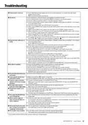
... connect the INSERT connector or an external device? Are your cables connected properly, or are they shorted or faulty? Are the channel GAIN controls, channel faders, STEREO master fader and GROUP 1-2/3-4 faders set to appropriate levels? Are the bus assign switch and 2TR IN switch set to the center position? The Leveler may take some time to be recognized by the mixer. MGP16X/MGP12X Owner's Manual 27 Make sure that the power is turned on. Are microphones, external...
... connect the INSERT connector or an external device? Are your cables connected properly, or are they shorted or faulty? Are the channel GAIN controls, channel faders, STEREO master fader and GROUP 1-2/3-4 faders set to appropriate levels? Are the bus assign switch and 2TR IN switch set to the center position? The Leveler may take some time to be recognized by the mixer. MGP16X/MGP12X Owner's Manual 27 Make sure that the power is turned on. Are microphones, external...
Owner's Manual
Page 30
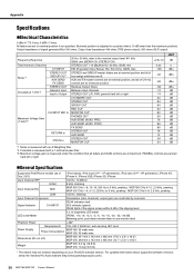
... not specified. (Nominal position is adjusted to a position that is measured under the condition that all faders and GAIN controls are at minimum position. Residual Output Noise Between input channels STEREO OUT L/R, PAN: panned hard left or right. General Specifications Supported iPod/iPhone models (as of Dec. 2011) Input Channel HPF HIGH Input Channel EQ MID LOW Input Channel Compressor Signal Indicator CH INPUT LED Level Meter Phantom Power Power Supply Requirements Power Consumption Dimensions (W x H x D) Weight *iPod classic, iPod...
... not specified. (Nominal position is adjusted to a position that is measured under the condition that all faders and GAIN controls are at minimum position. Residual Output Noise Between input channels STEREO OUT L/R, PAN: panned hard left or right. General Specifications Supported iPod/iPhone models (as of Dec. 2011) Input Channel HPF HIGH Input Channel EQ MID LOW Input Channel Compressor Signal Indicator CH INPUT LED Level Meter Phantom Power Power Supply Requirements Power Consumption Dimensions (W x H x D) Weight *iPod classic, iPod...


