Owner's Manual
Page 3
... switch, disconnect the electric plug from the outlet, and have it . (5)-4 1/2 MG206C/MG166CX/MG166C Owner's Manual 3 Even when the power switch is turned off the power switch, disconnect the ...overheating, possibly causing damage to the device(s), or even fire. • Avoid setting all equalizer controls and faders to their maximum. The required voltage is to be malfunctioning, ...the cord can result in a safe place for the device. Pulling by qualified Yamaha service personnel. PRECAUTIONS PLEASE READ CAREFULLY BEFORE PROCEEDING * Please keep an adequate gap between the...
... switch, disconnect the electric plug from the outlet, and have it . (5)-4 1/2 MG206C/MG166CX/MG166C Owner's Manual 3 Even when the power switch is turned off the power switch, disconnect the ...overheating, possibly causing damage to the device(s), or even fire. • Avoid setting all equalizer controls and faders to their maximum. The required voltage is to be malfunctioning, ...the cord can result in a safe place for the device. Pulling by qualified Yamaha service personnel. PRECAUTIONS PLEASE READ CAREFULLY BEFORE PROCEEDING * Please keep an adequate gap between the...
Owner's Manual
Page 4
...off for damage caused by copyright law. This is not in the ears, consult a physician. • Do not rest your Yamaha dealer. (5)-4 2/2 4 MG206C/MG166CX/MG166C Owner's Manual Handling caution • When turning on the AC power in your fingers or hands in the "STANDBY" ...position, electricity is on or off , the power amplifier should be held responsible for all devices, set all copyrights, and consult ...
...off for damage caused by copyright law. This is not in the ears, consult a physician. • Do not rest your Yamaha dealer. (5)-4 2/2 4 MG206C/MG166CX/MG166C Owner's Manual Handling caution • When turning on the AC power in your fingers or hands in the "STANDBY" ...position, electricity is on or off , the power amplifier should be held responsible for all devices, set all copyrights, and consult ...
Owner's Manual
Page 7
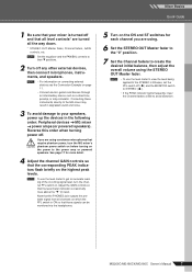
CAUTION If you are turned all the way down. * STEREO OUT Master fader, Channel faders, GAIN controls, etc. MG206C/MG166CX/MG166C Owner's Manual 7 Reverse this order when turning power off ( ) and the MONITOR switch to STEREO ( ). • If the PEAK indicator lights frequently, lower... create the desired initial balance, then adjust the overall volume using condenser microphones that require phantom power, turn the channel PFL switch on. NOTE Set the equalizer and the PAN/BAL controls to the MG mixer may result in the following order: Peripheral devices → MG mixer → ...
CAUTION If you are turned all the way down. * STEREO OUT Master fader, Channel faders, GAIN controls, etc. MG206C/MG166CX/MG166C Owner's Manual 7 Reverse this order when turning power off ( ) and the MONITOR switch to STEREO ( ). • If the PEAK indicator lights frequently, lower... create the desired initial balance, then adjust the overall volume using condenser microphones that require phantom power, turn the channel PFL switch on. NOTE Set the equalizer and the PAN/BAL controls to the MG mixer may result in the following order: Peripheral devices → MG mixer → ...
Owner's Manual
Page 10
... will depend on the music's tempo and density, but as reverb or delay. In addition to achieve the desired sound. Chorus is set properly to the phasing effect described above, the delay modulation causes a perceived pitch shift which, when mixed with no excessive peaks or distortion...compression you into the mix until you want without detracting from the clarity of the mix. OUTPUT (Min) (Max) INPUT 10 MG206C/MG166CX/MG166C Owner's Manual For phasing effects the shift is controlled, or "modulated", by an LFO, and recombined with the direct signal. With the ...
... will depend on the music's tempo and density, but as reverb or delay. In addition to achieve the desired sound. Chorus is set properly to the phasing effect described above, the delay modulation causes a perceived pitch shift which, when mixed with no excessive peaks or distortion...compression you into the mix until you want without detracting from the clarity of the mix. OUTPUT (Min) (Max) INPUT 10 MG206C/MG166CX/MG166C Owner's Manual For phasing effects the shift is controlled, or "modulated", by an LFO, and recombined with the direct signal. With the ...
Owner's Manual
Page 13
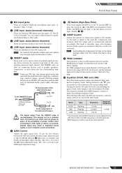
... jacks. The HPF cuts frequencies below clipping. 0 Equalizer (HIGH, MID and LOW) This three-band equalizer adjusts the channel's high, mid, and low frequency bands. Setting the knob to these levels reaches 3 dB below 80 Hz (the HPF does not apply to the line inputs of stereo input channels 3, 4). 8 COMP Control... automatically adjusted accordingly. This should not be a problem when connecting to an effect unit, but please be used to other types of device. MG206C/MG166CX/MG166C Owner's Manual 13 sleeve = ground).
... jacks. The HPF cuts frequencies below clipping. 0 Equalizer (HIGH, MID and LOW) This three-band equalizer adjusts the channel's high, mid, and low frequency bands. Setting the knob to these levels reaches 3 dB below 80 Hz (the HPF does not apply to the line inputs of stereo input channels 3, 4). 8 COMP Control... automatically adjusted accordingly. This should not be a problem when connecting to an effect unit, but please be used to other types of device. MG206C/MG166CX/MG166C Owner's Manual 13 sleeve = ground).
Owner's Manual
Page 14
... adjust the balance between left and right channels. Use these faders to the GROUP 3/4 bus turn the ON switch on ( ). These knobs should generally be set close to the STEREO L/R bus. If the switch is received via the MIC jack or L (MONO) input only, and as follows: • MG206C ... B) AUX4: Post-fader • MG166CX AUX1: Pre-fader AUX2: Pre-fader/post-fader (determined by the AUX PRE switch B) EFFECT: Post-fader • MG166C AUX1: Pre-fader AUX2: Pre-fader/post-fader (determines by the channel fader I Channel Fader Adjusts the level of the channel signal. C PAN Control PAN...
... adjust the balance between left and right channels. Use these faders to the GROUP 3/4 bus turn the ON switch on ( ). These knobs should generally be set close to the STEREO L/R bus. If the switch is received via the MIC jack or L (MONO) input only, and as follows: • MG206C ... B) AUX4: Post-fader • MG166CX AUX1: Pre-fader AUX2: Pre-fader/post-fader (determined by the AUX PRE switch B) EFFECT: Post-fader • MG166C AUX1: Pre-fader AUX2: Pre-fader/post-fader (determines by the channel fader I Channel Fader Adjusts the level of the channel signal. C PAN Control PAN...
Owner's Manual
Page 17
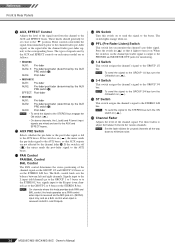
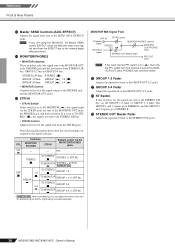
... for example, to connect to turn all output controls (STEREO OUT Master fader, GROUP 1-2 fader, GROUP 3-4 fader, etc.) to their minimum settings before turning this switch on the signal output via the STEREO OUT jacks. Turn this switch on the mixer supplies DC +48 V power to ...MONITOR OUT jacks. 9 PHANTOM +48 V Switch This switch toggles phantom power on the mixer supplies +48V phantom power to the mixer. MG206C/MG166CX/MG166C Owner's Manual 17 Reference Front & Rear Panels 1 SEND Jacks (AUX, EFFECT) These impedance balanced* TRS phone jacks output the signals from an ...
... for example, to connect to turn all output controls (STEREO OUT Master fader, GROUP 1-2 fader, GROUP 3-4 fader, etc.) to their minimum settings before turning this switch on the signal output via the STEREO OUT jacks. Turn this switch on the mixer supplies DC +48 V power to ...MONITOR OUT jacks. 9 PHANTOM +48 V Switch This switch toggles phantom power on the mixer supplies +48V phantom power to the mixer. MG206C/MG166CX/MG166C Owner's Manual 17 Reference Front & Rear Panels 1 SEND Jacks (AUX, EFFECT) These impedance balanced* TRS phone jacks output the signals from an ...
Owner's Manual
Page 18
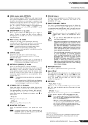
...MONITOR OUT jacks, PHONES jack, and level meter. H ST Switch If this switch is on ( ), then only the PFL output from that channel is set to TO MONITOR ( ), the signals input via the MONITOR/PHONES jacks PFL STEREO TO STEREO STEREO (+ 2TR IN) TO MONITOR STEREO + 2TR IN *...3/4 bus. The GROUP 1 and 3 signals go to STEREO L and the GROUP 2 and 4 signals go to the STEREO OUT jacks. 18 MG206C/MG166CX/MG166C Owner's Manual The following illustration shows how the switch settings correspond to the GROUP OUT 3/ 4 jacks. G GROUP 3-4 Fader Adjust the signal level to the signal selection.
...MONITOR OUT jacks, PHONES jack, and level meter. H ST Switch If this switch is on ( ), then only the PFL output from that channel is set to TO MONITOR ( ), the signals input via the MONITOR/PHONES jacks PFL STEREO TO STEREO STEREO (+ 2TR IN) TO MONITOR STEREO + 2TR IN *...3/4 bus. The GROUP 1 and 3 signals go to STEREO L and the GROUP 2 and 4 signals go to the STEREO OUT jacks. 18 MG206C/MG166CX/MG166C Owner's Manual The following illustration shows how the switch settings correspond to the GROUP OUT 3/ 4 jacks. G GROUP 3-4 Fader Adjust the signal level to the signal selection.
Owner's Manual
Page 20
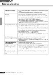
... the AUX 1, 2 or 3 jack (MG206C), or to the AUX1 or 2 jack (MG166CX/MG166C) and turn the PRE switch on each channel on each channel. ❑ Is the input signal from the connected device set to appropriate levels? ❑ Are two different instruments connected to the XLR-type and phone... appropriate levels? ❑ Are the MONITOR switch and 2TR IN switch set properly? ❑ Are your speaker cables connected properly, or are they shorted? ❑ If the above checks do not identify the problem, call Yamaha for a list of the channels you are not using condenser microphones, is the ...
... the AUX 1, 2 or 3 jack (MG206C), or to the AUX1 or 2 jack (MG166CX/MG166C) and turn the PRE switch on each channel on each channel. ❑ Is the input signal from the connected device set to appropriate levels? ❑ Are two different instruments connected to the XLR-type and phone... appropriate levels? ❑ Are the MONITOR switch and 2TR IN switch set properly? ❑ Are your speaker cables connected properly, or are they shorted? ❑ If the above checks do not identify the problem, call Yamaha for a list of the channels you are not using condenser microphones, is the ...
Owner's Manual
Page 22
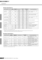
... * Sensitivity : The lowest level that will produce an output of +4 dB (1.23 V), or the nominal output level when the unit is set to the maximum level. (All faders and level controls are at their maximum position.) ■ Output Specifications Output Connectors Output Impedance ...Sleeve = GND]) RCA pin jack TRS phone jack (impedance balanced [Tip = HOT, Ring = COLD, Sleeve = GND]) TRS phone jack 76 MG206C/MG166CX/MG166C Owner's Manual Reference Specifications ■ Input Specifications Input Connectors CH INPUT MIC (CHs 1-12) CH INPUT LINE (CHs 1-12) ST CH MIC...
... * Sensitivity : The lowest level that will produce an output of +4 dB (1.23 V), or the nominal output level when the unit is set to the maximum level. (All faders and level controls are at their maximum position.) ■ Output Specifications Output Connectors Output Impedance ...Sleeve = GND]) RCA pin jack TRS phone jack (impedance balanced [Tip = HOT, Ring = COLD, Sleeve = GND]) TRS phone jack 76 MG206C/MG166CX/MG166C Owner's Manual Reference Specifications ■ Input Specifications Input Connectors CH INPUT MIC (CHs 1-12) CH INPUT LINE (CHs 1-12) ST CH MIC...
Owner's Manual
Page 24
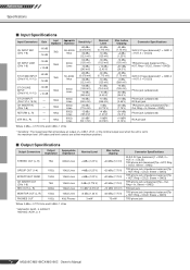
...Sensitivity : The lowest level that will produce an output of +4 dB (1.23 V), or the nominal output level when the unit is set to the maximum level. (All faders and level controls are at their maximum position.) ■ Output Specifications Output Connectors Output ...; Lines MONITOR OUT (L, R) PHONES OUT 150Ω 100Ω 10kΩ Lines 40Ω Phones Where 0 dBu = 0.775 Vrms and 0 dBV= 1 Vrms * MG166CX: AUX1, 2, EFFECT MG166C: AUX1, 2, 3 Nominal Level +4dBu (1.23 V) +4dBu (1.23 V) +4dBu (1.23 V) 0 dBu (0.775 V) -10 dBV (0.316 V) +4 dBu (1.23 V) 3 mW Max. RETURN (L, R) ...
...Sensitivity : The lowest level that will produce an output of +4 dB (1.23 V), or the nominal output level when the unit is set to the maximum level. (All faders and level controls are at their maximum position.) ■ Output Specifications Output Connectors Output ...; Lines MONITOR OUT (L, R) PHONES OUT 150Ω 100Ω 10kΩ Lines 40Ω Phones Where 0 dBu = 0.775 Vrms and 0 dBV= 1 Vrms * MG166CX: AUX1, 2, EFFECT MG166C: AUX1, 2, 3 Nominal Level +4dBu (1.23 V) +4dBu (1.23 V) +4dBu (1.23 V) 0 dBu (0.775 V) -10 dBV (0.316 V) +4 dBu (1.23 V) 3 mW Max. RETURN (L, R) ...


