
Owner's Manual
Page 2
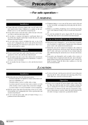
... power cord. A damaged power cord is a fire and electrical shock hazard. Using the unit with all connecting cables. Damaged cables may be damaged, turn it from the AC outlet, and remove all the windows closed, or places that receive direct sunlight. - Use only in this unit for a replacement. Leaving it is still connected. If you will not use this Owner's Manual or as smoke, odor, or noise...
... power cord. A damaged power cord is a fire and electrical shock hazard. Using the unit with all connecting cables. Damaged cables may be damaged, turn it from the AC outlet, and remove all the windows closed, or places that receive direct sunlight. - Use only in this unit for a replacement. Leaving it is still connected. If you will not use this Owner's Manual or as smoke, odor, or noise...
Owner's Manual
Page 3
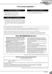
... by Yamaha-Kemble Music (U.K.) Ltd. (2 wires). Failure to follow instructions could void your plug proceed as switches, rotary controls, faders, and connectors-deteriorates over time. NOTE: This product has been tested and found to use . If this product is 300 ohm ribbon lead, change the lead-in FCC Regulations, Part 15 for a long time, make sure you unplug the AC power adaptor from...
... by Yamaha-Kemble Music (U.K.) Ltd. (2 wires). Failure to follow instructions could void your plug proceed as switches, rotary controls, faders, and connectors-deteriorates over time. NOTE: This product has been tested and found to use . If this product is 300 ohm ribbon lead, change the lead-in FCC Regulations, Part 15 for a long time, make sure you unplug the AC power adaptor from...
Owner's Manual
Page 4
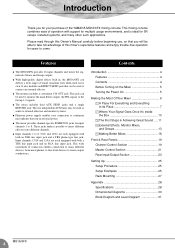
... on external power. This jack can deliver a wide range of the YAMAHA MG16/6FX mixing console. G With high-quality digital effects built in Achieving Great Sound .... 11 4 External Effects, Monitor Mixes, and Groups 13 5 Making Better Mixes 16 Front & Rear Panels 19 Channel Control Section 19 Master Control Section 21 Rear Input/Output Section 23 Setting Up 25 Setup Procedure 25 Setup Examples 25 Rack Mounting 27 Appendix 28 Specifications 28 Dimensional Diagrams 30 Block Diagram and Level Diagram 31 4 MG16/6FX Input channels 13...
... on external power. This jack can deliver a wide range of the YAMAHA MG16/6FX mixing console. G With high-quality digital effects built in Achieving Great Sound .... 11 4 External Effects, Monitor Mixes, and Groups 13 5 Making Better Mixes 16 Front & Rear Panels 19 Channel Control Section 19 Master Control Section 21 Rear Input/Output Section 23 Setting Up 25 Setup Procedure 25 Setup Examples 25 Rack Mounting 27 Appendix 28 Specifications 28 Dimensional Diagrams 30 Block Diagram and Level Diagram 31 4 MG16/6FX Input channels 13...

Owner's Manual
Page 7
... connector when connecting a CD player or other home audio type source to as a "TRS" phone jack. The connector's label will the owner's manual (you do the inputs and outputs of signal it 's too easily confusable with no problem. Microphone cables usually have this type of connector, as will usually tell you ?). Questions you can't always tell what type of most commonly used on...
... connector when connecting a CD player or other home audio type source to as a "TRS" phone jack. The connector's label will the owner's manual (you do the inputs and outputs of signal it 's too easily confusable with no problem. Microphone cables usually have this type of connector, as will usually tell you ?). Questions you can't always tell what type of most commonly used on...
Owner's Manual
Page 9
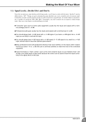
... on the inputs and/or outputs that feature a "Gain" control-such as the mono-channel inputs on your Yamaha mixer-will result in mind: G "Consumer" gear (such as electronic signal levels. Making the Most Of Your Mixer 1-3. Things can be an expert to make matters worse there are likely to match the level of +4 dB. G Professional audio gear usually has line inputs and outputs with a +4 dB signal. G You...
... on the inputs and/or outputs that feature a "Gain" control-such as the mono-channel inputs on your Yamaha mixer-will result in mind: G "Consumer" gear (such as electronic signal levels. Making the Most Of Your Mixer 1-3. Things can be an expert to make matters worse there are likely to match the level of +4 dB. G Professional audio gear usually has line inputs and outputs with a +4 dB signal. G You...

Owner's Manual
Page 10
... large signals are "summed" (mixed) together here. 5 Master Fader & Level Meter A stereo, mono, or bus master fader and the mixer's main output level meter. Here's a greatly simplified block diagram of a generic mixer to cut than boost. 10 MG16/6FX 3 Channel Peak LED & Fader The channel peak LED is applied the EQ stage also has gain. You can look like a space-station schematic. Small signals (e.g. i.e. Greatly Simplified Mixer Block Diagram Input Channel Master Section Signals from all of the mixer's input channels are...
... large signals are "summed" (mixed) together here. 5 Master Fader & Level Meter A stereo, mono, or bus master fader and the mixer's main output level meter. Here's a greatly simplified block diagram of a generic mixer to cut than boost. 10 MG16/6FX 3 Channel Peak LED & Fader The channel peak LED is applied the EQ stage also has gain. You can look like a space-station schematic. Small signals (e.g. i.e. Greatly Simplified Mixer Block Diagram Input Channel Master Section Signals from all of the mixer's input channels are...
Owner's Manual
Page 11
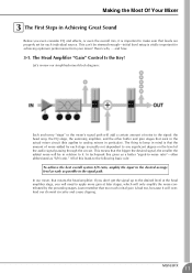
... The Head Amplifier "Gain" Control Is the Key! In tech-speak this gives us a better "signal-to-noise ratio"-often abbreviated as possible in the signal path. Just remember that the amount of the audio signal passing through the circuit. Let's review our simplified mixer block diagram: Each and every "stage" in the mixer's signal path will add a certain amount...
... The Head Amplifier "Gain" Control Is the Key! In tech-speak this gives us a better "signal-to-noise ratio"-often abbreviated as possible in the signal path. Just remember that the amount of the audio signal passing through the circuit. Let's review our simplified mixer block diagram: Each and every "stage" in the mixer's signal path will add a certain amount...
Owner's Manual
Page 12
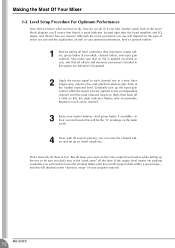
... mixer you take another quick look at the loudest expected level. Gradually turn up the mix to their nominal levels (this will be sure you use and the application, as well as your program material. 12 MG16/6FX That's basically all the time. and this will depend on the main output level meters while setting up the input gain control while the signal is to their minimum: master faders, group faders (if provided), channel faders...
... mixer you take another quick look at the loudest expected level. Gradually turn up the mix to their nominal levels (this will be sure you use and the application, as well as your program material. 12 MG16/6FX That's basically all the time. and this will depend on the main output level meters while setting up the input gain control while the signal is to their minimum: master faders, group faders (if provided), channel faders...
Owner's Manual
Page 13
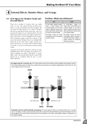
... main program. Post-fader sends are most commonly used in conjunction with the mixer's AUX or effect returns for example-and the output from the main mix, and 2) to provide monitor mixes. Larger mixing consoles can have 6, 8, or even more , can handle both the AUX send level control and the channel fader. AUX Send Level Channel Fader Master Fader AUX Send Level AUX Return Level Post-fader send for a monitor mix. pre post A "pre-fader" signal is used in this case. Using the AUX buses and level controls is fed to handle a variety of the main mix. Pre-fader...
... main program. Post-fader sends are most commonly used in conjunction with the mixer's AUX or effect returns for example-and the output from the main mix, and 2) to provide monitor mixes. Larger mixing consoles can have 6, 8, or even more , can handle both the AUX send level control and the channel fader. AUX Send Level Channel Fader Master Fader AUX Send Level AUX Return Level Post-fader send for a monitor mix. pre post A "pre-fader" signal is used in this case. Using the AUX buses and level controls is fed to handle a variety of the main mix. Pre-fader...

Owner's Manual
Page 14
... as quickly as possible. Once the mix between the channels assigned to the group is established via "Group" outputs, or it can send the group signal to the main program bus. If you can be mixed in with the main stereo program. Channel faders Assigned to Group (Controlled As a Group) Group Fader A group of channels that group is the way to be assigned to the main program (stereo) bus to go. Using Groups Group buses and faders can be adjusted all together while maintaining their relative levels, grouping is also assigned...
... as quickly as possible. Once the mix between the channels assigned to the group is established via "Group" outputs, or it can send the group signal to the main program bus. If you can be mixed in with the main stereo program. Channel faders Assigned to Group (Controlled As a Group) Group Fader A group of channels that group is the way to be assigned to the main program (stereo) bus to go. Using Groups Group buses and faders can be adjusted all together while maintaining their relative levels, grouping is also assigned...

Owner's Manual
Page 15
... AUX sends and returns, the channel insert only applies to the input of the external processor, and the other carries the "return" signal from the output of the external processor MG16/6FX 15 Channel inserts are almost always located before the channel fader and, when used with a special insert cable that has a TRS phone jack on one end and mono phone jacks on the split "Y" end. Channel Fader When a plug is inserted into the channel insert jack...
... AUX sends and returns, the channel insert only applies to the input of the external processor, and the other carries the "return" signal from the output of the external processor MG16/6FX 15 Channel inserts are almost always located before the channel fader and, when used with a special insert cable that has a TRS phone jack on one end and mono phone jacks on the split "Y" end. Channel Fader When a plug is inserted into the channel insert jack...
Owner's Manual
Page 16
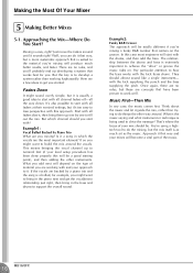
... drums to support the overall sound. What is the music saying and what instrument or technique is as the music. There are no rules, but it guide the mix, rather than working with and your mix should almost sound like a single instrument- In this will depend on the type of your approach to start with all channel faders off-all faders down . Once...
... drums to support the overall sound. What is the music saying and what instrument or technique is as the music. There are no rules, but it guide the mix, rather than working with and your mix should almost sound like a single instrument- In this will depend on the type of your approach to start with all channel faders off-all faders down . Once...

Owner's Manual
Page 20
... passes through the MIC jack or into the R input (even channel) feed to the Stereo L bus; The BAL control knob sets the balance between left and right channels. If you monitor the channel's pre-fader signal. To send the signal to the Stereo bus, set the switch on ( ), the mixer sends the pre-fader signal-the signal prior to passage though channel fader B-to the channel. A GROUP Switches Use these faders to the Group 1-2 and/or Group 3-4 buses. Use these switches to send the channel's signal to adjust the volume balance among...
... passes through the MIC jack or into the R input (even channel) feed to the Stereo L bus; The BAL control knob sets the balance between left and right channels. If you monitor the channel's pre-fader signal. To send the signal to the Stereo bus, set the switch on ( ), the mixer sends the pre-fader signal-the signal prior to passage though channel fader B-to the channel. A GROUP Switches Use these faders to the Group 1-2 and/or Group 3-4 buses. Use these switches to send the channel's signal to adjust the volume balance among...
Owner's Manual
Page 21
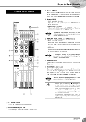
... that provide MIC input jacks (CHs 1-8, 9/10, 11/12). MG16/6FX 21 Set this switch off . Master Control Section C B 7 A D 0 5 4 6 9 3 8 2 1 1 ST Master Fader Adjusts the signal level to the ST OUT jacks. 2 GROUP Faders (1-2, 3-4) Adjust the signal level to the GROUP OUT 1 to the Stereo bus. NOTE These Master SEND controls do not affect the level of the signal sent from the internal digital effector onto the Master EFFECT bus. 5 RETURN (AUX1, AUX2, and ST Controls) • AUX1 and AUX2 Controls Adjust the level of the mixed L/R signal sent...
... that provide MIC input jacks (CHs 1-8, 9/10, 11/12). MG16/6FX 21 Set this switch off . Master Control Section C B 7 A D 0 5 4 6 9 3 8 2 1 1 ST Master Fader Adjusts the signal level to the ST OUT jacks. 2 GROUP Faders (1-2, 3-4) Adjust the signal level to the GROUP OUT 1 to the Stereo bus. NOTE These Master SEND controls do not affect the level of the signal sent from the internal digital effector onto the Master EFFECT bus. 5 RETURN (AUX1, AUX2, and ST Controls) • AUX1 and AUX2 Controls Adjust the level of the mixed L/R signal sent...

Owner's Manual
Page 22
... & Rear Panels 8 Level-Meter Signal Switches These level-meter switches, together with the channel PFL switches, select the signal that is sent through the C-R/PHONES control to be applied. Switch Signal PFL 1 2TR IN 2 ST-GROUP GROUP PFL ON 2TR - B ST GRAPHIC EQUALIZER This 7-band equalizer adjusts the sound of ±12 dB. NOTE The signal monitored by these jacks is sent to the C-R OUT jacks (as shown in 8 above (the level to the STEREO bus...
... & Rear Panels 8 Level-Meter Signal Switches These level-meter switches, together with the channel PFL switches, select the signal that is sent through the C-R/PHONES control to be applied. Switch Signal PFL 1 2TR IN 2 ST-GROUP GROUP PFL ON 2TR - B ST GRAPHIC EQUALIZER This 7-band equalizer adjusts the sound of ±12 dB. NOTE The signal monitored by these jacks is sent to the C-R OUT jacks (as shown in 8 above (the level to the STEREO bus...
Owner's Manual
Page 23
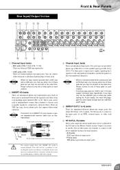
... 11/12 also support monaural input. NOTE Connection to an INSERT I/O jack requires a special separately-sold insertion cable such as graphic equalizers, compressors, and noise filters. Use these jacks is in the Master Control section. Please connect to only of these jacks to input stereo signals, inputting the L signal(s) to the odd-numbered channel(s) and the R signal(s) to the even-numbered channel(s). Two jack types are unbalanced phone-type input/output jacks. You use these jacks on each channel. • The...
... 11/12 also support monaural input. NOTE Connection to an INSERT I/O jack requires a special separately-sold insertion cable such as graphic equalizers, compressors, and noise filters. Use these jacks is in the Master Control section. Please connect to only of these jacks to input stereo signals, inputting the L signal(s) to the odd-numbered channel(s) and the R signal(s) to the even-numbered channel(s). Two jack types are unbalanced phone-type input/output jacks. You use these jacks on each channel. • The...

Owner's Manual
Page 24
... or DAT) directly to the mixer for a long while, be unbalanced. 24 MG16/6FX A POWER Switch Use this mixer. B AC ADAPTOR IN Connector Connects to ON or STANDBY. By connecting these jacks when you can adjust the signal level using the 2TR IN control in the STANDBY position. If you use the mixer again for monitoring. Connector Polarities MIC INPUT, ST OUT LINE INPUT (monaural channels), GROUP OUT, ST OUT, C-R OUT, AUX1, AUX2, EFFECT* INSERT I/O PHONES...
... or DAT) directly to the mixer for a long while, be unbalanced. 24 MG16/6FX A POWER Switch Use this mixer. B AC ADAPTOR IN Connector Connects to ON or STANDBY. By connecting these jacks when you can adjust the signal level using the 2TR IN control in the STANDBY position. If you use the mixer again for monitoring. Connector Polarities MIC INPUT, ST OUT LINE INPUT (monaural channels), GROUP OUT, ST OUT, C-R OUT, AUX1, AUX2, EFFECT* INSERT I/O PHONES...
Owner's Manual
Page 25
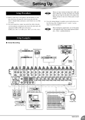
... time. Setup Examples I Home Recording Effector Rhythm Machine Effector Effector Synthesizer MTR Guitar Sound Source (CD, MD, DAT, cassette, video, etc.) Powered Monitor Speakers Master Recorder (MD, CD-R, DAT, etc.) Personal Computer MTR Microphone Headphones MG16/6FX 25 Also be sure that all of the mixer's channel faders and master control faders are set all devices are turned off the power in the following order: Peripheral devices → mixer → power amps (or powered speakers). Please connect...
... time. Setup Examples I Home Recording Effector Rhythm Machine Effector Effector Synthesizer MTR Guitar Sound Source (CD, MD, DAT, cassette, video, etc.) Powered Monitor Speakers Master Recorder (MD, CD-R, DAT, etc.) Personal Computer MTR Microphone Headphones MG16/6FX 25 Also be sure that all of the mixer's channel faders and master control faders are set all devices are turned off the power in the following order: Peripheral devices → mixer → power amps (or powered speakers). Please connect...

Owner's Manual
Page 28
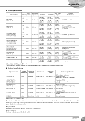
... S/N) ST, GROUP Master fader at maximum level) -128 dBu Equivalent input noise (CHs 1 to 15/16) 3 Graphic Equalizer Internal Digital Effects Monaural/Stereo Input Peak Indicator Level Meters Phantom +48 VDC Power (Balanced input) Included Accessory Power Supply Power Consumption Max. low pass filter (equivalent to 20 kHz, -∞ filter). (CH MIC INPUT to ST, GROUP OUT/AUX, EFFECT SEND) 2 Turning PAN/BAL to ST) 16 dB AUX RETURN → ST OUT 9 dB AUX RETURN → AUX SEND 27...
... S/N) ST, GROUP Master fader at maximum level) -128 dBu Equivalent input noise (CHs 1 to 15/16) 3 Graphic Equalizer Internal Digital Effects Monaural/Stereo Input Peak Indicator Level Meters Phantom +48 VDC Power (Balanced input) Included Accessory Power Supply Power Consumption Max. low pass filter (equivalent to 20 kHz, -∞ filter). (CH MIC INPUT to ST, GROUP OUT/AUX, EFFECT SEND) 2 Turning PAN/BAL to ST) 16 dB AUX RETURN → ST OUT 9 dB AUX RETURN → AUX SEND 27...
Owner's Manual
Page 29
...; line -26 dBV (50.1 mV) -10 dBV (316 mV) +10 dBV (3.16 V) RCA pin jack Where 0 dBu = 0.775 V and 0 dBV= 1 V * Input sensitivity: the lowest level that will produce the nominal output level when the unit is set to change or modify products or specifications at any time without prior notice. R: cold; reserves the right to maximum gain. European Models...
...; line -26 dBV (50.1 mV) -10 dBV (316 mV) +10 dBV (3.16 V) RCA pin jack Where 0 dBu = 0.775 V and 0 dBV= 1 V * Input sensitivity: the lowest level that will produce the nominal output level when the unit is set to change or modify products or specifications at any time without prior notice. R: cold; reserves the right to maximum gain. European Models...


