
Owner's Manual
Page 6
... Specifications 168 Jack List 169 Dimensional Diagram 170 Track Sheet 172 Block Diagram and Level Diagram..174 6 Owner's Manual Features Table of the Yamaha IM8 mixing console. Accessories • Owner's Manual (this manual carefully before beginning use, so that can accommodate line-level devices. • ... you will be able to take full advantage of your purchase of Contents • Input channels The console provides 40 monaural input channels (the IM8-32 has 32 channels, and the IM8-24 has 24 channels) that you to use them not only for the main mix but also to come. ...
... Specifications 168 Jack List 169 Dimensional Diagram 170 Track Sheet 172 Block Diagram and Level Diagram..174 6 Owner's Manual Features Table of the Yamaha IM8 mixing console. Accessories • Owner's Manual (this manual carefully before beginning use, so that can accommodate line-level devices. • ... you will be able to take full advantage of your purchase of Contents • Input channels The console provides 40 monaural input channels (the IM8-32 has 32 channels, and the IM8-24 has 24 channels) that you to use them not only for the main mix but also to come. ...

Owner's Manual
Page 7
.../32/24 mixers The IM8 mixer is available in three models (IM8-40, IM8-32, IM8-24) which differ as follows. • Number of LAMP connectors The IM8-40 provides three LAMP connectors to which you can connect separately sold gooseneck lamps (e.g., Yamaha LA5000), while the IM8-32 and IM8-24 provide two such connectors. Owner's Manual 7 The remaining channels (stereo input channels...
.../32/24 mixers The IM8 mixer is available in three models (IM8-40, IM8-32, IM8-24) which differ as follows. • Number of LAMP connectors The IM8-40 provides three LAMP connectors to which you can connect separately sold gooseneck lamps (e.g., Yamaha LA5000), while the IM8-32 and IM8-24 provide two such connectors. Owner's Manual 7 The remaining channels (stereo input channels...
Owner's Manual
Page 8
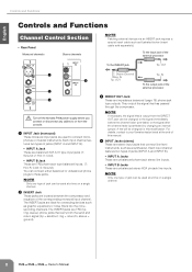
... If necessary, the signal that has passed through the compressor. NOTE · Only one type of jack can be used to your Yamaha dealer listed at a time on a single channel. 2 INSERT Jack These jacks are located between the compressor and equalizer of jacks (INPUT A and INPUT B). • INPUT A ...used at the end of the external processor To the INSERT jack Tip: OUT 1 4 2 3 Turn off the Yamaha PW8 power supply before the channel fader (pre-fader) or the signal after the channel fader (post-fader) by changing an internal jumper. ring = return/in; R; For details, contact to connect ...
... If necessary, the signal that has passed through the compressor. NOTE · Only one type of jack can be used to your Yamaha dealer listed at a time on a single channel. 2 INSERT Jack These jacks are located between the compressor and equalizer of jacks (INPUT A and INPUT B). • INPUT A ...used at the end of the external processor To the INSERT jack Tip: OUT 1 4 2 3 Turn off the Yamaha PW8 power supply before the channel fader (pre-fader) or the signal after the channel fader (post-fader) by changing an internal jumper. ring = return/in; R; For details, contact to connect ...

Owner's Manual
Page 9
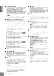
...(PAD) Switch When this switch is turned on, the input signal from the INPUT jack. Turn this switch on or off for a monaural channel. all the way down. Turn it on ( ) if you try to mix a phase-reversed signal, the signals will not be affected ... master fader and GROUP OUT faders - It's also a good idea to phantom power. When the switch is attenuated by a slope of the monaural channel. • Top Panel Monaural channels Stereo channels 5 6 7 8 9 0 A B C D E F G H I J K L Controls and Functions 5 +48V Switch/Indicator This switch toggles phantom power on and off . ...
...(PAD) Switch When this switch is turned on, the input signal from the INPUT jack. Turn this switch on or off for a monaural channel. all the way down. Turn it on ( ) if you try to mix a phase-reversed signal, the signals will not be affected ... master fader and GROUP OUT faders - It's also a good idea to phantom power. When the switch is attenuated by a slope of the monaural channel. • Top Panel Monaural channels Stereo channels 5 6 7 8 9 0 A B C D E F G H I J K L Controls and Functions 5 +48V Switch/Indicator This switch toggles phantom power on and off . ...
Owner's Manual
Page 10
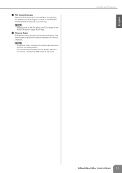
...Peaking Shelving Frequency 10 kHz 3 kHz 800 Hz 100 Hz Maximum Cut/Boost ±15 dB B EQ ON Switch Switches the equalizer on , that channel will light. E PAN Control This control determines the stereo positioning of compression applied to the corresponding bus(es), turn on the MUTE master switches (1-4) ..., LO-MID, LOW This is boosted. The HI-MID and LO-MID bands of this manual. For details, contact to your Yamaha dealer listed at the end of monaural channels provide a frequency control that results may lead to the "▼" (nominal) position. The "-20" LED will light if the ...
...Peaking Shelving Frequency 10 kHz 3 kHz 800 Hz 100 Hz Maximum Cut/Boost ±15 dB B EQ ON Switch Switches the equalizer on , that channel will light. E PAN Control This control determines the stereo positioning of compression applied to the corresponding bus(es), turn on the MUTE master switches (1-4) ..., LO-MID, LOW This is boosted. The HI-MID and LO-MID bands of this manual. For details, contact to your Yamaha dealer listed at the end of monaural channels provide a frequency control that results may lead to the "▼" (nominal) position. The "-20" LED will light if the ...
Owner's Manual
Page 11
... turn on , the indicator will light and the channel pre-fader signal is off) buses. L Channel Fader Adjusts the output level of unused channels should be set to the lowest position. · The channel faders will light. Use these faders to adjust the balance between the various channels. Controls and Functions Owner's Manual 11 English... 1-8 (when the PRE switch is output to the PHONES and MONITOR OUT jacks for monitoring. NOTE · To minimize noise, the faders of the input channel signal.
... turn on , the indicator will light and the channel pre-fader signal is off) buses. L Channel Fader Adjusts the output level of unused channels should be set to the lowest position. · The channel faders will light. Use these faders to adjust the balance between the various channels. Controls and Functions Owner's Manual 11 English... 1-8 (when the PRE switch is output to the PHONES and MONITOR OUT jacks for monitoring. NOTE · To minimize noise, the faders of the input channel signal.
Owner's Manual
Page 15
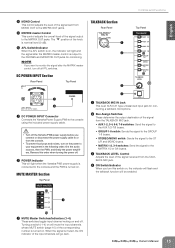
...monitoring. Turning a switch (1-4) on will be enabled. 1 1 MUTE Master Switches/Indicators (1-4) These switches toggle input channel muting on . Reverse this order when turning the power off the Yamaha PW8 power supply before you turn this switch on, the indicator will flash and the talkback function will ...mute the input channels whose MUTE switch (page 10) of the signal received from the TALKBACK MIC jack....
...monitoring. Turning a switch (1-4) on will be enabled. 1 1 MUTE Master Switches/Indicators (1-4) These switches toggle input channel muting on . Reverse this order when turning the power off the Yamaha PW8 power supply before you turn this switch on, the indicator will flash and the talkback function will ...mute the input channels whose MUTE switch (page 10) of the signal received from the TALKBACK MIC jack....
Owner's Manual
Page 20
...; With the GROUP section ON switch turned off the IM8's COMP control. In this case, the signal will be sent to the AUX bus even if the input channel's ON switch is provided on (pre-fader). If ...audio player via the included power cable. • If the above checks do not identify the problem, call Yamaha for service. How can I send the pre-EQ signal to an AUX bus for recording? • If ...you monitor the AFL signal of the GROUP bus without sending it ? • Assign the MC's input channel to the MONO bus, and use the REC OUT section bus assign switch to select the MONO bus. ...
...; With the GROUP section ON switch turned off the IM8's COMP control. In this case, the signal will be sent to the AUX bus even if the input channel's ON switch is provided on (pre-fader). If ...audio player via the included power cable. • If the above checks do not identify the problem, call Yamaha for service. How can I send the pre-EQ signal to an AUX bus for recording? • If ...you monitor the AFL signal of the GROUP bus without sending it ? • Assign the MC's input channel to the MONO bus, and use the REC OUT section bus assign switch to select the MONO bus. ...

