
Owner's Manual
Page 2
... interference harmful to products distributed by YAMAHA CORPORATION OF AMERICA. (FCC DoC) If the antenna lead-in to use the product. 2. See user manual instructions if interference to radio reception is 300 ohm ribbon lead, change the lead-in is suspected. * This applies only to the operation of the FCC Rules. Cable/s supplied with Part 15 of other electronic devices...
... interference harmful to products distributed by YAMAHA CORPORATION OF AMERICA. (FCC DoC) If the antenna lead-in to use the product. 2. See user manual instructions if interference to radio reception is 300 ohm ribbon lead, change the lead-in is suspected. * This applies only to the operation of the FCC Rules. Cable/s supplied with Part 15 of other electronic devices...
Owner's Manual
Page 3
... an equilateral triangle is intended to alert the user to the presence of important operating and maintenance (servicing) instructions in accordance with the manufacturer's instructions. 8 Do not install near any heat sources such as power-supply cord or plug is damaged, liquid has been spilled or objects have fallen into your safety. Install in the literature accompanying the product. When a cart...
... an equilateral triangle is intended to alert the user to the presence of important operating and maintenance (servicing) instructions in accordance with the manufacturer's instructions. 8 Do not install near any heat sources such as power-supply cord or plug is damaged, liquid has been spilled or objects have fallen into your safety. Install in the literature accompanying the product. When a cart...
Owner's Manual
Page 4
... loss of sound during use of the device. • Use only the specified power supply (PW8 or an equivalent recommended by Yamaha). • Do not place the power cord near heat sources such as in direct sunlight, near water or in damp or wet conditions, or place containers on the buttons, switches or connectors. (5)-5 1/2 4 Owner's Manual The device contains no user-serviceable parts. CAUTION...
... loss of sound during use of the device. • Use only the specified power supply (PW8 or an equivalent recommended by Yamaha). • Do not place the power cord near heat sources such as in direct sunlight, near water or in damp or wet conditions, or place containers on the buttons, switches or connectors. (5)-5 1/2 4 Owner's Manual The device contains no user-serviceable parts. CAUTION...
Owner's Manual
Page 5
... the Software Licensing Agreement at any time without limitation, all computer software, style files, MIDI files, WAVE data, musical scores and sound recordings. The illustrations and LCD screens as shown in every locale, please check with moving contacts, such as switches, volume controls, and connectors, deteriorates over time. Any unauthorized use others' copyrights. The performance of personal use is not in which Yamaha owns...
... the Software Licensing Agreement at any time without limitation, all computer software, style files, MIDI files, WAVE data, musical scores and sound recordings. The illustrations and LCD screens as shown in every locale, please check with moving contacts, such as switches, volume controls, and connectors, deteriorates over time. Any unauthorized use others' copyrights. The performance of personal use is not in which Yamaha owns...
Owner's Manual
Page 6
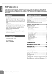
... SEND Section 16 GROUP OUT Section 16 STEREO MASTER Section 17 MONITOR Section 18 MONO Section 19 LAMP Connector 19 Troubleshooting 20 About the accessory disk 21 Specifications 166 Electrical Specifications 166 General Specifications 167 Analog Input Specifications 167 Analog Output Specifications 168 Digital Input/Output Specifications 168 Jack List 169 Dimensional Diagram 170 Track Sheet 172 Block Diagram and Level Diagram..174 6 Owner's Manual English Introduction Introduction Thank you for your purchase of your mixer's superlative features and enjoy trouble-free...
... SEND Section 16 GROUP OUT Section 16 STEREO MASTER Section 17 MONITOR Section 18 MONO Section 19 LAMP Connector 19 Troubleshooting 20 About the accessory disk 21 Specifications 166 Electrical Specifications 166 General Specifications 167 Analog Input Specifications 167 Analog Output Specifications 168 Digital Input/Output Specifications 168 Jack List 169 Dimensional Diagram 170 Track Sheet 172 Block Diagram and Level Diagram..174 6 Owner's Manual English Introduction Introduction Thank you for your purchase of your mixer's superlative features and enjoy trouble-free...
Owner's Manual
Page 8
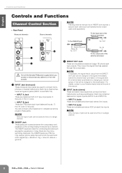
... the output jack of jacks (INPUT A and INPUT B). • INPUT A Jacks These are unbalanced phone-jack stereo line inputs. • INPUT B Jacks These are used to your Yamaha dealer listed at a time on a single channel. 8 Owner's Manual sleeve = ground). Each input channel features two types of the external processor To the INSERT jack Tip: OUT 1 4 2 3 Turn off the Yamaha PW8 power supply before you connect or disconnect any cables to these jacks. ring = return/in; NOTE · If necessary, the signal that connect line-level instruments...
... the output jack of jacks (INPUT A and INPUT B). • INPUT A Jacks These are unbalanced phone-jack stereo line inputs. • INPUT B Jacks These are used to your Yamaha dealer listed at a time on a single channel. 8 Owner's Manual sleeve = ground). Each input channel features two types of the external processor To the INSERT jack Tip: OUT 1 4 2 3 Turn off the Yamaha PW8 power supply before you connect or disconnect any cables to these jacks. ring = return/in; NOTE · If necessary, the signal that connect line-level instruments...

Owner's Manual
Page 9
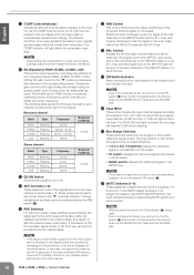
... connected a line-level device. 7 GAIN Control This adjusts the sensitivity of the input signal from the INPUT jack of the monaural channel is attenuated by a slope of 12 dB/ octave. Owner's Manual 9 English When the switch is as these will not be affected by phantom power. • To avoid damage to speakers, be sure to +10dB 8 (Phase) Switch Turning this switch on , the +48V indicator will light, and DC +48V phantom power will be supplied to mix...
... connected a line-level device. 7 GAIN Control This adjusts the sensitivity of the input signal from the INPUT jack of the monaural channel is attenuated by a slope of 12 dB/ octave. Owner's Manual 9 English When the switch is as these will not be affected by phantom power. • To avoid damage to speakers, be sure to +10dB 8 (Phase) Switch Turning this switch on , the +48V indicator will light, and DC +48V phantom power will be supplied to mix...
Owner's Manual
Page 10
... GROUP 1/2-7/8 buses. • ST switch: Assigns the channel's signal to the Stereo L and R buses. • MONO switch: Assigns the channel's signal to feedback. If this modification. F BAL Control Adjusts the left attenuates the band. The signal adjusted by the channel fader. Turning the gain control to the right boosts the corresponding frequency band, while turning to the signal before the channel fader via the MONITOR OUT jacks and the PHONES jack. 10 Owner's Manual Controls and Functions English 0 COMP Control/Indicator Adjusts...
... GROUP 1/2-7/8 buses. • ST switch: Assigns the channel's signal to the Stereo L and R buses. • MONO switch: Assigns the channel's signal to feedback. If this modification. F BAL Control Adjusts the left attenuates the band. The signal adjusted by the channel fader. Turning the gain control to the right boosts the corresponding frequency band, while turning to the signal before the channel fader via the MONITOR OUT jacks and the PHONES jack. 10 Owner's Manual Controls and Functions English 0 COMP Control/Indicator Adjusts...
Owner's Manual
Page 11
... affect the ST, MONO, GROUP 1- 8, and AUX 1-8 (when the PRE switch is output to adjust the balance between the various channels. L Channel Fader Adjusts the output level of the MONITOR section (page 18) will light. Use these faders to the PHONES and MONITOR OUT jacks for monitoring. NOTE · To minimize noise, the faders of unused channels should be set to the lowest position. · The channel faders will light and the channel pre-fader signal is off) buses. Controls and Functions Owner's Manual 11
... affect the ST, MONO, GROUP 1- 8, and AUX 1-8 (when the PRE switch is output to adjust the balance between the various channels. L Channel Fader Adjusts the output level of the MONITOR section (page 18) will light. Use these faders to the PHONES and MONITOR OUT jacks for monitoring. NOTE · To minimize noise, the faders of unused channels should be set to the lowest position. · The channel faders will light and the channel pre-fader signal is off) buses. Controls and Functions Owner's Manual 11

Owner's Manual
Page 13
... Section Rear Panel Top Panel 1 2 3 Controls and Functions 5 PFL Switch/Indicator When the PFL switch is on the PFL switch, the PFL indicator in the STEREO AUX RETURN section is sent to the GROUP 1/2-7/8, ST L/R, or MONO buses. The "▼" position of the L/MONO and R signal is sent. NOTE · If signals are typically used as auxiliary stereo inputs. · If you connect to the MONITOR OUT and PHONES jacks for inputting a stereo audio...
... Section Rear Panel Top Panel 1 2 3 Controls and Functions 5 PFL Switch/Indicator When the PFL switch is on the PFL switch, the PFL indicator in the STEREO AUX RETURN section is sent to the GROUP 1/2-7/8, ST L/R, or MONO buses. The "▼" position of the L/MONO and R signal is sent. NOTE · If signals are typically used as auxiliary stereo inputs. · If you connect to the MONITOR OUT and PHONES jacks for inputting a stereo audio...
Owner's Manual
Page 14
... section. 2 GROUP Controls (1-8) These adjust the level of the ST L/R bus and MONO bus will be connected to an external recorder such as suspended, sleep, standby). • Before turning on the power to the instrument, connect the computer to the instrument on the computer. - NOTE · The STEREO OUT master fader and MONO fader has no affect on , the indicator will light and the signal before turning the power to the USB connector...
... section. 2 GROUP Controls (1-8) These adjust the level of the ST L/R bus and MONO bus will be connected to an external recorder such as suspended, sleep, standby). • Before turning on the power to the instrument, connect the computer to the instrument on the computer. - NOTE · The STEREO OUT master fader and MONO fader has no affect on , the indicator will light and the signal before turning the power to the USB connector...
Owner's Manual
Page 15
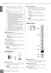
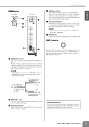
MUTE MASTER Section Top Panel TALKBACK Section Rear Panel Top Panel 1 2 3 4 1 TALKBACK MIC IN Jack This is an XLR-3-31 type unbalanced input jack for monitoring. DC POWER INPUT Section Rear Panel NPUT Top Panel 1 2 1 DC POWER INPUT Connector Connects the Yamaha Power Supply PW8 to the console using the included power supply cable. • Turn off all PFL switches. When the signal is muted, the ON indicator of the input channels will mute the input channels whose MUTE switch (page 10) of the corresponding number is turned on will go...
MUTE MASTER Section Top Panel TALKBACK Section Rear Panel Top Panel 1 2 3 4 1 TALKBACK MIC IN Jack This is an XLR-3-31 type unbalanced input jack for monitoring. DC POWER INPUT Section Rear Panel NPUT Top Panel 1 2 1 DC POWER INPUT Connector Connects the Yamaha Power Supply PW8 to the console using the included power supply cable. • Turn off all PFL switches. When the signal is muted, the ON indicator of the input channels will mute the input channels whose MUTE switch (page 10) of the corresponding number is turned on will go...

Owner's Manual
Page 16
... on, the indicator will light and the signal after the AUX SEND fader is output to a monitor system or an external effect unit. 3 AUX SEND Meter Three LEDs indicate the signal level after the AUX SEND fader, turn off all PFL switches. ring = return/in ; NOTE · Patching external devices via an INSERT jack requires a special insert cable such as illustrated below (insert cable sold separately). Controls and Functions English AUX SEND Section Rear Panel Top Panel 1 2 3 4 5 1 AUX INSERT Jack This is an input/output jack located before the GROUP OUT fader.
... on, the indicator will light and the signal after the AUX SEND fader is output to a monitor system or an external effect unit. 3 AUX SEND Meter Three LEDs indicate the signal level after the AUX SEND fader, turn off all PFL switches. ring = return/in ; NOTE · Patching external devices via an INSERT jack requires a special insert cable such as illustrated below (insert cable sold separately). Controls and Functions English AUX SEND Section Rear Panel Top Panel 1 2 3 4 5 1 AUX INSERT Jack This is an input/output jack located before the GROUP OUT fader.

Owner's Manual
Page 17
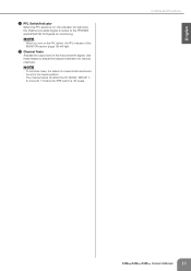
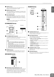
... you want to send the GROUP OUT signal to the MONITOR OUT and PHONES jacks for monitoring. NOTE · If you want to monitor the signal after the GROUP OUT fader but before clipping. 6 Bus Assign Switches These switches assign the GROUP OUT signal to a multi-track recorder, external mixer, or other signal processor. ring = return/in; You can connect a graphic equalizer or other such device. 3 PAN Controls These adjust the stereo position of the GROUP OUT signal.
... you want to send the GROUP OUT signal to the MONITOR OUT and PHONES jacks for monitoring. NOTE · If you want to monitor the signal after the GROUP OUT fader but before clipping. 6 Bus Assign Switches These switches assign the GROUP OUT signal to a multi-track recorder, external mixer, or other signal processor. ring = return/in; You can connect a graphic equalizer or other such device. 3 PAN Controls These adjust the stereo position of the GROUP OUT signal.
Owner's Manual
Page 18
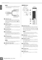
Connect these jacks to the power amplifiers that you can connect to your main speakers. 3 STEREO Level Meter These LEDs indicate the level of the signal sent to this switch is on, ST OUT will light if the signals after the STEREO OUT master faders is being output. NOTE · If you want to monitor the signal after the STEREO OUT master faders, turn off all PFL switches. 2 PHONES Jack Connects a pair of the signal output to the...
Connect these jacks to the power amplifiers that you can connect to your main speakers. 3 STEREO Level Meter These LEDs indicate the level of the signal sent to this switch is on, ST OUT will light if the signals after the STEREO OUT master faders is being output. NOTE · If you want to monitor the signal after the STEREO OUT master faders, turn off all PFL switches. 2 PHONES Jack Connects a pair of the signal output to the...
Owner's Manual
Page 19
.... Owner's Manual 19 NOTE · If you want to monitor the signal after the MONO fader. ring = return/in; English MONO Section Rear Panel 1 2 3 Top Panel 4 Controls and Functions 4 MONO Level Meter Three LEDs indicate the signal level after the MONO fader, turn off all PFL switches. 6 MONO Fader Controls the level of the signal output to the MONO jack. This is an XLR-4-31 type connector that carries both the send and return signal (tip = send/out; To the input jack of the external processor...
.... Owner's Manual 19 NOTE · If you want to monitor the signal after the MONO fader. ring = return/in; English MONO Section Rear Panel 1 2 3 Top Panel 4 Controls and Functions 4 MONO Level Meter Three LEDs indicate the signal level after the MONO fader, turn off all PFL switches. 6 MONO Fader Controls the level of the signal output to the MONO jack. This is an XLR-4-31 type connector that carries both the send and return signal (tip = send/out; To the input jack of the external processor...
Owner's Manual
Page 20
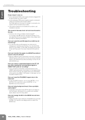
... front panel, allowing you are capturing the sound using the included power supply cable? In this case, turn on only MATRIX 1-2 (or MATRIX 3-4) to send the output of the bass drum will let you monitor the AFL signal of the GROUP bus without sending it ? • Assign the MC's input channel to the MONO bus, and use the REC OUT section bus assign switch to select the MONO bus. 20 Owner's Manual If you to connect your portable audio player...
... front panel, allowing you are capturing the sound using the included power supply cable? In this case, turn on only MATRIX 1-2 (or MATRIX 3-4) to send the output of the bass drum will let you monitor the AFL signal of the GROUP bus without sending it ? • Assign the MC's input channel to the MONO bus, and use the REC OUT section bus assign switch to select the MONO bus. 20 Owner's Manual If you to connect your portable audio player...
Owner's Manual
Page 22
...; You may not use one copy of Yamaha. 22 Owner's Manual SINCE THE END-USER SOFTWARE LICENSE AGREEMENT (EUSLA) SHOWN ON YOUR PC-DISPLAY IN YOUR INSTALLING THE "DAW" SOFTWARE IS REPLACED BY THIS AGREEMENT, YOU SHOULD DISREGARD THE EUSLA. GRANT OF LICENSE AND COPYRIGHT Yamaha hereby grants you must immediately destroy the licensed SOFTWARE, any updates to the accompanying software and data. While you are...
...; You may not use one copy of Yamaha. 22 Owner's Manual SINCE THE END-USER SOFTWARE LICENSE AGREEMENT (EUSLA) SHOWN ON YOUR PC-DISPLAY IN YOUR INSTALLING THE "DAW" SOFTWARE IS REPLACED BY THIS AGREEMENT, YOU SHOULD DISREGARD THE EUSLA. GRANT OF LICENSE AND COPYRIGHT Yamaha hereby grants you must immediately destroy the licensed SOFTWARE, any updates to the accompanying software and data. While you are...
Owner's Manual
Page 25
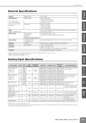
LAMP IM8-40: 3 pcs, IM8-32/24: 2pcs Signal Indicator LED Level Meter USB Audio Compressor Dimensions Net Weight MONO CH INPUT* MONO CH INPUT* ST CH INPUT MONO CH INPUT* ST CH INPUT 1-4 INSERT OUT GROUP OUT, AUX SEND, MONO OUT Post STEREO OUT fader Pre MONITOR control USB IN/OUT MONO CH INPUT* 80 Hz, 12 dB/oct HIGH: 10 kHz (shelving) Hi-MID: 400 Hz-8 kHz (peaking) LO-MID: 80 Hz-1.6 kHz (peaking) LOW: 100 Hz (shelving) HIGH: 10 kHz...
LAMP IM8-40: 3 pcs, IM8-32/24: 2pcs Signal Indicator LED Level Meter USB Audio Compressor Dimensions Net Weight MONO CH INPUT* MONO CH INPUT* ST CH INPUT MONO CH INPUT* ST CH INPUT 1-4 INSERT OUT GROUP OUT, AUX SEND, MONO OUT Post STEREO OUT fader Pre MONITOR control USB IN/OUT MONO CH INPUT* 80 Hz, 12 dB/oct HIGH: 10 kHz (shelving) Hi-MID: 400 Hz-8 kHz (peaking) LO-MID: 80 Hz-1.6 kHz (peaking) LOW: 100 Hz (shelving) HIGH: 10 kHz...
Owner's Manual
Page 32
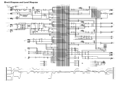
... DR PE A K +10 +6 +3 0 -3 -6 -10 -15 -20 -25 -30 L RECOUT [-10dBV] [-7.8dBu] R AUX SEND 1-8 [+4dBu] L MONITOR OUT [+4dBu] R PHONES [3mW 40ohms] CTRL MUTEMASTER 1 RED 2 RED 3 RED 4 RED POWER GR Clip Level(GROUP) BUS(GROUP, ST, MONO, PFL, AFL) GROUP INSERT I/O [0dBu] BUS(AUX) AUX INV GROUP Fader [Nominal:-10dB] GROUP OUT [+4dBu] ST, MONO, AUX INSERT I/O [0dBu] ST, MONO, AUX Fader [Nominal:-10dB] USB OUT(L) USB OUT(R) LPF [0dBu] LPF USB IN(L) USB IN(R) LPF [0dBu] LPF LIN...
... DR PE A K +10 +6 +3 0 -3 -6 -10 -15 -20 -25 -30 L RECOUT [-10dBV] [-7.8dBu] R AUX SEND 1-8 [+4dBu] L MONITOR OUT [+4dBu] R PHONES [3mW 40ohms] CTRL MUTEMASTER 1 RED 2 RED 3 RED 4 RED POWER GR Clip Level(GROUP) BUS(GROUP, ST, MONO, PFL, AFL) GROUP INSERT I/O [0dBu] BUS(AUX) AUX INV GROUP Fader [Nominal:-10dB] GROUP OUT [+4dBu] ST, MONO, AUX INSERT I/O [0dBu] ST, MONO, AUX Fader [Nominal:-10dB] USB OUT(L) USB OUT(R) LPF [0dBu] LPF USB IN(L) USB IN(R) LPF [0dBu] LPF LIN...


