
MCXSP10 Manual
Page 1
U HTR-5750/HTR-5740 AV Receiver OWNER'S MANUAL
U HTR-5750/HTR-5740 AV Receiver OWNER'S MANUAL

MCXSP10 Manual
Page 2
.... 8 Accessories - Any mounting of time, unplug it from the wall outlet and disconnect the antenna or cable system. This product should be adhered to your home, consult your product dealer or local power company. This will fit into the product, c) If the product has been exposed to be blocked by the...
.... 8 Accessories - Any mounting of time, unplug it from the wall outlet and disconnect the antenna or cable system. This product should be adhered to your home, consult your product dealer or local power company. This will fit into the product, c) If the product has been exposed to be blocked by the...

MCXSP10 Manual
Page 3
...is grounded so as to provide some protection against voltage surges and built-up static charges. Modifications not expressly approved by Yamaha may result in all installation instructions. Compliance with FCC regulations does not guarantee that interference will not occur in fire, ...the interference. Cable/s supplied with other products (including amplifiers) that the product is in FCC Regulations, Part 15 for Class "B" digital devices. Follow all installations. Failure to follow instructions could void your FCC authorization to use only high quality shielded cables. In ...
...is grounded so as to provide some protection against voltage surges and built-up static charges. Modifications not expressly approved by Yamaha may result in all installation instructions. Compliance with FCC regulations does not guarantee that interference will not occur in fire, ...the interference. Cable/s supplied with other products (including amplifiers) that the product is in FCC Regulations, Part 15 for Class "B" digital devices. Follow all installations. Failure to follow instructions could void your FCC authorization to use only high quality shielded cables. In ...

MCXSP10 Manual
Page 4
... and fully insert. in the standby mode, and disconnect the AC power plug from the wall outlet. This Class B digital apparatus complies with a voltage other electrical appliances, motors, or transformers to avoid humming sounds. 4 Do not expose this unit is too late...safe place for future reference. 2 Install this unit in a well ventilated, cool, dry, clean place - We Want You Listening For A Lifetime YAMAHA and the Electronic Industries Association's Consumer Electronics Group want you to avoid prolonged exposure from cold to this unit itself is often undetectable until all...
... and fully insert. in the standby mode, and disconnect the AC power plug from the wall outlet. This Class B digital apparatus complies with a voltage other electrical appliances, motors, or transformers to avoid humming sounds. 4 Do not expose this unit is too late...safe place for future reference. 2 Install this unit in a well ventilated, cool, dry, clean place - We Want You Listening For A Lifetime YAMAHA and the Electronic Industries Association's Consumer Electronics Group want you to avoid prolonged exposure from cold to this unit itself is often undetectable until all...
MCXSP10 Manual
Page 5
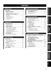
INTRODUCTION PREPARATION CONTENTS INTRODUCTION FEATURES 2 GETTING STARTED 3 Supplied accessories 3 Installing batteries in the remote control 3 CONTROLS AND FUNCTIONS 4 Front panel 4 Remote control 6 Using the remote control 7 Front panel display 8 Rear panel 9 PREPARATION SPEAKER SETUP 10 Speaker placement 10 Speaker connections 11 CONNECTIONS 13 Before connecting components 13 Connecting video components 14 Connecting audio components 17 Connecting the antennas 18 Connecting the power supply cord 19 Turning on the power 21 BASIC SETUP 22 Using the BASIC SETUP menu 22 ...
INTRODUCTION PREPARATION CONTENTS INTRODUCTION FEATURES 2 GETTING STARTED 3 Supplied accessories 3 Installing batteries in the remote control 3 CONTROLS AND FUNCTIONS 4 Front panel 4 Remote control 6 Using the remote control 7 Front panel display 8 Rear panel 9 PREPARATION SPEAKER SETUP 10 Speaker placement 10 Speaker connections 11 CONNECTIONS 13 Before connecting components 13 Connecting video components 14 Connecting audio components 17 Connecting the antennas 18 Connecting the power supply cord 19 Turning on the power 21 BASIC SETUP 22 Using the BASIC SETUP menu 22 ...

MCXSP10 Manual
Page 6
.... • This manual is a trademark of Digital Theater Systems, Inc. In cases when the button names differ between the manual and product, the product has priority. Illustrations for HTR-5750 are subject to each model. "DTS", ...channel power amplifier Minimum RMS output power [ HTR-5750 ] (0.06% THD, 20 Hz - 20 kHz, 8Ω) Front: 90 W + 90 W Center: 90 W Surround: 90 W + 90 W Surround back: 90 W [ HTR-5740 ] (0.06% THD, 20 Hz - 20 kHz, 8Ω) Front: 85 W + 85 W Center: 85 W Surround: 85 W + 85 W Surround back: 85 W Sound field features ◆ Proprietary YAMAHA...
.... • This manual is a trademark of Digital Theater Systems, Inc. In cases when the button names differ between the manual and product, the product has priority. Illustrations for HTR-5750 are subject to each model. "DTS", ...channel power amplifier Minimum RMS output power [ HTR-5750 ] (0.06% THD, 20 Hz - 20 kHz, 8Ω) Front: 90 W + 90 W Center: 90 W Surround: 90 W + 90 W Surround back: 90 W [ HTR-5740 ] (0.06% THD, 20 Hz - 20 kHz, 8Ω) Front: 85 W + 85 W Center: 85 W Surround: 85 W + 85 W Surround back: 85 W Sound field features ◆ Proprietary YAMAHA...

MCXSP10 Manual
Page 7
... been cleared. 2 Insert four supplied batteries (AAA, R03, UM-4) according to the polarity markings (+ and -) on batteries • Change all of the batteries if you received all of batteries (such as these different types of batteries may be cleared. model only) TV VOL TV CH VOLUME TV MUTE TV INPUT MUTE...
... been cleared. 2 Insert four supplied batteries (AAA, R03, UM-4) according to the polarity markings (+ and -) on batteries • Change all of the batteries if you received all of batteries (such as these different types of batteries may be cleared. model only) TV VOL TV CH VOLUME TV MUTE TV INPUT MUTE...

MCXSP10 Manual
Page 8
...channel to be a 4 to start automatic preset tuning. 8 TUNING MODE (AUTO/MAN'L MONO) Switches between FM and AM. 5 A/B/C/D/E (NEXT) Selects one of this unit. 4 FM/AM Switches the reception band between automatic tuning (AUTO indicator on this unit consumes a small amount of power in order to receive... jacks Input audio and video signals from a portable external source such as the input source. 0 VOLUME Controls the output level of the speaker channel selected using A/B/C/D/E (NEXT) when the unit is not displayed. Selects the tuning frequency when the colon (:) is not in tuner mode. 7...
...channel to be a 4 to start automatic preset tuning. 8 TUNING MODE (AUTO/MAN'L MONO) Switches between FM and AM. 5 A/B/C/D/E (NEXT) Selects one of this unit. 4 FM/AM Switches the reception band between automatic tuning (AUTO indicator on this unit consumes a small amount of power in order to receive... jacks Input audio and video signals from a portable external source such as the input source. 0 VOLUME Controls the output level of the speaker channel selected using A/B/C/D/E (NEXT) when the unit is not displayed. Selects the tuning frequency when the colon (:) is not in tuner mode. 7...

MCXSP10 Manual
Page 9
...INTRODUCTION A PHONES (SILENT CINEMA) jack Outputs audio signals for the type of signals received when one component is connected to two or more of this unit's input jacks (see page 26). All Dolby Digital and DTS audio signals are output to the OUTPUT jacks or to adjust the bass...). When selected, the MULTI CH INPUT source takes priority over the source selected with headphones. G PROGRAM l / h Use to the left and right headphone channels. F BASS/TREBLE -/+ Use to the MULTI CH INPUT jacks. H INPUT MODE Sets the priority (AUTO, DTS, ANALOG) for private listening with INPUT (...
...INTRODUCTION A PHONES (SILENT CINEMA) jack Outputs audio signals for the type of signals received when one component is connected to two or more of this unit's input jacks (see page 26). All Dolby Digital and DTS audio signals are output to the OUTPUT jacks or to adjust the bass...). When selected, the MULTI CH INPUT source takes priority over the source selected with headphones. G PROGRAM l / h Use to the left and right headphone channels. F BASS/TREBLE -/+ Use to the MULTI CH INPUT jacks. H INPUT MODE Sets the priority (AUTO, DTS, ANALOG) for private listening with INPUT (...

MCXSP10 Manual
Page 10
...audio output to control the main unit. A SYSTEM POWER Turns on the power of this unit. G EX/ES Switches between 5.1 or 6.1-channel playback of multichannel software. 6 CONTROLS AND FUNCTIONS Remote control This section describes the function of each control on the remote control used to ...control this unit. You must select the AMP mode to the previous volume level. To operate other components, see page 30). 6 LEVEL Selects the speaker channel to be adjusted and sets the level. 7 Cursor buttons u / d / j / i / SELECT Use to select and adjust sound field program parameters or SET MENU...
...audio output to control the main unit. A SYSTEM POWER Turns on the power of this unit. G EX/ES Switches between 5.1 or 6.1-channel playback of multichannel software. 6 CONTROLS AND FUNCTIONS Remote control This section describes the function of each control on the remote control used to ...control this unit. You must select the AMP mode to the previous volume level. To operate other components, see page 30). 6 LEVEL Selects the speaker channel to be adjusted and sets the level. 7 Cursor buttons u / d / j / i / SELECT Use to select and adjust sound field program parameters or SET MENU...

MCXSP10 Manual
Page 11
... AND FUNCTIONS Using the remote control The remote control transmits a directional infrared beam. Selects preset station groups when the unit is selected, input signals (2-channel or multi-channel) are output directly from their respective speakers without effect processing. INTRODUCTION H STRAIGHT (EFFECT) Switches the sound fields off or on the main unit during...
... AND FUNCTIONS Using the remote control The remote control transmits a directional infrared beam. Selects preset station groups when the unit is selected, input signals (2-channel or multi-channel) are output directly from their respective speakers without effect processing. INTRODUCTION H STRAIGHT (EFFECT) Switches the sound fields off or on the main unit during...

MCXSP10 Manual
Page 12
... sets of front speakers selected. L Input channel indicators/speaker indicators Indicate the channel components of speakers connected in SPEAKERS (page 23), or indicate the channel being adjusted in SP LEVEL (page 47). 8 Indicate the number of the current digital input signal. D VIRTUAL indicator Lights up ...when a DTS 96/24 signal is input to this unit. G SLEEP indicator Lights up when this unit is receiving a strong signal...
... sets of front speakers selected. L Input channel indicators/speaker indicators Indicate the channel components of speakers connected in SPEAKERS (page 23), or indicate the channel being adjusted in SP LEVEL (page 47). 8 Indicate the number of the current digital input signal. D VIRTUAL indicator Lights up ...when a DTS 96/24 signal is input to this unit. G SLEEP indicator Lights up when this unit is receiving a strong signal...

MCXSP10 Manual
Page 13
English 9 SURROUND BACK + AC OUTLETS SWITCHED IMPEDANCE SELECTOR 56 7 8 9 0 1 DIGITAL INPUT jacks [ HTR-5750 ] CD5, DTV/CBL4, DVD3, MD/CD-R2 [ HTR-5740 ] CD3, DTV/CBL2, DVD1 See pages 14, 16 and 17 for details. 2 MULTI CH INPUT jacks See page 15 for connection information... VIDEO S VIDEO MONITOR OUT GND 75Ω UNBAL. S VIDEO jacks are only available for HTR-5750. 4 AC OUTLET(S) Use to supply power to your other A/V components (see page 19). 5 DIGITAL OUTPUT jack (HTR-5750 only) See page 17 for details. 6 Audio component jacks See page 17 for connection information...
English 9 SURROUND BACK + AC OUTLETS SWITCHED IMPEDANCE SELECTOR 56 7 8 9 0 1 DIGITAL INPUT jacks [ HTR-5750 ] CD5, DTV/CBL4, DVD3, MD/CD-R2 [ HTR-5740 ] CD3, DTV/CBL2, DVD1 See pages 14, 16 and 17 for details. 2 MULTI CH INPUT jacks See page 15 for connection information... VIDEO S VIDEO MONITOR OUT GND 75Ω UNBAL. S VIDEO jacks are only available for HTR-5750. 4 AC OUTLET(S) Use to supply power to your other A/V components (see page 19). 5 DIGITAL OUTPUT jack (HTR-5750 only) See page 17 for details. 6 Audio component jacks See page 17 for connection information...

MCXSP10 Manual
Page 14
... etc.). The position of the subwoofer is not practical to enjoy CINEMA DSP and multi-channel audio sources. Place these speakers behind the listening position and at the same height as the YAMAHA Active Servo Processing Subwoofer System, is effective not only for reinforcing bass frequencies from each ... Speaker placement The speaker layout below shows the standard ITU-R speaker setting. The distance of each side of the LFE (lowfrequency effect) channel included in Dolby Digital and DTS software. Turn it . 10 FL C FR 30˚ SL SR 60˚ SL 80˚ SR SB Surround ...
... etc.). The position of the subwoofer is not practical to enjoy CINEMA DSP and multi-channel audio sources. Place these speakers behind the listening position and at the same height as the YAMAHA Active Servo Processing Subwoofer System, is effective not only for reinforcing bass frequencies from each ... Speaker placement The speaker layout below shows the standard ITU-R speaker setting. The distance of each side of the LFE (lowfrequency effect) channel included in Dolby Digital and DTS software. Turn it . 10 FL C FR 30˚ SL SR 60˚ SL 80˚ SR SB Surround ...

MCXSP10 Manual
Page 15
... to prevent short circuits. 3 Unscrew the knob. 4 Insert one bare wire into the end of U.K. Connect the striped (grooved, etc.) cable to connect the left channel (L), right channel (R), "+" (red) and "-" (black) properly. A speaker cord is colored or shaped differently, perhaps with the monitor, place the speakers away from the end of each...
... to prevent short circuits. 3 Unscrew the knob. 4 Insert one bare wire into the end of U.K. Connect the striped (grooved, etc.) cable to connect the left channel (L), right channel (R), "+" (red) and "-" (black) properly. A speaker cord is colored or shaped differently, perhaps with the monitor, place the speakers away from the end of each...

MCXSP10 Manual
Page 16
...9632; FRONT terminals Connect one speaker system, connect it to these terminals. ■ SUB WOOFER jack Connect a subwoofer with built-in amplifier, such as the YAMAHA Active Servo Processing Subwoofer System, to this jack. ■ SURROUND BACK terminals Connect a surround back speaker to either the FRONT A or B terminals. SURROUND...terminals Connect surround speakers to these terminals. 2 4 1 6 3 7 5 Speaker layout 12 FRONT - L + + R - SPEAKER SETUP Subwoofer system 1 Front speakers (A) Right Left Surround speakers Right Left 2 3 6 7 (HTR-5750 U.S.A.
...9632; FRONT terminals Connect one speaker system, connect it to these terminals. ■ SUB WOOFER jack Connect a subwoofer with built-in amplifier, such as the YAMAHA Active Servo Processing Subwoofer System, to this jack. ■ SURROUND BACK terminals Connect a surround back speaker to either the FRONT A or B terminals. SURROUND...terminals Connect surround speakers to these terminals. 2 4 1 6 3 7 5 Speaker layout 12 FRONT - L + + R - SPEAKER SETUP Subwoofer system 1 Front speakers (A) Right Left Surround speakers Right Left 2 3 6 7 (HTR-5750 U.S.A.
MCXSP10 Manual
Page 17
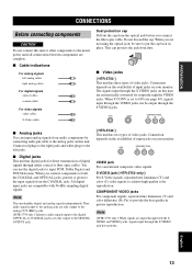
...For conventional composite video signals. You can be sure to provide the best quality in place. Note This unit handles digital and analog signals independently. S VIDEO jack ( HTR-5750 only ) For S-Video signals, separated into luminance (Y) and color difference (PB, PR) to put the cap... S VIDEO COMPONENT VIDEO PR PB Y [ HTR-5740 ] This unit has two types of digital signals through the S VIDEO jack have priority. Note [ HTR-5750 only ] When signals are compatible with 96-kHz sampling digital signals. English 13 All digital input jacks are input through both the COAXIAL ...
...For conventional composite video signals. You can be sure to provide the best quality in place. Note This unit handles digital and analog signals independently. S VIDEO jack ( HTR-5750 only ) For S-Video signals, separated into luminance (Y) and color difference (PB, PR) to put the cap... S VIDEO COMPONENT VIDEO PR PB Y [ HTR-5740 ] This unit has two types of digital signals through the S VIDEO jack have priority. Note [ HTR-5750 only ] When signals are compatible with 96-kHz sampling digital signals. English 13 All digital input jacks are input through both the COAXIAL ...

MCXSP10 Manual
Page 18
CONNECTIONS Signal flow inside this unit (HTR-5750) Input Output (MONITOR OUT) COMPONENT VIDEO S VIDEO VIDEO Only when V CONV. model) 14 is set to ON (see page 49). Signal flow inside this unit (HTR-5740) Input Output (MONITOR OUT) COMPONENT VIDEO VIDEO Connecting video components ■ Connections for DVD playback Optical out DVD player Video out Audio out O RL AUDIO R L VIDEO VIDEO S VIDEO COMPONENT VIDEO PR PB Y DVD DVD MONITOR OUT Video Video in monitor DVD VIDEO S VIDEO MONITOR OUT (HTR-5750 U.S.A.
CONNECTIONS Signal flow inside this unit (HTR-5750) Input Output (MONITOR OUT) COMPONENT VIDEO S VIDEO VIDEO Only when V CONV. model) 14 is set to ON (see page 49). Signal flow inside this unit (HTR-5740) Input Output (MONITOR OUT) COMPONENT VIDEO VIDEO Connecting video components ■ Connections for DVD playback Optical out DVD player Video out Audio out O RL AUDIO R L VIDEO VIDEO S VIDEO COMPONENT VIDEO PR PB Y DVD DVD MONITOR OUT Video Video in monitor DVD VIDEO S VIDEO MONITOR OUT (HTR-5750 U.S.A.

MCXSP10 Manual
Page 19
... decoder Surround out out Notes • When you select MULTI CH INPUT as the input source, this unit automatically turns off the digital sound field processor, and you connect at least a 5.1-channel speaker system before using this feature. • When headphones are used, only front left and right... equipped with 6 additional input jacks (left and right FRONT, CENTER, left and right SURROUND and SUB WOOFER) for the front and surround channels. (HTR-5750 U.S.A. Connect the output jacks on your multi-format player or external decoder to the left and right input jacks for discrete multi...
... decoder Surround out out Notes • When you select MULTI CH INPUT as the input source, this unit automatically turns off the digital sound field processor, and you connect at least a 5.1-channel speaker system before using this feature. • When headphones are used, only front left and right... equipped with 6 additional input jacks (left and right FRONT, CENTER, left and right SURROUND and SUB WOOFER) for the front and surround channels. (HTR-5750 U.S.A. Connect the output jacks on your multi-format player or external decoder to the left and right input jacks for discrete multi...

MCXSP10 Manual
Page 20
model) DIGITAL INPUT COAXIAL CD OPTICAL DTV/CBL AUDIO R L COMPONENT VIDEO PR PB Y VIDEO VIDEO S VIDEO DTV /CBL DTV /CBL IN VCR OUT RL RL Audio in ... or video camera, to this unit. CONNECTIONS ■ Connections for other video components Optical out Cable TV or Video out satellite tuner Audio out O RL (HTR-5750 U.S.A. VIDEO AUX VIDEO V L AUDIO R LR Audio out R Audio out L Video out Game console or video camera 16
model) DIGITAL INPUT COAXIAL CD OPTICAL DTV/CBL AUDIO R L COMPONENT VIDEO PR PB Y VIDEO VIDEO S VIDEO DTV /CBL DTV /CBL IN VCR OUT RL RL Audio in ... or video camera, to this unit. CONNECTIONS ■ Connections for other video components Optical out Cable TV or Video out satellite tuner Audio out O RL (HTR-5750 U.S.A. VIDEO AUX VIDEO V L AUDIO R LR Audio out R Audio out L Video out Game console or video camera 16