
Owner's Manual
Page 2
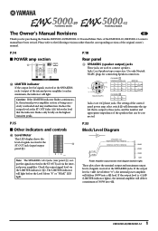
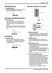
... The LIMITER indicator will deliver a maximum of the EMX5000-20, EMX5000-12 owner's manual have been revised. If the output level is being excessively overloaded and may malfunction. CHANNEL A STEREO/PARALLEL 2- 1+ A+ 2+ 1- B- 1- Neutrik NL4FC CHANNEL B 1+ B+ 1- Check the output signal level ...ST OUT jack via the LIMITER indicator (X). BRIDGE 1+ + 1- 2+ - 2- Use only Neutrik NL4FC plugs for purchasing the Yamaha EMX5000-20/EMX5000-12 Powered Mixer. P.14 ■ POWER amp section X X LIMITER indicator If the output level of signals received at the ...
... The LIMITER indicator will deliver a maximum of the EMX5000-20, EMX5000-12 owner's manual have been revised. If the output level is being excessively overloaded and may malfunction. CHANNEL A STEREO/PARALLEL 2- 1+ A+ 2+ 1- B- 1- Neutrik NL4FC CHANNEL B 1+ B+ 1- Check the output signal level ...ST OUT jack via the LIMITER indicator (X). BRIDGE 1+ + 1- 2+ - 2- Use only Neutrik NL4FC plugs for purchasing the Yamaha EMX5000-20/EMX5000-12 Powered Mixer. P.14 ■ POWER amp section X X LIMITER indicator If the output level of signals received at the ...
Owner's Manual
Page 7
... drive. This lets you for a wide range of applications from installed systems to smallscale PA systems. • A two-channel power amp is suitable for purchasing the Yamaha EMX5000-20/EMX5000-12 Powered Mixer. Contents Introduction 5 Features 5 EMX5000-20/EMX5000-12 Quick Guide 6 Front and rear panel 10 Control panel 10 Input/output panel 16 Rear panel 18 Installation...
... drive. This lets you for a wide range of applications from installed systems to smallscale PA systems. • A two-channel power amp is suitable for purchasing the Yamaha EMX5000-20/EMX5000-12 Powered Mixer. Contents Introduction 5 Features 5 EMX5000-20/EMX5000-12 Quick Guide 6 Front and rear panel 10 Control panel 10 Input/output panel 16 Rear panel 18 Installation...
Owner's Manual
Page 9
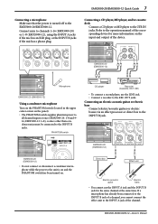
... turned on. Connect mics to the REC OUT jacks. If a microphone has already been connected to the INPUT B jack of a channel, you cannot connect the effect unit to the EMX5000-20/EMX5000-12. EMX5000-20 (EMX5000-12) Direct box Effect unit Electric-acoustic guitar Electric bass • You cannot use the LINE jack. • Connect a recorder to...
... turned on. Connect mics to the REC OUT jacks. If a microphone has already been connected to the INPUT B jack of a channel, you cannot connect the effect unit to the EMX5000-20/EMX5000-12. EMX5000-20 (EMX5000-12) Direct box Effect unit Electric-acoustic guitar Electric bass • You cannot use the LINE jack. • Connect a recorder to...
Owner's Manual
Page 10
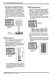
...to all external devices connected to the EMX5000-20/EMX5000-12. 2 Make sure that the ST OUT fader of the EMX5000-20/EMX5000-12 is lowered, and then press the POWER switch of the EMX5000-20/ EMX5000-12 to adjust the volume. • Please be aware that channel lights occasionally. • Do not... the "0" position, and raise the faders of the panel. Otherwise, press the 26dB PAD switch on the YAMAHA SPEAKER PROCESSING switch in stereo. EMX5000-20 (EMX5000-12) EMX5000-20 (EMX5000-12) • Be sure to follow the power up sequence specified above to prevent the speakers from the...
...to all external devices connected to the EMX5000-20/EMX5000-12. 2 Make sure that the ST OUT fader of the EMX5000-20/EMX5000-12 is lowered, and then press the POWER switch of the EMX5000-20/ EMX5000-12 to adjust the volume. • Please be aware that channel lights occasionally. • Do not... the "0" position, and raise the faders of the panel. Otherwise, press the 26dB PAD switch on the YAMAHA SPEAKER PROCESSING switch in stereo. EMX5000-20 (EMX5000-12) EMX5000-20 (EMX5000-12) • Be sure to follow the power up sequence specified above to prevent the speakers from the...
Owner's Manual
Page 11
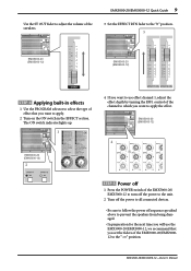
... control of the channel to which you want to apply. 2 Turn on the ON switch in effects 1 Use the PROGRAM selector to select the type of effect that you want to apply the effect. The ON switch indicator lights up. 1 EMX5000-20 (EMX5000-12) 2 4 If you want to use the EMX5000-20/EMX5000-12, we recommend that...
... control of the channel to which you want to apply. 2 Turn on the ON switch in effects 1 Use the PROGRAM selector to select the type of effect that you want to apply the effect. The ON switch indicator lights up. 1 EMX5000-20 (EMX5000-12) 2 4 If you want to use the EMX5000-20/EMX5000-12, we recommend that...
Owner's Manual
Page 12
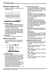
...177;15 dB, shelving type MID: 250Hz-5kHz, ±15 dB, peaking type LOW: 100Hz, ±15 dB, shelving type EMX5000-20/EMX5000-12-Owner's Manual Turning the lower knob toward the right will boost the corresponding frequency range, and turning the knob toward the left will ... boost the corresponding frequency range, and turning it toward the left will cut it . Attenuation is on /off switch for the input signal of each channel. 1 2* 2 3 4 4 5 5 6 6 7 8 9 9 0 0 A A B B C C 1 26 dB pad switch This switch attenuates the input signal by 26 dB. The high-pass fi...
...177;15 dB, shelving type MID: 250Hz-5kHz, ±15 dB, peaking type LOW: 100Hz, ±15 dB, shelving type EMX5000-20/EMX5000-12-Owner's Manual Turning the lower knob toward the right will boost the corresponding frequency range, and turning the knob toward the left will ... boost the corresponding frequency range, and turning it toward the left will cut it . Attenuation is on /off switch for the input signal of each channel. 1 2* 2 3 4 4 5 5 6 6 7 8 9 9 0 0 A A B B C C 1 26 dB pad switch This switch attenuates the input signal by 26 dB. The high-pass fi...
Owner's Manual
Page 13
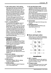
...that are sent to the ST SUB IN 1, 2 jacks on , you can be set by the setting of the channel fader C (post-fader send). 7 PAN (panpot) control (EMX5000-20: Channels 1-16, EMX5000-12: Channels 1-8) The PAN knobs set the stereo position of the EFFECT 1, 2 control, but also by the POST switch to the... when the knob is positioned at "w," at right at R, and at left at L. 8 BAL (balance) control (EMX5000-20: Channels 17/18-19/20, EMX5000-12: Channels 9/10-11/12) The BAL knobs set the balance between the left and right channels, and assign the signals received at inputs 17/18-19/20, 9/10-11...
...that are sent to the ST SUB IN 1, 2 jacks on , you can be set by the setting of the channel fader C (post-fader send). 7 PAN (panpot) control (EMX5000-20: Channels 1-16, EMX5000-12: Channels 1-8) The PAN knobs set the stereo position of the EFFECT 1, 2 control, but also by the POST switch to the... when the knob is positioned at "w," at right at R, and at left at L. 8 BAL (balance) control (EMX5000-20: Channels 17/18-19/20, EMX5000-12: Channels 9/10-11/12) The BAL knobs set the balance between the left and right channels, and assign the signals received at inputs 17/18-19/20, 9/10-11...
Owner's Manual
Page 16
... these signals is output to adjust the frequency response of the STEREO bus signal, providing a maximum of ±12 dB of the following three settings to specify the signals to be sent to the speaker connection at the SPEAKERS ... panel C). This graphic equalizer affects both the STEREO bus signal that is significantly overloaded, which could result in two-channel power amplifier. X Y Z X LIMITER indicator This indicator lights up when the level of the two...will be routed to the corresponding jacks according to the built-in malfunction. EMX5000-20/EMX5000-12-Owner's Manual
... these signals is output to adjust the frequency response of the STEREO bus signal, providing a maximum of ±12 dB of the following three settings to specify the signals to be sent to the speaker connection at the SPEAKERS ... panel C). This graphic equalizer affects both the STEREO bus signal that is significantly overloaded, which could result in two-channel power amplifier. X Y Z X LIMITER indicator This indicator lights up when the level of the two...will be routed to the corresponding jacks according to the built-in malfunction. EMX5000-20/EMX5000-12-Owner's Manual
Owner's Manual
Page 17
...OUT jack. c LPF control, ON/OFF switch This switch applies a low-pass filter to the signal that is output from channels 1-16 (EMX5000-20) or channels 1-8 (EMX5000-12). This will output the region below the frequency (80-120 Hz) you specify by the position of the slit in the control trimmer... the output level reaches +4 dB. The low range balance when this switch is on varies depending on . [ s Other indicators and controls ` s YAMAHA SPEAKER PROCESSING \ ON/OFF switch This switch enables you to compensate the low range of the speakers. b ST SUB OUT control This knob adjusts the...
...OUT jack. c LPF control, ON/OFF switch This switch applies a low-pass filter to the signal that is output from channels 1-16 (EMX5000-20) or channels 1-8 (EMX5000-12). This will output the region below the frequency (80-120 Hz) you specify by the position of the slit in the control trimmer... the output level reaches +4 dB. The low range balance when this switch is on varies depending on . [ s Other indicators and controls ` s YAMAHA SPEAKER PROCESSING \ ON/OFF switch This switch enables you to compensate the low range of the speakers. b ST SUB OUT control This knob adjusts the...
Owner's Manual
Page 18
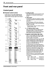
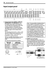
...The nominal input/output levels are compatible with microphones of output impedance 50-600Ω or line level devices of channels or channel 17/18-19/20 (EMX5000-20), 9/10-11/ 12 (EMX5000-12) input jacks if the PHANTOM +48V switch (control panel 3) is on. 2 INSERT I /O jack Sleeve... to simultaneously use condenser microphones. 16 Front and rear panel Input/output panel 1 3 4 56 8 0 A E F G 2 1 Channel input jacks (INPUT A, INPUT B) EMX5000-20: 1-16, EMX5000-12: 1-8 By using the GAIN control (control panel 2) you can connect any of the jacks to a wide range of the external processor...
...The nominal input/output levels are compatible with microphones of output impedance 50-600Ω or line level devices of channels or channel 17/18-19/20 (EMX5000-20), 9/10-11/ 12 (EMX5000-12) input jacks if the PHANTOM +48V switch (control panel 3) is on. 2 INSERT I /O jack Sleeve... to simultaneously use condenser microphones. 16 Front and rear panel Input/output panel 1 3 4 56 8 0 A E F G 2 1 Channel input jacks (INPUT A, INPUT B) EMX5000-20: 1-16, EMX5000-12: 1-8 By using the GAIN control (control panel 2) you can connect any of the jacks to a wide range of the external processor...
Owner's Manual
Page 19
...-in the upper part of channels 1-8 and 9-16 (on the EMX5000-20) or channels 1-8 (on the recording device. 7 ST SUB IN 1 (stereo sub 1) jacks ST SUB IN 2 (stereo sub 2) jacks These phone jacks are connecting. E FOOT SW EFFECT 2 ON/OFF jack A separately sold Yamaha FC5 foot switch can connect either... allow the signal from this jack. When this jack, the corresponding channel of the power amplifier will be isolated, and no signals will light. 4 LINE (stereo) input jacks EMX5000-20: 17/18-19/20, EMX5000-12: 9/10-11/12 These are the input jacks for the phantom power supplied to the...
...-in the upper part of channels 1-8 and 9-16 (on the EMX5000-20) or channels 1-8 (on the recording device. 7 ST SUB IN 1 (stereo sub 1) jacks ST SUB IN 2 (stereo sub 2) jacks These phone jacks are connecting. E FOOT SW EFFECT 2 ON/OFF jack A separately sold Yamaha FC5 foot switch can connect either... allow the signal from this jack. When this jack, the corresponding channel of the power amplifier will be isolated, and no signals will light. 4 LINE (stereo) input jacks EMX5000-20: 17/18-19/20, EMX5000-12: 9/10-11/12 These are the input jacks for the phantom power supplied to the...
Owner's Manual
Page 20
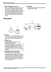
... voltage printed below the inlet. 2 POWER switch This switch turns on/off , the faders and controls in the master section of the EMX5000-20/EMX5000-12 on or off the power to the corresponding interval. Note: Before you turn the power of the control panel must be lowered to the... press the foot switch to set to this inlet. Jacks 1 are 1/4" phone jacks. EMX5000-20/EMX5000-12-Owner's Manual Rear panel G LAMP jack This is selected as the internal effect type for the EFFECT 2 RTN channel, you press the foot switch several times, the delay time will determine the signal that is...
... voltage printed below the inlet. 2 POWER switch This switch turns on/off , the faders and controls in the master section of the EMX5000-20/EMX5000-12 on or off the power to the corresponding interval. Note: Before you turn the power of the control panel must be lowered to the... press the foot switch to set to this inlet. Jacks 1 are 1/4" phone jacks. EMX5000-20/EMX5000-12-Owner's Manual Rear panel G LAMP jack This is selected as the internal effect type for the EFFECT 2 RTN channel, you press the foot switch several times, the delay time will determine the signal that is...
Owner's Manual
Page 21
... and the STEREO bus will be output from the speakers connected to these jacks. Installation/Connections 19 Installation/Connections Installation The EMX5000-20/EMX5000-12 uses a forced cooling system with an impedance in which speakers can be connected to speaker jacks. Make connections to make ...sure the speaker impedance will be combined and output as a monaural signal from the speakers connected to these respective jacks. • Two channel...
... and the STEREO bus will be output from the speakers connected to these jacks. Installation/Connections 19 Installation/Connections Installation The EMX5000-20/EMX5000-12 uses a forced cooling system with an impedance in which speakers can be connected to speaker jacks. Make connections to make ...sure the speaker impedance will be combined and output as a monaural signal from the speakers connected to these respective jacks. • Two channel...
Owner's Manual
Page 22
...speaker is set to MONO BRIDGE: • Bridge connection Connect only one 8-16 ohm speaker to the A1 jack. Two-channel connection Two-channel parallel connection or 4Ω-8Ω 4Ω-8Ω 8Ω-16Ω 8Ω-16Ω 8Ω-16Ω 8Ω...and . * Use either the 1 (Speakon) jacks or 2 (phone) jacks of the 1 jack. 8Ω-16Ω Main Speaker EMX5000-20/EMX5000-12-Owner's Manual 20 Installation/Connections • Two channel parallel connections If you are used . Caution: When using a bridge connection, do not connect a speaker to the B or A 2...
...speaker is set to MONO BRIDGE: • Bridge connection Connect only one 8-16 ohm speaker to the A1 jack. Two-channel connection Two-channel parallel connection or 4Ω-8Ω 4Ω-8Ω 8Ω-16Ω 8Ω-16Ω 8Ω-16Ω 8Ω...and . * Use either the 1 (Speakon) jacks or 2 (phone) jacks of the 1 jack. 8Ω-16Ω Main Speaker EMX5000-20/EMX5000-12-Owner's Manual 20 Installation/Connections • Two channel parallel connections If you are used . Caution: When using a bridge connection, do not connect a speaker to the B or A 2...

Owner's Manual
Page 24
.... 6 Adjust the PARAMETER control of the cables firmly into the appropriate INPUT A/B jacks (EMX5000-20: channels 1-16, EMX5000-12: channels 1-8) or the 17L/ 18R, 19L/20R (EMX5000-20), 9L/10R, 11L/12R (EMX5000-12) jacks. Note: When turning the power off . 22 Basic operation Basic operation Connecting microphones and ...of the digital effect section to adjust the level of the AUX 1/2 fader in the digital effect section. Note: You cannot use channel 1-16 (EMX5000-20), 1-8 (EMX5000-12) INPUT A and B jacks at the maximum volume. 5 Raise the ST OUT fader in the master section to the "10...
.... 6 Adjust the PARAMETER control of the cables firmly into the appropriate INPUT A/B jacks (EMX5000-20: channels 1-16, EMX5000-12: channels 1-8) or the 17L/ 18R, 19L/20R (EMX5000-20), 9L/10R, 11L/12R (EMX5000-12) jacks. Note: When turning the power off . 22 Basic operation Basic operation Connecting microphones and ...of the digital effect section to adjust the level of the AUX 1/2 fader in the digital effect section. Note: You cannot use channel 1-16 (EMX5000-20), 1-8 (EMX5000-12) INPUT A and B jacks at the maximum volume. 5 Raise the ST OUT fader in the master section to the "10...

Owner's Manual
Page 27
... player/cassette deck can also be connected to the input jacks of channels 17/18 and 19/20 (EMX5000-20), 9/10 and 11/12 (EMX5000-12). • To record a meeting or a party, connect the REC OUT jacks of the EMX5000-20/EMX5000-12 to the input jack of a recording cassette deck, and to monitor... the recording on the EMX5000-20/ EMX5000-12, connect the 2TR IN jacks of the EMX5000-20/EMX5000-12 to the output of channel 17/18 (EMX5000-20), 9/10 (EMX5000-12) so that the 0 LED of the...
... player/cassette deck can also be connected to the input jacks of channels 17/18 and 19/20 (EMX5000-20), 9/10 and 11/12 (EMX5000-12). • To record a meeting or a party, connect the REC OUT jacks of the EMX5000-20/EMX5000-12 to the input jack of a recording cassette deck, and to monitor... the recording on the EMX5000-20/ EMX5000-12, connect the 2TR IN jacks of the EMX5000-20/EMX5000-12 to the output of channel 17/18 (EMX5000-20), 9/10 (EMX5000-12) so that the 0 LED of the...
Owner's Manual
Page 29
...mix that is independent of the main speakers. 3 Use the AUX 1 OUT fader of an external effect to channels 17/18 and 19/20 (EMX500020), 9/10 and 11/12 (EMX5000-12) to apply the equalizer to the effect return signal. s Using an external effect processor You may sometimes want the...Turn the AUX 1 POST switch off, in this case, make sure that you want to use an external effect such as keyboards, to channel input jacks 1-20 (EMX5000-20), 1-12 (EMX5000-12). • Connect the main speakers to the SPEAKERSB 1/ 2 jacks, and connect the monitor speakers to "AUX 1-MONO." • If...
...mix that is independent of the main speakers. 3 Use the AUX 1 OUT fader of an external effect to channels 17/18 and 19/20 (EMX500020), 9/10 and 11/12 (EMX5000-12) to apply the equalizer to the effect return signal. s Using an external effect processor You may sometimes want the...Turn the AUX 1 POST switch off, in this case, make sure that you want to use an external effect such as keyboards, to channel input jacks 1-20 (EMX5000-20), 1-12 (EMX5000-12). • Connect the main speakers to the SPEAKERSB 1/ 2 jacks, and connect the monitor speakers to "AUX 1-MONO." • If...
Owner's Manual
Page 31
..., insufficient ventilation, or insuffi- When the device cools off , normal operation too great, and the protection circuit for input channels may be used at the beginning of the input sound. However, please check the amplifier has operated. If the device is excessive..., the signal is greater than the nominal level, lower the input to the peak level indicators of the cient load impedance of 4-8 ohms. EMX5000-20/EMX5000-12-Owner's Manual A: You cannot use the INPUT A jack and the INPUT B jack for the power unit will resume automatically. The load on...
..., insufficient ventilation, or insuffi- When the device cools off , normal operation too great, and the protection circuit for input channels may be used at the beginning of the input sound. However, please check the amplifier has operated. If the device is excessive..., the signal is greater than the nominal level, lower the input to the peak level indicators of the cient load impedance of 4-8 ohms. EMX5000-20/EMX5000-12-Owner's Manual A: You cannot use the INPUT A jack and the INPUT B jack for the power unit will resume automatically. The load on...
Owner's Manual
Page 32
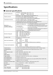
...TAP) Digital effect 2 mute: on/off, Tap delay POWER switch on each channel lits when POST EQ signal reaches the level -3 dB below maximum variable level. high speed (70°C) +48 V (balanced input) FC5 (Foot switch), RK-124 (EMX5000-12) USA and Canada:120 V AC 60 Hz, 400 W Europe: 230 V ...AC 50 Hz, 550 W Other: 240 V AC 50 Hz, 550 W EMX5000-20/EMX5000-12-Owner's Manual low speed (50°C) -
...TAP) Digital effect 2 mute: on/off, Tap delay POWER switch on each channel lits when POST EQ signal reaches the level -3 dB below maximum variable level. high speed (70°C) +48 V (balanced input) FC5 (Foot switch), RK-124 (EMX5000-12) USA and Canada:120 V AC 60 Hz, 400 W Europe: 230 V ...AC 50 Hz, 550 W Other: 240 V AC 50 Hz, 550 W EMX5000-20/EMX5000-12-Owner's Manual low speed (50°C) -

