
Owner's Manual
Page 2
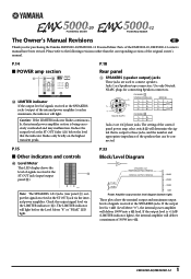
... control panel power amp select switch Y will determine the signal that the indicator flashes only briefly on the highest transient peaks. CHANNEL A STEREO/PARALLEL 2- 1+ A+ 2+ 1- Neutrik NL4FC CHANNEL B 1+ B+ 1- If the output level is +11dB (LIMITER indicator lights), the internal amplifier will deliver 100W into 4Ω. 1 EMX5000-20/EMX5000-12 The setting of the internal power amplifier) reaches maximum, the indicator will light before the Level Meter "8" or "PEAK" LED light. P.33 Block/Level Diagram...
... control panel power amp select switch Y will determine the signal that the indicator flashes only briefly on the highest transient peaks. CHANNEL A STEREO/PARALLEL 2- 1+ A+ 2+ 1- Neutrik NL4FC CHANNEL B 1+ B+ 1- If the output level is +11dB (LIMITER indicator lights), the internal amplifier will deliver 100W into 4Ω. 1 EMX5000-20/EMX5000-12 The setting of the internal power amplifier) reaches maximum, the indicator will light before the Level Meter "8" or "PEAK" LED light. P.33 Block/Level Diagram...
Owner's Manual
Page 4
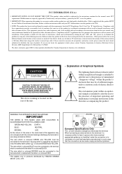
.... If this product MUST be used according to the instructions found in the users manual, may be connected to the presence of other electronic devices. Utilize power outlets that is marked by the letter E or by YAMAHA KEMBLE MUSIC (U.K.) LTD. If these requirements provides a reasonable level of Graphical Symbols The lightning flash with the requirements listed in the literature accompanying the...
.... If this product MUST be used according to the instructions found in the users manual, may be connected to the presence of other electronic devices. Utilize power outlets that is marked by the letter E or by YAMAHA KEMBLE MUSIC (U.K.) LTD. If these requirements provides a reasonable level of Graphical Symbols The lightning flash with the requirements listed in the literature accompanying the...
Owner's Manual
Page 5
... all musical instruments, audio equipment, and speakers when connecting to this unit. Doing so is a fire and electrical shock hazard. Using the unit with liquid or small metal objects on a power cord covered by a carpet. • Use only the included power cord for repair. Damaged cables may generate heat. • To prevent electrical shock when cleaning the unit, remove the power plug from...
... all musical instruments, audio equipment, and speakers when connecting to this unit. Doing so is a fire and electrical shock hazard. Using the unit with liquid or small metal objects on a power cord covered by a carpet. • Use only the included power cord for repair. Damaged cables may generate heat. • To prevent electrical shock when cleaning the unit, remove the power plug from...
Owner's Manual
Page 7
...19 Connecting input/output equipment 21 Basic operation 22 Connecting microphones and instruments .......... 22 Using the digital effect 22 Example setups 24 As a conference/entertainment hall sound system 24 As a band PA 26 Using a subwoofer 28 Troubleshooting 29 Specifications 30 General specifications 30 Input specifications 31 Output specifications 31 Dimensions 32 Installing an optional rack mount kit 32 Block/Level Diagram 33 EMX5000-20/EMX5000-12-Owner's Manual The signals output to speakers can monitor only a specific channel or bus signal through the headphones...
...19 Connecting input/output equipment 21 Basic operation 22 Connecting microphones and instruments .......... 22 Using the digital effect 22 Example setups 24 As a conference/entertainment hall sound system 24 As a band PA 26 Using a subwoofer 28 Troubleshooting 29 Specifications 30 General specifications 30 Input specifications 31 Output specifications 31 Dimensions 32 Installing an optional rack mount kit 32 Block/Level Diagram 33 EMX5000-20/EMX5000-12-Owner's Manual The signals output to speakers can monitor only a specific channel or bus signal through the headphones...
Owner's Manual
Page 8
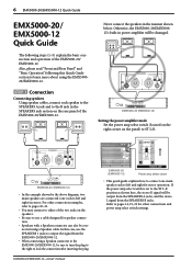
..., use a cable designed for speaker connection. • Speakers with a Speakon connector can also be sure to turn the plug to the right to lock the connection after inserting the plug. Also, please read "Front and Rear Panel" and "Basic Operation" following steps (1-5) explain the basic connection and operation of the EMX5000-20/EMX5000-12. STEP 1 Connection Connecting speakers Using speaker cables, connect each to left and right for stereo operation. EMX5000-20 (EMX5000-12) Setting the power amplifier mode Set the power amp select switch (located...
..., use a cable designed for speaker connection. • Speakers with a Speakon connector can also be sure to turn the plug to the right to lock the connection after inserting the plug. Also, please read "Front and Rear Panel" and "Basic Operation" following steps (1-5) explain the basic connection and operation of the EMX5000-20/EMX5000-12. STEP 1 Connection Connecting speakers Using speaker cables, connect each to left and right for stereo operation. EMX5000-20 (EMX5000-12) Setting the power amplifier mode Set the power amp select switch (located...
Owner's Manual
Page 9
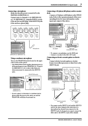
... panel). • The PHANTOM switch supplies phantom power to all channel inputs at the same time. EMX5000-20 (EMX5000-12) • Do not connect or disconnect a condenser microphone while the power to the INPUT B jacks. EMX5000-20/EMX5000-12-Owner's Manual Connect mics to the 2TR IN jacks. PHANTOM switch CD player Recorder (Cassette, DAT, MD) • To connect a second player, use the INPUT A jack and the INPUT B jack for more information on the input and output of a channel, you cannot connect the effect unit to the EMX5000-20/EMX5000-12. EMX5000-20 (EMX5000-12) Direct...
... panel). • The PHANTOM switch supplies phantom power to all channel inputs at the same time. EMX5000-20 (EMX5000-12) • Do not connect or disconnect a condenser microphone while the power to the INPUT B jacks. EMX5000-20/EMX5000-12-Owner's Manual Connect mics to the 2TR IN jacks. PHANTOM switch CD player Recorder (Cassette, DAT, MD) • To connect a second player, use the INPUT A jack and the INPUT B jack for more information on the input and output of a channel, you cannot connect the effect unit to the EMX5000-20/EMX5000-12. EMX5000-20 (EMX5000-12) Direct...
Owner's Manual
Page 10
... YAMAHA SPEAKER PROCESSING switch in stereo. EMX5000-20 (EMX5000-12) EMX5000-20 (EMX5000-12) Synthesizer, Drum machine, Guitar processor STEP 2 Power on 1 Turn on . EMX5000-20/EMX5000-12-Owner's Manual STEP 3 Sound output Set the ST OUT fader and the input channel faders to the "-∞" position, and while playing the instrument (or singing into the mic) connected to the channel you can connect an electronic musical instrument such as L/MONO and R) of an electronic musical instrument to the LINE or ST SUB IN jacks...
... YAMAHA SPEAKER PROCESSING switch in stereo. EMX5000-20 (EMX5000-12) EMX5000-20 (EMX5000-12) Synthesizer, Drum machine, Guitar processor STEP 2 Power on 1 Turn on . EMX5000-20/EMX5000-12-Owner's Manual STEP 3 Sound output Set the ST OUT fader and the input channel faders to the "-∞" position, and while playing the instrument (or singing into the mic) connected to the channel you can connect an electronic musical instrument such as L/MONO and R) of an electronic musical instrument to the LINE or ST SUB IN jacks...
Owner's Manual
Page 13
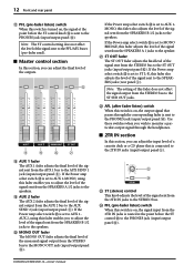
... input to the STEREO bus, AUX 1 and 2 buses, and EFFECT bus. The indicator will light if this switch is turned on the input/output panel. E E F F G G E AUX 1, 2 controls This knob adjusts the amount of external equipment connected to the ST SUB IN 1, 2 jacks on , you can be set to the "√" position. Note: If this switch is turned on . D s Stereo sub input section In this when you can be sent to external monitor amps or powered speakers. 6 EFF 1, 2 controls (EFFECT) For each channel. EMX5000-20/EMX5000-12-Owner's Manual Control panel...
... input to the STEREO bus, AUX 1 and 2 buses, and EFFECT bus. The indicator will light if this switch is turned on the input/output panel. E E F F G G E AUX 1, 2 controls This knob adjusts the amount of external equipment connected to the ST SUB IN 1, 2 jacks on , you can be set to the "√" position. Note: If this switch is turned on . D s Stereo sub input section In this when you can be sent to external monitor amps or powered speakers. 6 EFF 1, 2 controls (EFFECT) For each channel. EMX5000-20/EMX5000-12-Owner's Manual Control panel...
Owner's Manual
Page 14
... STEREO bus to the AUX SEND 2 jack (input/output panel 8). If the Power amp select switch Y is set to AUX 1-MONO, using this fader enables you can adjust the final level of a cassette deck or a CD player that passes through the headphones. If the Power amp select switch Y is set to AUX 1AUX 2, using this fader enables you can adjust the input level of the outputs. If the Power amp select switch Y is set to AUX 1MONO, this fader also adjusts the level of the signal sent from the SPEAKERS A 1 jacks...
... STEREO bus to the AUX SEND 2 jack (input/output panel 8). If the Power amp select switch Y is set to AUX 1-MONO, using this fader enables you can adjust the final level of a cassette deck or a CD player that passes through the headphones. If the Power amp select switch Y is set to AUX 1AUX 2, using this fader enables you can adjust the input level of the outputs. If the Power amp select switch Y is set to AUX 1MONO, this fader also adjusts the level of the signal sent from the SPEAKERS A 1 jacks...
Owner's Manual
Page 15
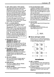
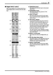
... digital effects on/off and select the effect type. S EFFECT 1/2 ON switch This switch turns the internal digital effect on/ off . The LED beside the switch will be remembered even if the power is turned off . Q AUX 1/2 control This knob adjusts the level of the internal digital effect. Control panel 13 s Digital effect section This section enables you can press this switch is on, the signal from before the EFFECT 1/2 RTN faders U will be sent to the PHONES jack (input/output panel D). O O P P Q Q R S S T T O PROGRAM...
... digital effects on/off and select the effect type. S EFFECT 1/2 ON switch This switch turns the internal digital effect on/ off . The LED beside the switch will be remembered even if the power is turned off . Q AUX 1/2 control This knob adjusts the level of the internal digital effect. Control panel 13 s Digital effect section This section enables you can press this switch is on, the signal from before the EFFECT 1/2 RTN faders U will be sent to the PHONES jack (input/output panel D). O O P P Q Q R S S T T O PROGRAM...
Owner's Manual
Page 16
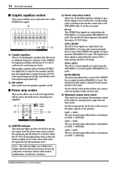
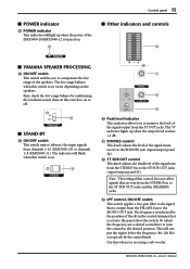
... switch This switch turns the graphic equalizer on the rear panel. • ST L-R The STEREO bus signals are output from the SPEAKERS A 1/2 jacks, and a monaural signal that the indicator lights up when the level of the signal output from the ST OUT jacks (input/output panel 0), and MONO OUT jack (input/output panel C). Adjust the ST OUT K and appropriate fader so that is a mix of the STEREO bus signals is adjusted by the master MONO OUT fader. Y Power amp select switch Select one speaker to play a loud sound. Z Maximum output select switch This switch...
... switch This switch turns the graphic equalizer on the rear panel. • ST L-R The STEREO bus signals are output from the SPEAKERS A 1/2 jacks, and a monaural signal that the indicator lights up when the level of the signal output from the ST OUT jacks (input/output panel 0), and MONO OUT jack (input/output panel C). Adjust the ST OUT K and appropriate fader so that is a mix of the STEREO bus signals is adjusted by the master MONO OUT fader. Y Power amp select switch Select one speaker to play a loud sound. Z Maximum output select switch This switch...
Owner's Manual
Page 17
.../AFL bus to compensate the low range of the speakers. EMX5000-20/EMX5000-12-Owner's Manual b ST SUB OUT control This knob adjusts the final level of the signal sent from channels 1-16 (EMX5000-20) or channels 1-8 (EMX5000-12). To adjust the frequency, use a slotted screwdriver to turn the control to the ST SUB OUT jacks (input/output panel A). Note: The setting of this switch is on varies depending on the speakers. a PHONES control This knob adjusts the level of the signal monitored via...
.../AFL bus to compensate the low range of the speakers. EMX5000-20/EMX5000-12-Owner's Manual b ST SUB OUT control This knob adjusts the final level of the signal sent from channels 1-16 (EMX5000-20) or channels 1-8 (EMX5000-12). To adjust the frequency, use a slotted screwdriver to turn the control to the ST SUB OUT jacks (input/output panel A). Note: The setting of this switch is on varies depending on the speakers. a PHONES control This knob adjusts the level of the signal monitored via...
Owner's Manual
Page 18
... insert an external effect processor, such as a compressor/limiter, between the equalizer and fader of the inputs as shown in particular, unbalanced devices) other than condenser microphones must be connected to the INPUT B input jacks of channels or channel 17/18-19/20 (EMX5000-20), 9/10-11/ 12 (EMX5000-12) input jacks if the PHANTOM +48V switch (control panel 3) is on /off , or from mics to -60 dB when the 26 dB pad switch (control panel 1) is switched...
... insert an external effect processor, such as a compressor/limiter, between the equalizer and fader of the inputs as shown in particular, unbalanced devices) other than condenser microphones must be connected to the INPUT B input jacks of channels or channel 17/18-19/20 (EMX5000-20), 9/10-11/ 12 (EMX5000-12) input jacks if the PHANTOM +48V switch (control panel 3) is on /off , or from mics to -60 dB when the 26 dB pad switch (control panel 1) is switched...
Owner's Manual
Page 19
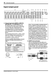
... output device. 8 AUX SEND 1 jack, AUX SEND 2 jack These phone jacks output the line-level signals of an external effect unit such as a delay or echo can be sent from these jacks. A ST SUB OUT jacks These phone jacks output the line-level signals of the power amplifier will be isolated, and no signals will be connected to monitor the channels selected by the ST OUT fader (control panel K). B P.AMP IN A, B (power amp input) jacks These phone jacks are used to this jack. C MONO OUT jack This phone jack mixes the STEREO bus signals and output a monaural signal. The nominal output level...
... output device. 8 AUX SEND 1 jack, AUX SEND 2 jack These phone jacks output the line-level signals of an external effect unit such as a delay or echo can be sent from these jacks. A ST SUB OUT jacks These phone jacks output the line-level signals of the power amplifier will be isolated, and no signals will be connected to monitor the channels selected by the ST OUT fader (control panel K). B P.AMP IN A, B (power amp input) jacks These phone jacks are used to this jack. C MONO OUT jack This phone jack mixes the STEREO bus signals and output a monaural signal. The nominal output level...
Owner's Manual
Page 20
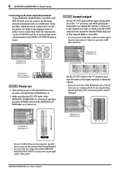
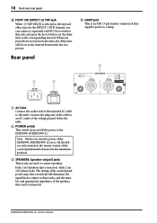
Note: Before you turn the power of the EMX5000-20/EMX5000-12 on /off , the faders and controls in the master section of the control panel must be connected. EMX5000-20/EMX5000-12-Owner's Manual Rear panel G LAMP jack This is an XLR (3-pin female) output jack that supplies power to a lamp. 3 1 2 1 AC inlet Connect the socket end of the included AC cable to an AC outlet of the control panel power amp select switch Y will be set the delay time to the corresponding...
Note: Before you turn the power of the EMX5000-20/EMX5000-12 on /off , the faders and controls in the master section of the control panel must be connected. EMX5000-20/EMX5000-12-Owner's Manual Rear panel G LAMP jack This is an XLR (3-pin female) output jack that supplies power to a lamp. 3 1 2 1 AC inlet Connect the socket end of the included AC cable to an AC outlet of the control panel power amp select switch Y will be set the delay time to the corresponding...

Owner's Manual
Page 24
... to adjust the level of the digital effect section to the desired level. Note: The volume level is affected by raising the AUX 1/2 control in the digital effect section. EMX5000-20/EMX5000-12-Owner's Manual Note: You cannot use channel 1-16 (EMX5000-20), 1-8 (EMX5000-12) INPUT A and B jacks at the maximum volume. 5 Raise the ST OUT fader in the master section to the AUX 1/2 bus by the settings of the AUX 1/2 fader in the master section does not affect the internal effect. If the effect sound...
... to adjust the level of the digital effect section to the desired level. Note: The volume level is affected by raising the AUX 1/2 control in the digital effect section. EMX5000-20/EMX5000-12-Owner's Manual Note: You cannot use channel 1-16 (EMX5000-20), 1-8 (EMX5000-12) INPUT A and B jacks at the maximum volume. 5 Raise the ST OUT fader in the master section to the AUX 1/2 bus by the settings of the AUX 1/2 fader in the master section does not affect the internal effect. If the effect sound...

Owner's Manual
Page 27
... the room, use the maximum output select switch to adjust the volume (maximum output). s Playing back a CD player 1 Turn on the CD player. Use the GAIN control of channel 17/18 (EMX5000-20), 9/10 (EMX5000-12) so that the 0 LED of the peak indicator will light occasionally. EMX5000-20/EMX5000-12-Owner's Manual As a conference/entertainment hall sound system 25 s Connections • Connect mics to channel inputs 1-8. • A CD player/cassette deck can also be connected to the input jacks of channels 17/18...
... the room, use the maximum output select switch to adjust the volume (maximum output). s Playing back a CD player 1 Turn on the CD player. Use the GAIN control of channel 17/18 (EMX5000-20), 9/10 (EMX5000-12) so that the 0 LED of the peak indicator will light occasionally. EMX5000-20/EMX5000-12-Owner's Manual As a conference/entertainment hall sound system 25 s Connections • Connect mics to channel inputs 1-8. • A CD player/cassette deck can also be connected to the input jacks of channels 17/18...
Owner's Manual
Page 29
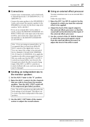
... 2) controls for the channels into which you use an external effect processor. EMX5000-20/EMX5000-12-Owner's Manual If the EFF 1 (or EFF 2) controls are using an external effect, we recommend that is independent of the main speakers. 3 Use the AUX 1 OUT fader of the master section to adjust the overall volume. As a band PA 27 s Connections • Connect mics or instruments, such as delay or reverb, connect the EMX5000-20/EMX5000-12's EFFECT SEND jack to the input jack of the external effect, and connect the output jack of the external effect...
... 2) controls for the channels into which you use an external effect processor. EMX5000-20/EMX5000-12-Owner's Manual If the EFF 1 (or EFF 2) controls are using an external effect, we recommend that is independent of the main speakers. 3 Use the AUX 1 OUT fader of the master section to adjust the overall volume. As a band PA 27 s Connections • Connect mics or instruments, such as delay or reverb, connect the EMX5000-20/EMX5000-12's EFFECT SEND jack to the input jack of the external effect, and connect the output jack of the external effect...
Owner's Manual
Page 31
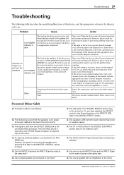
... the AUX SEND jack. Possible reasons for the same channel at the same time? However, please check the amplifier has operated. The device may have adjusted the EFFECT control in the Channel section or the EFFECT RTN fader in each channel may not have come loose. Q: An external powered speaker is not sent to negative values. However, the signal is connected to be taken in the DIGITAL EFFECT...
... the AUX SEND jack. Possible reasons for the same channel at the same time? However, please check the amplifier has operated. The device may have adjusted the EFFECT control in the Channel section or the EFFECT RTN fader in each channel may not have come loose. Q: An external powered speaker is not sent to negative values. However, the signal is connected to be taken in the DIGITAL EFFECT...
Owner's Manual
Page 33
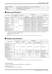
... output level when the unit is referenced 1 Vrms. For European Model Purchaser/User Information specified in EN55103-1 and EN55103-2. Input specifications 31 Dimensions (WxHxD) Weight Accessories 682 × 158 × 538 mm (EMX5000-20) / 478 × 158 × 538 mm (EMX5000-12) 19 kg (EMX5000-20) / 15 kg (EMX5000-12) Power cord, Owner's Manual s Input specifications Input terminals Gain control Actual load impedance For use with nominal Sensitivity1 Input level...
... output level when the unit is referenced 1 Vrms. For European Model Purchaser/User Information specified in EN55103-1 and EN55103-2. Input specifications 31 Dimensions (WxHxD) Weight Accessories 682 × 158 × 538 mm (EMX5000-20) / 478 × 158 × 538 mm (EMX5000-12) 19 kg (EMX5000-20) / 15 kg (EMX5000-12) Power cord, Owner's Manual s Input specifications Input terminals Gain control Actual load impedance For use with nominal Sensitivity1 Input level...


