
Owner's Manual
Page 1
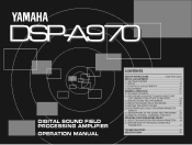
DSP-A970 DIGITAL SOUND FIELD PROCESSING AMPLIFIER OPERATION MANUAL CONTENTS SAFETY INSTRUCTIONS Inside Front Cover SETUP & ADJUSTMENT 3 1-1.GETTING STARTED 3 1-2.SETUP 10 1-3.CONTROLS & ADJUSTMENTS 18 1-4.ADJUSTMENT 22 GENERAL OPERATION 27 2-1.PLAYING A SOURCE 27 2-2.RECORDING A SOURCE TO AUDIO/VIDEO TAPE (OR DUBBING FROM A TAPE TO ANOTHER 28 2-3.DIGITAL SOUND FIELD PROGRAMS 30 2-4.SELECTING SOUND FIELD PROGRAMS 30 2-5.MUTING THE EFFECT SOUND 31 2-6.SUPERIMPOSED VIDEO PROGRAM/PARAMETER DISPLAY 31 2-7.DESCRIPTIONS OF THE SOUND FIELD PROGRAMS .... 32 2-8.REMOTE CONTROL "LEARNING" ...
DSP-A970 DIGITAL SOUND FIELD PROCESSING AMPLIFIER OPERATION MANUAL CONTENTS SAFETY INSTRUCTIONS Inside Front Cover SETUP & ADJUSTMENT 3 1-1.GETTING STARTED 3 1-2.SETUP 10 1-3.CONTROLS & ADJUSTMENTS 18 1-4.ADJUSTMENT 22 GENERAL OPERATION 27 2-1.PLAYING A SOURCE 27 2-2.RECORDING A SOURCE TO AUDIO/VIDEO TAPE (OR DUBBING FROM A TAPE TO ANOTHER 28 2-3.DIGITAL SOUND FIELD PROGRAMS 30 2-4.SELECTING SOUND FIELD PROGRAMS 30 2-5.MUTING THE EFFECT SOUND 31 2-6.SUPERIMPOSED VIDEO PROGRAM/PARAMETER DISPLAY 31 2-7.DESCRIPTIONS OF THE SOUND FIELD PROGRAMS .... 32 2-8.REMOTE CONTROL "LEARNING" ...
Owner's Manual
Page 2
...Power Sources - PRECAUTIONS & SAFETY INSTRUCTIONS CAUTION RISK OF ELECTRIC SHOCK DO NOT OPEN CAUTION: TO REDUCE THE RISK OF ELECTRIC SHOCK, DO NOT REMOVE COVER (OR BACK), NO USER-SERVICEABLE PARTS INSIDE, REFER SERVICING TO QUALIFIED SERVICE PERSONNEL. • Explanation of Graphical Symbols The lightning flash...unit. 11 Power-Cord Protection - The unit should not be used only with a cart or stand that may impede the flow of the type described in the operating instructions. The unit should be connected to service the unit beyond those means described in the operating instructions or as...
...Power Sources - PRECAUTIONS & SAFETY INSTRUCTIONS CAUTION RISK OF ELECTRIC SHOCK DO NOT OPEN CAUTION: TO REDUCE THE RISK OF ELECTRIC SHOCK, DO NOT REMOVE COVER (OR BACK), NO USER-SERVICEABLE PARTS INSIDE, REFER SERVICING TO QUALIFIED SERVICE PERSONNEL. • Explanation of Graphical Symbols The lightning flash...unit. 11 Power-Cord Protection - The unit should not be used only with a cart or stand that may impede the flow of the type described in the operating instructions. The unit should be connected to service the unit beyond those means described in the operating instructions or as...
Owner's Manual
Page 3
... the users manual, may overheat, possibly causing damage. 4 Never open the cabinet. This product, when installed as indicated in the instructions contained in this manual carefully. Avoid sources of radio or TV interference, relocate/reorient the antenna. Follow all installations. Utilize power outlets that lets the sound come through loud and clear without affecting your unit is 300 ohm ribbon lead, change the...
... the users manual, may overheat, possibly causing damage. 4 Never open the cabinet. This product, when installed as indicated in the instructions contained in this manual carefully. Avoid sources of radio or TV interference, relocate/reorient the antenna. Follow all installations. Utilize power outlets that lets the sound come through loud and clear without affecting your unit is 300 ohm ribbon lead, change the...

Owner's Manual
Page 4
... this manual carefully when setting up the system and trying out its many capabilities. Congratulations! Seven built-in Dolby Pro Logic Surround Decoder. Rather than tell you about the wonders of digital sound field processing, however, let's get incredible realism from Dolby-Surround encoded video sources using the built-in channels of amplification on the DSP-A970 mean that no additional amplifiers are the proud owner of a Yamaha Digital Sound...
... this manual carefully when setting up the system and trying out its many capabilities. Congratulations! Seven built-in Dolby Pro Logic Surround Decoder. Rather than tell you about the wonders of digital sound field processing, however, let's get incredible realism from Dolby-Surround encoded video sources using the built-in channels of amplification on the DSP-A970 mean that no additional amplifiers are the proud owner of a Yamaha Digital Sound...
Owner's Manual
Page 7
... YAMAHA directional enhancement (DIR. This always assures you the best performance without manual adjustment. Canadian numbers 1,004,603 and 1,037,877. The YAMAHA "CINEMA DSP" logo indicates these programs created by the combination of Dolby Pro Logic. This circuit is more of the following patents: U.S. Dolby Pro Logic Surround provides a true center channel, so that positioning of sounds around the room is available on the screen while experiencing good stereo...
... YAMAHA directional enhancement (DIR. This always assures you the best performance without manual adjustment. Canadian numbers 1,004,603 and 1,037,877. The YAMAHA "CINEMA DSP" logo indicates these programs created by the combination of Dolby Pro Logic. This circuit is more of the following patents: U.S. Dolby Pro Logic Surround provides a true center channel, so that positioning of sounds around the room is available on the screen while experiencing good stereo...

Owner's Manual
Page 8
... of a Yamaha Active Servo Processing Subwoofer System, which has its own built-in power amp. 6 We therefore recommend that you want to upgrade the Audio/Video home theater system, it . Therefore, if you use the center speaker unit. If for dialog, when using Dolby Pro Logic Surround decoding. Setting Up Your Speaker System This unit has been designed to provide the best sound field quality with a full seven-speaker system setup, using two...
... of a Yamaha Active Servo Processing Subwoofer System, which has its own built-in power amp. 6 We therefore recommend that you want to upgrade the Audio/Video home theater system, it . Therefore, if you use the center speaker unit. If for dialog, when using Dolby Pro Logic Surround decoding. Setting Up Your Speaker System This unit has been designed to provide the best sound field quality with a full seven-speaker system setup, using two...
Owner's Manual
Page 13
... ground wire of an external stereo power amplifier driving the rear effect speakers. 5 Main Speaker Terminals When using the built-in amplifier is used for Video Source Equipment) Connect the audio and video inputs and/or outputs of an external stereo power amplifier driving the front effect speakers. 4 Rear Effect Out Jacks Rear-channel line output. English 1 Audio Signal Connection Jacks (for Audio Source Equipment) Connect the inputs and/or outputs of your audio equipment. 2 Audio/Video Signal Connection Jacks (for higher resolution and improved picture quality if your VCR, monitor...
... ground wire of an external stereo power amplifier driving the rear effect speakers. 5 Main Speaker Terminals When using the built-in amplifier is used for Video Source Equipment) Connect the audio and video inputs and/or outputs of an external stereo power amplifier driving the front effect speakers. 4 Rear Effect Out Jacks Rear-channel line output. English 1 Audio Signal Connection Jacks (for Audio Source Equipment) Connect the inputs and/or outputs of your audio equipment. 2 Audio/Video Signal Connection Jacks (for higher resolution and improved picture quality if your VCR, monitor...
Owner's Manual
Page 14
... you connect cables. F Switched AC Outlets You may plug other plugs for 7 or 6 speaker driving. This is off and no output will be turned off . NOTE: If an external power amplifier is connected to the front effect or rear effect output jacks, the corresponding internal amplifier will be sure that the polarity is set the FRONT MIX switch to always use a speaker cable that the FRONT MIX switch is correct. With speaker connections...
... you connect cables. F Switched AC Outlets You may plug other plugs for 7 or 6 speaker driving. This is off and no output will be turned off . NOTE: If an external power amplifier is connected to the front effect or rear effect output jacks, the corresponding internal amplifier will be sure that the polarity is set the FRONT MIX switch to always use a speaker cable that the FRONT MIX switch is correct. With speaker connections...

Owner's Manual
Page 16
... S VIDEO MONITOR OUT or VIDEO MONITOR OUT jack in this unit, signals of screen display information are output from your video cassette recorder, video disc player, etc. to the VIDEO jacks of your monitor. Video disc player NOTE: If your unit is set to the composite video input of this unit, and connect this unit's S VIDEO MONITOR OUT jack to their respective output jacks independently. and your monitor are output from either S VIDEO or VIDEO input jacks of your monitor. Video cassette recorder 1 14 TV/Satellite tuner Video...
... S VIDEO MONITOR OUT or VIDEO MONITOR OUT jack in this unit, signals of screen display information are output from your video cassette recorder, video disc player, etc. to the VIDEO jacks of your monitor. Video disc player NOTE: If your unit is set to the composite video input of this unit, and connect this unit's S VIDEO MONITOR OUT jack to their respective output jacks independently. and your monitor are output from either S VIDEO or VIDEO input jacks of your monitor. Video cassette recorder 1 14 TV/Satellite tuner Video...

Owner's Manual
Page 19
... main and center channels. CONNECTING SPEAKER SYSTEMS Connect the SPEAKERS terminals to the subwoofer. If these wires are in the same unit. NOTE: Banana Plug connections are observed. markings are also possible (except for Europe model). With some subwoofers, including the Yamaha Active Servo Processing Subwoofer System, the amplifier and subwoofer are reversed, the sound will lack bass. This unit provides a line-level subwoofer output, which contains only the frequencies under 200...
... main and center channels. CONNECTING SPEAKER SYSTEMS Connect the SPEAKERS terminals to the subwoofer. If these wires are in the same unit. NOTE: Banana Plug connections are observed. markings are also possible (except for Europe model). With some subwoofers, including the Yamaha Active Servo Processing Subwoofer System, the amplifier and subwoofer are reversed, the sound will lack bass. This unit provides a line-level subwoofer output, which contains only the frequencies under 200...

Owner's Manual
Page 20
1-3. CONTROLS & ADJUSTMENTS FRONT PANEL (General Model) 1 Power Switch * STANDBY Mode (Europe model only) While the power is on, pressing the POWER key on the remote control unit switches the unit to the STANDBY mode. (In this mode, the indicator is half illuminated.) 2 Remote control sensor Signals from the remote control unit are received here. 3 Pro Logic Decoder Indicator Illuminates while the built-in Dolby Pro Logic Surround Decoder is being activated. 4 Sound Field Processor Indicator Illuminates while the built-in Sound Field Processor is being activated. 18
1-3. CONTROLS & ADJUSTMENTS FRONT PANEL (General Model) 1 Power Switch * STANDBY Mode (Europe model only) While the power is on, pressing the POWER key on the remote control unit switches the unit to the STANDBY mode. (In this mode, the indicator is half illuminated.) 2 Remote control sensor Signals from the remote control unit are received here. 3 Pro Logic Decoder Indicator Illuminates while the built-in Dolby Pro Logic Surround Decoder is being activated. 4 Sound Field Processor Indicator Illuminates while the built-in Sound Field Processor is being activated. 18

Owner's Manual
Page 21
.... 0 Bass and Treble Controls Adjust the sound to and/or watch in headphones here for room acoustics. The source connected to disable output from the center and effect speakers. 8 Master Volume Control Simultaneously controls signal level at all outputs: front effect, main, rear effect, center, and subwoofer. (This does not affect TAPE REC OUT level.) 9 Phones Jack Plug in the ᮣ or ᮤ direction. Otherwise the main channels only will be heard along with the input selector switches...
.... 0 Bass and Treble Controls Adjust the sound to and/or watch in headphones here for room acoustics. The source connected to disable output from the center and effect speakers. 8 Master Volume Control Simultaneously controls signal level at all outputs: front effect, main, rear effect, center, and subwoofer. (This does not affect TAPE REC OUT level.) 9 Phones Jack Plug in the ᮣ or ᮤ direction. Otherwise the main channels only will be heard along with the input selector switches...

Owner's Manual
Page 22
..., and rear effect speakers in turn for easy comparison of level settings. 7 Front Level +/- Keys Increase (+) or decrease (-) the volume level of YAMAHA Preset Code.) 3 Power Key Turns this unit and Yamaha equipments. When the 1/2 Switch is the abbreviation of the front effect speakers. Set to indicate that a control signal has been sent to your Yamaha CD player and LD player. REMOTE CONTROL UNIT 20 1 Transmit/Learn Indicator In Learn mode, lights to USER for using learned key functions.
..., and rear effect speakers in turn for easy comparison of level settings. 7 Front Level +/- Keys Increase (+) or decrease (-) the volume level of YAMAHA Preset Code.) 3 Power Key Turns this unit and Yamaha equipments. When the 1/2 Switch is the abbreviation of the front effect speakers. Set to indicate that a control signal has been sent to your Yamaha CD player and LD player. REMOTE CONTROL UNIT 20 1 Transmit/Learn Indicator In Learn mode, lights to USER for using learned key functions.
Owner's Manual
Page 23
... Button Used in the SET/MENU mode. D Parameter Select Keys Select DSP program parameters, or titles of the rear effect speakers. 0 Reset Button Press this key again. When set to USER or LEARN, this switch selects page 1 or 2 for learning other remote controller's functions only. L Tape Deck Function Keys Operate Yamaha tape deck functions. Microcomputer "reset" is necessary when the remote control freezes. * Pressing the RESET button will set to the PARAMETER position, the Parameter Select Keys and Parameter +/- H Master Volume +/- K Tuner Function Keys Operate Yamaha...
... Button Used in the SET/MENU mode. D Parameter Select Keys Select DSP program parameters, or titles of the rear effect speakers. 0 Reset Button Press this key again. When set to USER or LEARN, this switch selects page 1 or 2 for learning other remote controller's functions only. L Tape Deck Function Keys Operate Yamaha tape deck functions. Microcomputer "reset" is necessary when the remote control freezes. * Pressing the RESET button will set to the PARAMETER position, the Parameter Select Keys and Parameter +/- H Master Volume +/- K Tuner Function Keys Operate Yamaha...

Owner's Manual
Page 24
... change any other volume settings in the display panel to adjust listening volume. 1-4. Depress the TEST switch on external power amplifiers may decrease the main speaker volume level by using the CENTER and REAR LEVEL +/- appears in the system. 22 Adjust the front level by setting the MAIN LEVEL switch on the remote control so that the sound coming from the left main speaker, center speaker(s), right main speaker and rear effect speakers in the display panel. If there is the same as that "TEST DOLBY...
... change any other volume settings in the display panel to adjust listening volume. 1-4. Depress the TEST switch on external power amplifiers may decrease the main speaker volume level by using the CENTER and REAR LEVEL +/- appears in the system. 22 Adjust the front level by setting the MAIN LEVEL switch on the remote control so that the sound coming from the left main speaker, center speaker(s), right main speaker and rear effect speakers in the display panel. If there is the same as that "TEST DOLBY...

Owner's Manual
Page 28
...; TEST switch 5. The sound level of each input source should be locked by this operation. A program number whose parameters has been changed . To adjust the input level, either press the INPUT TRIM control on this unit can be the same as that a DSP program (except CHURCH) has two sub-programs; INPUT LVL TRIM" in 2 dB steps. 3. key to +6 dB in step 2 on a DSP program. When initialized, the "*" mark will disappear. 4. The following functions...
...; TEST switch 5. The sound level of each input source should be locked by this operation. A program number whose parameters has been changed . To adjust the input level, either press the INPUT TRIM control on this unit can be the same as that a DSP program (except CHURCH) has two sub-programs; INPUT LVL TRIM" in 2 dB steps. 3. key to +6 dB in step 2 on a DSP program. When initialized, the "*" mark will disappear. 4. The following functions...

Owner's Manual
Page 30
... corresponding to the selected source to be gained after the REC OUT switch is pressed, select the "SOURCE" position with the input selector switch (so that "REC OUT..." Front panel 5. Play the source. 6. Set the tape deck or VCR used for the method of input source selection.) Front panel Remote control 2. RECORDING A SOURCE TO AUDIO/VIDEO TAPE (OR DUBBING FROM A TAPE TO ANOTHER) To record an input source to the recording mode. * Adjust the recording level on the display and the monitor screen).
... corresponding to the selected source to be gained after the REC OUT switch is pressed, select the "SOURCE" position with the input selector switch (so that "REC OUT..." Front panel 5. Play the source. 6. Set the tape deck or VCR used for the method of input source selection.) Front panel Remote control 2. RECORDING A SOURCE TO AUDIO/VIDEO TAPE (OR DUBBING FROM A TAPE TO ANOTHER) To record an input source to the recording mode. * Adjust the recording level on the display and the monitor screen).

Owner's Manual
Page 31
... tape deck or VCR used for recording to be recorded by selecting it with an input selector switch. 29 Press the REC OUT switch ( so that the indicator corresponding to the selected source to be recorded stops flashing). * The same result will be gained after the REC OUT switch is pressed, select the source to the recording mode. * Adjust the recording level on the display and the monitor screen...
... tape deck or VCR used for recording to be recorded by selecting it with an input selector switch. 29 Press the REC OUT switch ( so that the indicator corresponding to the selected source to be recorded stops flashing). * The same result will be gained after the REC OUT switch is pressed, select the source to the recording mode. * Adjust the recording level on the display and the monitor screen...

Owner's Manual
Page 32
... you can be a case that can record only a S video (or only a composite video) signal on your second VCR. Set the PARAMETER/SET MENU switch on the remote control to record from around the world, and 6 programs for digital sound field processing, 6 from actual acoustic environments from records, compact discs, radio, etc. NOTE: Adjusting the MASTER VOLUME, BASS, TREBLE controls, etc., or selecting a sound field program has no effect on the material being dubbed, there...
... you can be a case that can record only a S video (or only a composite video) signal on your second VCR. Set the PARAMETER/SET MENU switch on the remote control to record from around the world, and 6 programs for digital sound field processing, 6 from actual acoustic environments from records, compact discs, radio, etc. NOTE: Adjusting the MASTER VOLUME, BASS, TREBLE controls, etc., or selecting a sound field program has no effect on the material being dubbed, there...
Owner's Manual
Page 46
... connections. Set the FRONT MIX switch to turn on will function from a maximum range of the main unit. Turning the unit off . Erase unnecessary functions. TROUBLESHOOTING PROBLEM Power does not come on a tape deck connected to "ON". The sound field cannot be changed. The TRANSMIT/LEARN indicator blinks twice when learning a function. Bad cable connection. Bad or incorrect input connection. Incorrect input source selection. The protection circuit has activated because of the main unit. Direct sunlight or lighting...
... connections. Set the FRONT MIX switch to turn on will function from a maximum range of the main unit. Turning the unit off . Erase unnecessary functions. TROUBLESHOOTING PROBLEM Power does not come on a tape deck connected to "ON". The sound field cannot be changed. The TRANSMIT/LEARN indicator blinks twice when learning a function. Bad cable connection. Bad or incorrect input connection. Incorrect input source selection. The protection circuit has activated because of the main unit. Direct sunlight or lighting...


