
Owner's Manual
Page 3
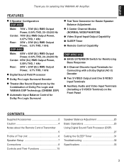
...,000 Hz Center: 70W (8Ω) RMS Output Power, 0.07% THD, 1 kHz Rear: 35W + 35W (8Ω) RMS Output Power, 0.3% THD, 1 kHz DSP-A492 Main: 65W + 65W (8Ω) RMS Output Power, 0.04% THD, 20-20,000 Hz Center: 65W (8Ω) RMS Output Power, 0.09% THD, 1 ...Channel Modes (NORMAL/WIDE/PHANTOM) q Video Signal Input/Output Capability q SLEEP Timer q Remote Control Capability DSP-A592 only q BASS EXTENSION Switch for Reinforcing Bass Response q 6-Channel Discrete Input Terminals for selecting this YAMAHA AV Amplifier. English Thank you for Connecting with a Dolby Digital (AC-3) Decoder q ...
...,000 Hz Center: 70W (8Ω) RMS Output Power, 0.07% THD, 1 kHz Rear: 35W + 35W (8Ω) RMS Output Power, 0.3% THD, 1 kHz DSP-A492 Main: 65W + 65W (8Ω) RMS Output Power, 0.04% THD, 20-20,000 Hz Center: 65W (8Ω) RMS Output Power, 0.09% THD, 1 ...Channel Modes (NORMAL/WIDE/PHANTOM) q Video Signal Input/Output Capability q SLEEP Timer q Remote Control Capability DSP-A592 only q BASS EXTENSION Switch for Reinforcing Bass Response q 6-Channel Discrete Input Terminals for selecting this YAMAHA AV Amplifier. English Thank you for Connecting with a Dolby Digital (AC-3) Decoder q ...

Owner's Manual
Page 5
...UM-3 batteries for an extended period of time. Avoid touching the leaked material or letting it might cause the remote control transmitter not to work correctly. In this case, reposition the main unit to the main unit, the batteries ... Notes q There should be no large obstacles between the remote control transmitter and the main unit. Clean the battery compartment thoroughly before installing new batteries. English NOTES ABOUT THE REMOTE CONTROL TRANSMITTER Battery installation Remote control transmitter operation range 2 1 3 Remote control sensor l6 20 28 l2 8 40 4 60 2 ...
...UM-3 batteries for an extended period of time. Avoid touching the leaked material or letting it might cause the remote control transmitter not to work correctly. In this case, reposition the main unit to the main unit, the batteries ... Notes q There should be no large obstacles between the remote control transmitter and the main unit. Clean the battery compartment thoroughly before installing new batteries. English NOTES ABOUT THE REMOTE CONTROL TRANSMITTER Battery installation Remote control transmitter operation range 2 1 3 Remote control sensor l6 20 28 l2 8 40 4 60 2 ...

Owner's Manual
Page 9
... models 2 SWITCHED OUTLETS (U.K. The maximum power (total power consumption of the turntable to the SWITCHED AC OUTLET(S) is 100 watts. English DSP-A492 Turntable Monitor TV Video cassette recorder TV/Satellite tuner OUTPUT GND VIDEO IN VIDEO OUT AUDIO OUT VIDEO IN AUDIO IN VIDEO OUT AUDIO OUT.... model 1 SWITCHED OUTLET Use these to connect the power cords from your components to this unit's POWER switch or the provided remote control transmitter's POWER key. SWITCHED SPEAKAERCSOUTLETS To AC outlet l LINE OUT LINE IN VIDEO OUT AUDIO OUT OUTPUT OUTPUT Tape deck, MD recorder, ...
... models 2 SWITCHED OUTLETS (U.K. The maximum power (total power consumption of the turntable to the SWITCHED AC OUTLET(S) is 100 watts. English DSP-A492 Turntable Monitor TV Video cassette recorder TV/Satellite tuner OUTPUT GND VIDEO IN VIDEO OUT AUDIO OUT VIDEO IN AUDIO IN VIDEO OUT AUDIO OUT.... model 1 SWITCHED OUTLET Use these to connect the power cords from your components to this unit's POWER switch or the provided remote control transmitter's POWER key. SWITCHED SPEAKAERCSOUTLETS To AC outlet l LINE OUT LINE IN VIDEO OUT AUDIO OUT OUTPUT OUTPUT Tape deck, MD recorder, ...
Owner's Manual
Page 14
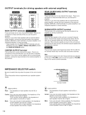
...must be 8Ω or higher. However, if you drive main speakers with external amplifiers) DSP-A592 MAIN CENTER REAR (SURROUND) DSP-A492 OUTPUT CENTER SUB WOOFER OUTPUT SUB WOOFER MAIN OUTPUT terminals DSP-A592 only These terminals are for main channel line output. Note Output level of signals from...these terminals. * Output signals from the MAIN OUTPUT terminals only are affected by the use of VOLUME control on the front panel or VOLUME keys on the remote control transmitter. DSP-A592 When the input signals to this terminal when you use one center speaker, the impedance of the ...
...must be 8Ω or higher. However, if you drive main speakers with external amplifiers) DSP-A592 MAIN CENTER REAR (SURROUND) DSP-A492 OUTPUT CENTER SUB WOOFER OUTPUT SUB WOOFER MAIN OUTPUT terminals DSP-A592 only These terminals are for main channel line output. Note Output level of signals from...these terminals. * Output signals from the MAIN OUTPUT terminals only are affected by the use of VOLUME control on the front panel or VOLUME keys on the remote control transmitter. DSP-A592 When the input signals to this terminal when you use one center speaker, the impedance of the ...
Owner's Manual
Page 16
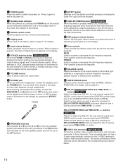
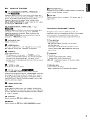
... has a S video output terminal, connect it again to switch the power off the digital sound field processor (so that no DSP program name is illuminated. 3 Remote control sensor Receives signals from the main speakers. In this mode, this button switches the input signals between 2 channel stereo signals and ... level (REAR), center channel output level (CENTER) and the output level to page 21.) F DELAY/CENTER/REAR/SWFR and TIME/LEVEL +/- buttons DSP-A492 Adjust the delay time (DELAY), the rear channel output level (REAR) and the center channel output level (CENTER). When a button is pressed, ...
... has a S video output terminal, connect it again to switch the power off the digital sound field processor (so that no DSP program name is illuminated. 3 Remote control sensor Receives signals from the main speakers. In this mode, this button switches the input signals between 2 channel stereo signals and ... level (REAR), center channel output level (CENTER) and the output level to page 21.) F DELAY/CENTER/REAR/SWFR and TIME/LEVEL +/- buttons DSP-A492 Adjust the delay time (DELAY), the rear channel output level (REAR) and the center channel output level (CENTER). When a button is pressed, ...
Owner's Manual
Page 18
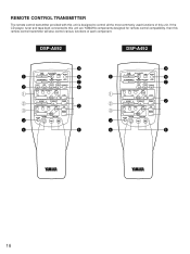
.../PAUSE PLAY A/B TAPE - DSP-A592 DSP-A492 1 2 1 2 3 3 4 - + TIME/ LEVEL DELAY/CENTER /REAR/SWFR TEST EFFECT PROGRAM PROLOGIC ENHANCED ON/OFF V-AUX VCR TV/DBS DVD/LD 2CH/6CH DIR A DIR B REC/PAUSE PLAY A/B TAPE - REMOTE CONTROL TRANSMITTER The remote control transmitter provided with this unit is designed to this unit are YAMAHA components designed for remote control compatibility, then this...
.../PAUSE PLAY A/B TAPE - DSP-A592 DSP-A492 1 2 1 2 3 3 4 - + TIME/ LEVEL DELAY/CENTER /REAR/SWFR TEST EFFECT PROGRAM PROLOGIC ENHANCED ON/OFF V-AUX VCR TV/DBS DVD/LD 2CH/6CH DIR A DIR B REC/PAUSE PLAY A/B TAPE - REMOTE CONTROL TRANSMITTER The remote control transmitter provided with this unit is designed to this unit are YAMAHA components designed for remote control compatibility, then this...
Owner's Manual
Page 19
keys DSP-A492 Adjust the delay time (DELAY), the rear channel output level (REAR) and the center channel ..., and to set the SLEEP time. (See page 31 for details.) 4 POWER key Turns the power on the remote control transmitter switches the unit from the unit connected to adjust by pressing the DELAY/CENTER/REAR/SWFR key and adjust its... to page 20-22.) For Other Component Control Identify the remote control transmitter keys with automatic reverse function, pressing DIR A will be the same. keys Turns the volume level up/down. 6 2CH/6CH selector key DSP-A592 only When the TV/DBS or DVD...
keys DSP-A492 Adjust the delay time (DELAY), the rear channel output level (REAR) and the center channel ..., and to set the SLEEP time. (See page 31 for details.) 4 POWER key Turns the power on the remote control transmitter switches the unit from the unit connected to adjust by pressing the DELAY/CENTER/REAR/SWFR key and adjust its... to page 20-22.) For Other Component Control Identify the remote control transmitter keys with automatic reverse function, pressing DIR A will be the same. keys Turns the volume level up/down. 6 2CH/6CH selector key DSP-A592 only When the TV/DBS or DVD...
Owner's Manual
Page 20
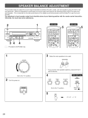
...at the listening position will be the same from each speaker output level should be done at your listening position with the remote control transmitter. The adjustment of the digital sound field processor and the Dolby Pro Logic Surround decoder. Otherwise, the result may ... 20 POWER 3 Select the main speakers to the "∞" position. 2 Turn the power on. PRESET + A/B/C/D/E TUNER DISC PLAY CD PHONO POWER SLEEP VOLUME 5 DSP-A492 - + TIME/ LEVEL DELAY/CENTER /REAR TEST EFFECT PROGRAM PROLOGIC ENHANCED ON/OFF VCR TV/DBS DVD/LD DIR A DIR B REC/PAUSE PLAY A/B TAPE - PRESET...
...at the listening position will be the same from each speaker output level should be done at your listening position with the remote control transmitter. The adjustment of the digital sound field processor and the Dolby Pro Logic Surround decoder. Otherwise, the result may ... 20 POWER 3 Select the main speakers to the "∞" position. 2 Turn the power on. PRESET + A/B/C/D/E TUNER DISC PLAY CD PHONO POWER SLEEP VOLUME 5 DSP-A492 - + TIME/ LEVEL DELAY/CENTER /REAR TEST EFFECT PROGRAM PROLOGIC ENHANCED ON/OFF VCR TV/DBS DVD/LD DIR A DIR B REC/PAUSE PLAY A/B TAPE - PRESET...
Owner's Manual
Page 22
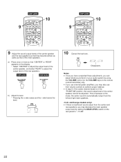
DSP-A592 DSP-A492 DELAY/CENTER /REAR/SWFR DELAY/CENTER /REAR b) Adjust its level. * Pressing the + side raises and the - TIME/ LEVEL + 10 Cancel the test tone. a) Press once or more so that of the rear speakers. TEST Disappears. q If you use their volume controls... the output level of the main speakers. PRESET + A/B/C/D/E TUNER DISC PLAY CD PHONO POWER SLEEP VOLUME 10 9 DSP-A492 - + TIME/ LEVEL DELAY/CENTER /REAR TEST EFFECT PROGRAM PROLOGIC ENHANCED ON/OFF VCR TV/DBS DVD/LD DIR... "CENTER" or "REAR" appears on the remote control transmitter) only.
DSP-A592 DSP-A492 DELAY/CENTER /REAR/SWFR DELAY/CENTER /REAR b) Adjust its level. * Pressing the + side raises and the - TIME/ LEVEL + 10 Cancel the test tone. a) Press once or more so that of the rear speakers. TEST Disappears. q If you use their volume controls... the output level of the main speakers. PRESET + A/B/C/D/E TUNER DISC PLAY CD PHONO POWER SLEEP VOLUME 10 9 DSP-A492 - + TIME/ LEVEL DELAY/CENTER /REAR TEST EFFECT PROGRAM PROLOGIC ENHANCED ON/OFF VCR TV/DBS DVD/LD DIR... "CENTER" or "REAR" appears on the remote control transmitter) only.
Owner's Manual
Page 28
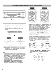
...- However, if the center channel mode is heard from the main speakers and the rear speakers. q To select a DSP program on the remote control transmitter, first turn the DSP on the display by pressing the EFFECT key. PROLOGIC ENHANCED 28 q When a monaural sound source is played with DOLBY ...a program, it is automatically called. q If you select the input source next time, the same program is linked with the digital sound field processor DSP-A592 DSP-A492 2 l6 20 28 l2 8 40 4 60 2 0 -dB - + TIME/ LEVEL DELAY/CENTER /REAR/SWFR TEST EFFECT PROGRAM PROLOGIC ENHANCED ON...
...- However, if the center channel mode is heard from the main speakers and the rear speakers. q To select a DSP program on the remote control transmitter, first turn the DSP on the display by pressing the EFFECT key. PROLOGIC ENHANCED 28 q When a monaural sound source is played with DOLBY ...a program, it is automatically called. q If you select the input source next time, the same program is linked with the digital sound field processor DSP-A592 DSP-A492 2 l6 20 28 l2 8 40 4 60 2 0 -dB - + TIME/ LEVEL DELAY/CENTER /REAR/SWFR TEST EFFECT PROGRAM PROLOGIC ENHANCED ON...

Owner's Manual
Page 31
... SLEEP timer setting can also be canceled by turning off automatically. Notes q The SLEEP timer can make this unit turn off the power with the remote control transmitter. Whenever the SLEEP key is set the SLEEP time 1 SLEEP To cancel the selected SLEEP time SLEEP Press once or more so that "SLEEP...
... SLEEP timer setting can also be canceled by turning off automatically. Notes q The SLEEP timer can make this unit turn off the power with the remote control transmitter. Whenever the SLEEP key is set the SLEEP time 1 SLEEP To cancel the selected SLEEP time SLEEP Press once or more so that "SLEEP...

Owner's Manual
Page 32
...Connect the cords properly. Connect the cords properly. Raise the sound output level to the rear speakers. Select the appropriate program. Remote control transmitter Others 32 Incorrect setting of the main unit. The power to the component connected to this unit is not listed in ...persists, the cords may be increased, or sound is played in the SYMPTOM column, disconnect the power cord and contact your authorized YAMAHA dealer or service center for the monaural sound source. The protection circuit has been activated because of flourescent lamp etc.) is not ...
...Connect the cords properly. Connect the cords properly. Raise the sound output level to the rear speakers. Select the appropriate program. Remote control transmitter Others 32 Incorrect setting of the main unit. The power to the component connected to this unit is not listed in ...persists, the cords may be increased, or sound is played in the SYMPTOM column, disconnect the power cord and contact your authorized YAMAHA dealer or service center for the monaural sound source. The protection circuit has been activated because of flourescent lamp etc.) is not ...

Owner's Manual
Page 33
English SPECIFICATIONS AUDIO SECTION Minimum RMS Output Power per Channel Main L, R 8 ohms, 20 Hz to 20 kHz, 0.04% THD
English SPECIFICATIONS AUDIO SECTION Minimum RMS Output Power per Channel Main L, R 8 ohms, 20 Hz to 20 kHz, 0.04% THD


