
Owners Manual
Page 3
... or Yamaha representative of assurance that your use only high quality shielded cables. This product, when installed as indicated in the instructions contained in as follows: The wire which is 300 ohm ribbon lead, change the lead-in to distribute this type of this manual, meets FCC requirements. IMPORTANT: When connecting this mains lead are on virheellisesti asennettu. Utilize power outlets...
... or Yamaha representative of assurance that your use only high quality shielded cables. This product, when installed as indicated in the instructions contained in as follows: The wire which is 300 ohm ribbon lead, change the lead-in to distribute this type of this manual, meets FCC requirements. IMPORTANT: When connecting this mains lead are on virheellisesti asennettu. Utilize power outlets...

Owners Manual
Page 4
... device contains no user-serviceable parts. Pulling by the cord can result in a safe place for the device. Location • Before moving the device, remove all equalizer controls and faders to their maximum. If some trouble or malfunction occurs, immediately turn off the power switch, disconnect the electric plug from the outlet, and have the device inspected by qualified Yamaha service personnel. • If this manual...
... device contains no user-serviceable parts. Pulling by the cord can result in a safe place for the device. Location • Before moving the device, remove all equalizer controls and faders to their maximum. If some trouble or malfunction occurs, immediately turn off the power switch, disconnect the electric plug from the outlet, and have the device inspected by qualified Yamaha service personnel. • If this manual...

Owners Manual
Page 5
... Audio are trademarks of time at the front and rear to an external devices such as switches, volume controls, and connectors, deteriorates over time. If you unplug the power cord from the AC outlet, the internal SRAM data is provided on or off the power immediately and unplug the power cord from the actual equipment. • The bitmap fonts used in the vicinity of a TV, radio, stereo...
... Audio are trademarks of time at the front and rear to an external devices such as switches, volume controls, and connectors, deteriorates over time. If you unplug the power cord from the AC outlet, the internal SRAM data is provided on or off the power immediately and unplug the power cord from the actual equipment. • The bitmap fonts used in the vicinity of a TV, radio, stereo...

Owners Manual
Page 7
... External Device 28 Remote Connection ([REMOTE] Connector). 28 Controlling external head amplifiers from the DME64N/24N .28 Controlling a DME24N's internal head amps from a digital mixer . 29 Controlling the DME64N/24N from an external device 29 MIDI Connection ([MIDI] Connectors) . . . . . 30 Cascade Connection ([Cascade] Connectors) (DME64N only 31 WORD CLOCK Connection ([WORD CLOCK] Connectors 32 GPI Connection ([GPI] Connectors 33 Panel Operation and Displays 34 Basic Operation 34 Main Display 35 Parameter Edit Displays 36 Editing User Defined Button 38 Mute Switching 39 Output...
... External Device 28 Remote Connection ([REMOTE] Connector). 28 Controlling external head amplifiers from the DME64N/24N .28 Controlling a DME24N's internal head amps from a digital mixer . 29 Controlling the DME64N/24N from an external device 29 MIDI Connection ([MIDI] Connectors) . . . . . 30 Cascade Connection ([Cascade] Connectors) (DME64N only 31 WORD CLOCK Connection ([WORD CLOCK] Connectors 32 GPI Connection ([GPI] Connectors 33 Panel Operation and Displays 34 Basic Operation 34 Main Display 35 Parameter Edit Displays 36 Editing User Defined Button 38 Mute Switching 39 Output...
Owners Manual
Page 8
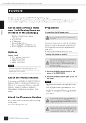
... Control Panel NOTE For more information on your speaker system, turn the devices on the power to turn off the power to read this manual, models DME64N, DME24N, DME8i-C, DME8o-C, DME4io-C, DME8i-ES, DME8o-ES and DME4io-ES are categorized as the DME Designer Owner's Manual. Press the [POWER] switch to turn on in the following Yamaha website. Otherwise, a malfunction may occur. http://www.yamahaproaudio.com/ Preparation Connecting the...
... Control Panel NOTE For more information on your speaker system, turn the devices on the power to turn off the power to read this manual, models DME64N, DME24N, DME8i-C, DME8o-C, DME4io-C, DME8i-ES, DME8o-ES and DME4io-ES are categorized as the DME Designer Owner's Manual. Press the [POWER] switch to turn on in the following Yamaha website. Otherwise, a malfunction may occur. http://www.yamahaproaudio.com/ Preparation Connecting the...

Owners Manual
Page 9
... Owner's Manual for details. If a computer is connected to the network, you to control the device from the ICP1 and the DME64N/DME24N. Components and parameters The individual audio processing modules (equalizers, compressors, etc.) are also available as a single audio system. External head amplifier control modules are called an "area." Changing the parameters of components enables control over the operation of preset parameters. Refer to basic mixing and matrix output...
... Owner's Manual for details. If a computer is connected to the network, you to control the device from the ICP1 and the DME64N/DME24N. Components and parameters The individual audio processing modules (equalizers, compressors, etc.) are also available as a single audio system. External head amplifier control modules are called an "area." Changing the parameters of components enables control over the operation of preset parameters. Refer to basic mixing and matrix output...
Owners Manual
Page 13
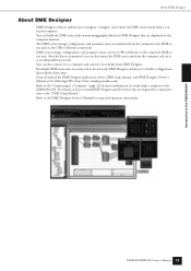
... setup manual, and DME Designer Owner's Manual at the following URL: http://www.yamahaproaudio.com/ Refer to the "Connecting to a Computer" (page 22) for setup and operation instructions. Refer to the DME Designer Owner's Manual for more information on connecting a computer to the DME64N/24N. DME series settings, configuration, and parameter data is transmitted, you to integrate, configure, and control the DME series system from a connected computer. DME64N/DME24N Owner's Manual...
... setup manual, and DME Designer Owner's Manual at the following URL: http://www.yamahaproaudio.com/ Refer to the "Connecting to a Computer" (page 22) for setup and operation instructions. Refer to the DME Designer Owner's Manual for more information on connecting a computer to the DME64N/24N. DME series settings, configuration, and parameter data is transmitted, you to integrate, configure, and control the DME series system from a connected computer. DME64N/DME24N Owner's Manual...

Owners Manual
Page 15
... in analog audio inputs or outputs ([IN] and [OUT] connectors). 9 [SCENE NUMBER] Indicator Shows the current scene number. ) Display Displays scene information and device parameters. ! [SCENE] Button Calls the scene recall/store display (page 39). CAUTION When you are not using the product for device group master setup instructions. 7 [PEAK] Indicator (DME24N only) Light red when a signal on and off , electricity is showing the [HOME] button steps through the user-de...
... in analog audio inputs or outputs ([IN] and [OUT] connectors). 9 [SCENE NUMBER] Indicator Shows the current scene number. ) Display Displays scene information and device parameters. ! [SCENE] Button Calls the scene recall/store display (page 39). CAUTION When you are not using the product for device group master setup instructions. 7 [PEAK] Indicator (DME24N only) Light red when a signal on and off , electricity is showing the [HOME] button steps through the user-de...

Owners Manual
Page 17
...] connector. DME64N/DME24N Owner's Manual 17 Each of other DME series units. Refer to "I/O Card Installation" on page 23 for connection details. 5 [WORD CLOCK IN] [WORD CLOCK OUT] Connectors These BNC connector receive and transmit word clock from AMX or Crestron. Word clock settings are balanced Euroblock connectors for connection details. The Controls and Connectors Rear Panel 4 [MIDI IN] [MIDI OUT] [MIDI THRU] Connectors These are to be directly connected a "cross" cable should be supplied to...
...] connector. DME64N/DME24N Owner's Manual 17 Each of other DME series units. Refer to "I/O Card Installation" on page 23 for connection details. 5 [WORD CLOCK IN] [WORD CLOCK OUT] Connectors These BNC connector receive and transmit word clock from AMX or Crestron. Word clock settings are balanced Euroblock connectors for connection details. The Controls and Connectors Rear Panel 4 [MIDI IN] [MIDI OUT] [MIDI THRU] Connectors These are to be directly connected a "cross" cable should be supplied to...

Owners Manual
Page 18
... front panel. Install any required I /O Card Installation" on page 67 for operation. 1. Be sure to properly ground the device to turn all devices OFF before connecting AC mains power. Do not use of electrical shock. WARNING The type of about 20 millimeters between the front panel and the cover. 18 DME64N/DME24N Owner's Manual Preparation Connect the AC power cord. Use only the AC power cord supplied with the DME64N/24N. The use a plug adapter...
... front panel. Install any required I /O Card Installation" on page 67 for operation. 1. Be sure to properly ground the device to turn all devices OFF before connecting AC mains power. Do not use of electrical shock. WARNING The type of about 20 millimeters between the front panel and the cover. 18 DME64N/DME24N Owner's Manual Preparation Connect the AC power cord. Use only the AC power cord supplied with the DME64N/24N. The use a plug adapter...
Owners Manual
Page 22
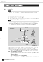
... two ways: (1) Control the DME64N/24N from a MIDI sequencer or similar software. USB Connection Connecting to a Computer USB Connection NOTE • Refer to the "DME Setup Manual" (PDF file) for use by a MIDI sequencer or other application. Connecting to a Computer Device Group USB Cable USB DME Satellite PEA K SIGNAL PEA K SIGNAL INPUT PEA K SIGNAL PEA K SIGNAL INPUT PEA K SIGNAL PEA K SIGNAL DIGITAL MIXING ENGINE SATELLITE Ethernet Cable Switching Hub Computer...
... two ways: (1) Control the DME64N/24N from a MIDI sequencer or similar software. USB Connection Connecting to a Computer USB Connection NOTE • Refer to the "DME Setup Manual" (PDF file) for use by a MIDI sequencer or other application. Connecting to a Computer Device Group USB Cable USB DME Satellite PEA K SIGNAL PEA K SIGNAL INPUT PEA K SIGNAL PEA K SIGNAL INPUT PEA K SIGNAL PEA K SIGNAL DIGITAL MIXING ENGINE SATELLITE Ethernet Cable Switching Hub Computer...
Owners Manual
Page 33
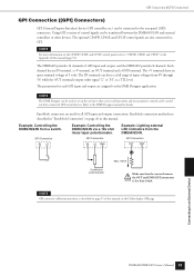
... Example: Lighting external LED indicators from a switch. NOTE GPI connector calibration procedure is less than 16mA. The optional CP4SW, CP4SF, and CP1SF control panels are used to an External Device DME64N/DME24N Owner's Manual 33 NOTE For more information on page 26 in the Utility display GPI page. NOTE The DME Designer can be connected to the rear-panel [GPI] connectors. Connecting to set up the system so...
... Example: Lighting external LED indicators from a switch. NOTE GPI connector calibration procedure is less than 16mA. The optional CP4SW, CP4SF, and CP1SF control panels are used to an External Device DME64N/DME24N Owner's Manual 33 NOTE For more information on page 26 in the Utility display GPI page. NOTE The DME Designer can be connected to the rear-panel [GPI] connectors. Connecting to set up the system so...

Owners Manual
Page 35
... is not linked within a device group. 5 Mute Indicator Shows the current mute ON/OFF status. : Mute ON : Mute OFF 6 Output Level Indicator Displays the current output level in 10 increments. Up to the leftmost position after the power is turned ON. : Panel Lock ON (Panel controls locked) Panel Operation and Displays DME64N/DME24N Owner's Manual 35 When "two-byte" characters are specified by using the...
... is not linked within a device group. 5 Mute Indicator Shows the current mute ON/OFF status. : Mute ON : Mute OFF 6 Output Level Indicator Displays the current output level in 10 increments. Up to the leftmost position after the power is turned ON. : Panel Lock ON (Panel controls locked) Panel Operation and Displays DME64N/DME24N Owner's Manual 35 When "two-byte" characters are specified by using the...

Owners Manual
Page 44
... 54 Panel Operation and Displays 44 DME64N/DME24N Owner's Manual Resets the GPI calibration. Current status and setup for individual head amplifier channel high-pass filter frequency. Current status and setup for the internal and connected external head amplifiers. Current status and setup for the device's IP address. Determines the connector that will be accessed via cards plugged in a DME64N/24N...
... 54 Panel Operation and Displays 44 DME64N/DME24N Owner's Manual Resets the GPI calibration. Current status and setup for individual head amplifier channel high-pass filter frequency. Current status and setup for the internal and connected external head amplifiers. Current status and setup for the device's IP address. Determines the connector that will be accessed via cards plugged in a DME64N/24N...

Owners Manual
Page 48
... GPI control input. ON: The display is very important! Slow: The meters fall time of the four User Defined Button pages. OFF: The display lights when a control is operated, and will appear when the [UTILITY] key is pressed to the device is displayed, but cannot be set to alternately turn the setting "ON" and "OFF." To change the settings use the Panel lock feature. Lock: A password must be operated...
... GPI control input. ON: The display is very important! Slow: The meters fall time of the four User Defined Button pages. OFF: The display lights when a control is operated, and will appear when the [UTILITY] key is pressed to the device is displayed, but cannot be set to alternately turn the setting "ON" and "OFF." To change the settings use the Panel lock feature. Lock: A password must be operated...
Owners Manual
Page 58
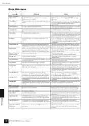
... operating the unit, and contact a Yamaha dealer for battery replacement. If the problem persists, contact a Yamaha dealer. Communication with the clock signal being received at the [CASCADE OUT] connector. Recall a Scene! The backup battery voltage is completely discharged or not installed. Make sure that the DME64N/24N and the card or signal being received at your password, contact a Yamaha dealer. If you have lost and reset to use...
... operating the unit, and contact a Yamaha dealer for battery replacement. If the problem persists, contact a Yamaha dealer. Communication with the clock signal being received at the [CASCADE OUT] connector. Recall a Scene! The backup battery voltage is completely discharged or not installed. Make sure that the DME64N/24N and the card or signal being received at your password, contact a Yamaha dealer. If you have lost and reset to use...

Owners Manual
Page 59
... scene. Do NOT turn power off while the unit displays this problem to a Yamaha dealer. Refer this problem to a Yamaha dealer. - - - - - Set an appropriate network IP address. Refer this problem to a contact a Yamaha dealer. A file operation is not possible. Preparing network connection. Panel operation not allowed. Change the IP addresses so that the DME64N and the card or external source supplying the word clock are set up via DME...
... scene. Do NOT turn power off while the unit displays this problem to a Yamaha dealer. Refer this problem to a Yamaha dealer. - - - - - Set an appropriate network IP address. Refer this problem to a contact a Yamaha dealer. A file operation is not possible. Preparing network connection. Panel operation not allowed. Change the IP addresses so that the DME64N and the card or external source supplying the word clock are set up via DME...
Owners Manual
Page 61
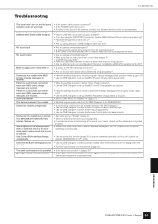
... before switching clock sources. • Use the panel lock function (page 38) to prevent unwanted operation of the panel controls on (page 48)? Scenes can 't be operated. The Utility screen cannot be opened. • Is the power cable properly connected? • Is the POWER switch turned on ? • Are the MIDI ports properly set up (page 51)? • Are the receive and transmit device channels set appropriately? • Have the settings required to receive program change messages...
... before switching clock sources. • Use the panel lock function (page 38) to prevent unwanted operation of the panel controls on (page 48)? Scenes can 't be operated. The Utility screen cannot be opened. • Is the power cable properly connected? • Is the POWER switch turned on ? • Are the MIDI ports properly set up (page 51)? • Are the receive and transmit device channels set appropriately? • Have the settings required to receive program change messages...

Owners Manual
Page 73
A digital audio connection format used for high-frequency connections using screws. Eight channels of connector used by a single optical "Tos-Link" cable. A type of digital audio can be in effect when a device is powered on for the first time after it is an independent address assigned to 10 MHz. Yamaha cascade connections employ half-pitch 68-pin D-Sub connectors. The basic modules that are combined to create DME64N/24N audio systems. In addition to 100...
A digital audio connection format used for high-frequency connections using screws. Eight channels of connector used by a single optical "Tos-Link" cable. A type of digital audio can be in effect when a device is powered on for the first time after it is an independent address assigned to 10 MHz. Yamaha cascade connections employ half-pitch 68-pin D-Sub connectors. The basic modules that are combined to create DME64N/24N audio systems. In addition to 100...

Owners Manual
Page 76
... Target 47 Parameter Change 50 Parameter Edit display 35 Peak Hold (Level Meter display 41 Peak Hold (Spectrum display 40 [PEAK] Indicator 15 Phantom Master Switch 53 Phantom Power (Glossary 70 [PHONES] Jack 15 [PHONES LEVEL] Control 15 [POWER] Switch 15 preparation 18, 26 preset parameter (Glossary 70 Probe Monitor Function 40 Program Change 50 R rear panel 16 Remote (Misc Page 48 Remote Connection 28 [REMOTE] Connector 17, 28 Reset (GPI Page 52...
... Target 47 Parameter Change 50 Parameter Edit display 35 Peak Hold (Level Meter display 41 Peak Hold (Spectrum display 40 [PEAK] Indicator 15 Phantom Master Switch 53 Phantom Power (Glossary 70 [PHONES] Jack 15 [PHONES LEVEL] Control 15 [POWER] Switch 15 preparation 18, 26 preset parameter (Glossary 70 Probe Monitor Function 40 Program Change 50 R rear panel 16 Remote (Misc Page 48 Remote Connection 28 [REMOTE] Connector 17, 28 Reset (GPI Page 52...

