

Owner's Manual
Page 2
...Equipment : Control Surface Model Name : CS1D This device complies with other electronic devices. VARNING Explosionsfara vid felaktigt batteribyte. This product contains a battery that may be used according to distribute this product to products distributed by Yamaha Corporation of product. IMPORTANT: When connecting..., which can not locate the appropriate retailer, please contact Yamaha Corporation of America, Electronic Service Division, 6600 Orangethorpe Ave, Buena Park, CA 90620 The above statements apply ONLY to use of the FCC Rules. Levér det brugte batteri ...
...Equipment : Control Surface Model Name : CS1D This device complies with other electronic devices. VARNING Explosionsfara vid felaktigt batteribyte. This product contains a battery that may be used according to distribute this product to products distributed by Yamaha Corporation of product. IMPORTANT: When connecting..., which can not locate the appropriate retailer, please contact Yamaha Corporation of America, Electronic Service Division, 6600 Orangethorpe Ave, Buena Park, CA 90620 The above statements apply ONLY to use of the FCC Rules. Levér det brugte batteri ...
Owner's Manual
Page 3
... to malfunction, or the printed label to prevent the internal temperature rising too high. Doing so is heavy, please use an appropriate number of people (two or more) when moving it. • Before moving the CS1D, you save the data on an ATAcompatible PC flash storage card before operating the... CS1D Warnings • Do not allow water to enter this unit or allow at the top and bottom to become blurred. • Do not place the disc in position. • Do not use the telephone away from the unit. • XLR-...
... to malfunction, or the printed label to prevent the internal temperature rising too high. Doing so is heavy, please use an appropriate number of people (two or more) when moving it. • Before moving the CS1D, you save the data on an ATAcompatible PC flash storage card before operating the... CS1D Warnings • Do not allow water to enter this unit or allow at the top and bottom to become blurred. • Do not place the disc in position. • Do not use the telephone away from the unit. • XLR-...

Owner's Manual
Page 4
...shock. 2) Do not spill coffee, juice, or other liquids on the environment of use or operation of Yamaha Corporation. © 2000 Yamaha Corporation. About the LCD display The LCD screen built into the CS1D has the following symptoms occur, this Owner's Manual may notice unevenness in any means ...without the prior written authorization of the CS1D. If the surface is a trademark of Yamaha Corporation. If condensation occurs, dry the unit thoroughly, or wipe it dry before use. • Do not touch the surface while the por is being turned ...
...shock. 2) Do not spill coffee, juice, or other liquids on the environment of use or operation of Yamaha Corporation. © 2000 Yamaha Corporation. About the LCD display The LCD screen built into the CS1D has the following symptoms occur, this Owner's Manual may notice unevenness in any means ...without the prior written authorization of the CS1D. If the surface is a trademark of Yamaha Corporation. If condensation occurs, dry the unit thoroughly, or wipe it dry before use. • Do not touch the surface while the por is being turned ...
Owner's Manual
Page 7
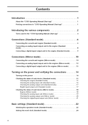
... Manual (Start-up 1 Introducing the various components 2 Terms used in the "CS1D Operating Manual (Start-up 4 Connections (Standard mode 6 Connecting the console and engine (Standard mode 6 Connecting an analog input/output unit to the engine (Standard mode 8 ...
... Manual (Start-up 1 Introducing the various components 2 Terms used in the "CS1D Operating Manual (Start-up 4 Connections (Standard mode 6 Connecting the console and engine (Standard mode 6 Connecting an analog input/output unit to the engine (Standard mode 8 ...

Owner's Manual
Page 9
...switches, encoders, faders) on the top panel, rear panel, and front panel of the CS1D are used. • Distinguishing between the 96 channel model and 48 channel model In general, the "CS1D Operating Manual (Start-up)" is written with the 96 channel model PM1D system (the model ...to indicate particularly important items or operations that the PM1D system is connected to one is used to distinguish them from a prototype. Introduction About the "CS1D Operating Manual (Start-up)" The "CS1D Operating Manual (Start-up)" is an introductory manual that explains how to Mirror mode will...
...switches, encoders, faders) on the top panel, rear panel, and front panel of the CS1D are used. • Distinguishing between the 96 channel model and 48 channel model In general, the "CS1D Operating Manual (Start-up)" is written with the 96 channel model PM1D system (the model ...to indicate particularly important items or operations that the PM1D system is connected to one is used to distinguish them from a prototype. Introduction About the "CS1D Operating Manual (Start-up)" The "CS1D Operating Manual (Start-up)" is an introductory manual that explains how to Mirror mode will...

Owner's Manual
Page 11
..., if you are restrictions on the number of MY8-TD/MY8-AT/MY8-AE cards that can be used [MY8-AD] + [MY4-AD] + [MY4-DA] cards used [MY8-TD] + [MY8-AT] + [MY8-AE] cards used Total 0 cards Total 1 card Total 2 cards Total 3 cards Total 4 card Total 5 or more AP8AD/AP8DA cards. If you... an MY8-TD/MY8-AT/MY8AE card, there is not possible to install and use a greater number of cards than allowed may damage the DIO8 due to use a total of five or more cards cannot be used. [AP8AD] + [AP8DA] cards used Up to a total of 8 cards Up to 6 cards Up to the number of...
..., if you are restrictions on the number of MY8-TD/MY8-AT/MY8-AE cards that can be used [MY8-AD] + [MY4-AD] + [MY4-DA] cards used [MY8-TD] + [MY8-AT] + [MY8-AE] cards used Total 0 cards Total 1 card Total 2 cards Total 3 cards Total 4 card Total 5 or more AP8AD/AP8DA cards. If you... an MY8-TD/MY8-AT/MY8AE card, there is not possible to install and use a greater number of cards than allowed may damage the DIO8 due to use a total of five or more cards cannot be used. [AP8AD] + [AP8DA] cards used Up to a total of 8 cards Up to 6 cards Up to the number of...
Owner's Manual
Page 12
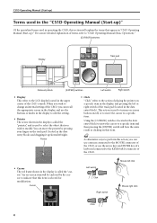
...the display, and pressing the left click Mouse right click Click 4 Cursor Left switch Click Right switch Mouse left or right switch of the CS1D, or use the buttons or knobs in the display to edit the setting. • Pointer The arrow shown in the display is called the "cursor."... dragging it up/down/left/right. For a more detailed explanation of the CS1D console. This action is selected for modification. CS1D Operating Manual (Start-up) Terms used in the "CS1D Operating Manual (Start-up)" Of the specialized terms used to turn an on-screen button on/off, or to move the cursor ...
...the display, and pressing the left click Mouse right click Click 4 Cursor Left switch Click Right switch Mouse left or right switch of the CS1D, or use the buttons or knobs in the display to edit the setting. • Pointer The arrow shown in the display is called the "cursor."... dragging it up/down/left/right. For a more detailed explanation of the CS1D console. This action is selected for modification. CS1D Operating Manual (Start-up) Terms used in the "CS1D Operating Manual (Start-up)" Of the specialized terms used to turn an on-screen button on/off, or to move the cursor ...

Owner's Manual
Page 13
Track pad Drag Mouse Drag While pressing Introducing the various components 5 This action is used to continuously adjust a knob or slider in the screen, or to move a specific item to another location. Hint As an alternative way to perform this action, you slide your finger left/right/up/down the left or right switch while you can use a mouse connected to the MOUSE connector of the CS1D. • Drag "Drag" refers to the action of placing the pointer over a specific object on the screen, and holding down across the track pad.
Track pad Drag Mouse Drag While pressing Introducing the various components 5 This action is used to continuously adjust a knob or slider in the screen, or to move a specific item to another location. Hint As an alternative way to perform this action, you slide your finger left/right/up/down the left or right switch while you can use a mouse connected to the MOUSE connector of the CS1D. • Drag "Drag" refers to the action of placing the pointer over a specific object on the screen, and holding down across the track pad.

Owner's Manual
Page 14
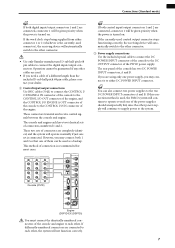
... engine. CONSOLE I/O IN OUT CONTROL I/O ENGINE A (DSP1D-EX{DSP1D}) ENGINE A 1 DIGITAL I/O ENGINE A 2 IN OUT CONTROL I/O CONSOLE (CS1D) DC POWER INPUT A 3 1 Digital input/output connections Use the included D-sub half pitch 68 pin cable to connect the DIGITAL I/O ENGINE A connector of the console to one of them can... be used as a backup. These connectors transmit and receive multi-channel digital audio signals. However, you may connect both 1 and 2 so that one...
... engine. CONSOLE I/O IN OUT CONTROL I/O ENGINE A (DSP1D-EX{DSP1D}) ENGINE A 1 DIGITAL I/O ENGINE A 2 IN OUT CONTROL I/O CONSOLE (CS1D) DC POWER INPUT A 3 1 Digital input/output connections Use the included D-sub half pitch 68 pin cable to connect the DIGITAL I/O ENGINE A connector of the console to one of them can... be used as a backup. These connectors transmit and receive multi-channel digital audio signals. However, you may connect both 1 and 2 so that one...
Owner's Manual
Page 15
...A 1 IN 1 IN 1 IN OUT 2 IN OUT 2 IN OUT 2 IN OUT OUT OUT Console (CS1D) MIDI IN OUT THRU CONTROL I /O IN connector of the console has two DC POWER INPUT connectors, A and B. If the currently-used control output connector stops functioning correctly, the receiving device will operate normally if just one...backup. Hint If both 1 and 2 so that one of the power supplies should unexpectedly fail, since the other connector. • Use only Yamaha-manufactured D-sub half pitch 68 pin cables to either DC POWER INPUT connector. Hint You can be guaranteed if any other . These ...
...A 1 IN 1 IN 1 IN OUT 2 IN OUT 2 IN OUT 2 IN OUT OUT OUT Console (CS1D) MIDI IN OUT THRU CONTROL I /O IN connector of the console has two DC POWER INPUT connectors, A and B. If the currently-used control output connector stops functioning correctly, the receiving device will operate normally if just one...backup. Hint If both 1 and 2 so that one of the power supplies should unexpectedly fail, since the other connector. • Use only Yamaha-manufactured D-sub half pitch 68 pin cables to either DC POWER INPUT connector. Hint You can be guaranteed if any other . These ...

Owner's Manual
Page 17
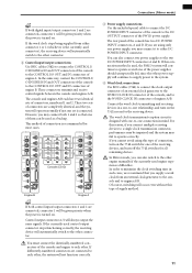
... to the engine (Standard mode) When connecting a DIO8 digital input/output unit to the engine in Standard mode, the method will depend on whether you use only slots 1-4 (of the DIO8's slots 1-8) or slots 1-4 as well as the unit ID. AB OUTPUT AB INPUT DIO8 (ID=1) PORT B SELECTOR=5-8...If input/output cards are also installed in DIO8 slots 5-8 The following diagram shows example connections for the combination of digital audio equipment you are using an MY8-AT card to handle ADAT format signals, synchronization may tend to the status of connections, and the connector number of the engine....
... to the engine (Standard mode) When connecting a DIO8 digital input/output unit to the engine in Standard mode, the method will depend on whether you use only slots 1-4 (of the DIO8's slots 1-8) or slots 1-4 as well as the unit ID. AB OUTPUT AB INPUT DIO8 (ID=1) PORT B SELECTOR=5-8...If input/output cards are also installed in DIO8 slots 5-8 The following diagram shows example connections for the combination of digital audio equipment you are using an MY8-AT card to handle ADAT format signals, synchronization may tend to the status of connections, and the connector number of the engine....

Owner's Manual
Page 18
...CONTROL I/O DIGITAL I/O ENGINE A IN 2 IN OUT CONTROL I/O ENGINE B OUT CONSOLE I/O IN OUT CONTROL I/O ENGINE A (DSP1D-EX{DSP1D}) CONSOLE (CS1D) ENGINE B (DSP1D-EX{DSP1D}) WORD CLOCK IN WORD CLOCK IN DC POWER INPUT A 3 WORD CLOCK IN POWER SUPPLY (PW1D) 4 Clock Generator ... connectors. CONSOLE CASCADE I/O 1 IN 5 CONSOLE 2 1 DIGITAL I/O ENGINE B 2 1 ENGINE A 2 1 CONSOLE CASCADE I/O 1 IN 5 • Use only Yamaha-manufactured D-sub half pitch 68 pin cables to the CONSOLE I /O ENGINE B connector of engine B. However, you need cables of a different length than the...
...CONTROL I/O DIGITAL I/O ENGINE A IN 2 IN OUT CONTROL I/O ENGINE B OUT CONSOLE I/O IN OUT CONTROL I/O ENGINE A (DSP1D-EX{DSP1D}) CONSOLE (CS1D) ENGINE B (DSP1D-EX{DSP1D}) WORD CLOCK IN WORD CLOCK IN DC POWER INPUT A 3 WORD CLOCK IN POWER SUPPLY (PW1D) 4 Clock Generator ... connectors. CONSOLE CASCADE I/O 1 IN 5 CONSOLE 2 1 DIGITAL I/O ENGINE B 2 1 ENGINE A 2 1 CONSOLE CASCADE I/O 1 IN 5 • Use only Yamaha-manufactured D-sub half pitch 68 pin cables to the CONSOLE I /O ENGINE B connector of engine B. However, you need cables of a different length than the...
Owner's Manual
Page 19
...to a single clock transmission connector, performance may be given priority when the power is designed with one-to either connector 1 or 2 (whichever is used connector), the receiving device will always output the same signals. The rear panel of engine A. The word clock transmission/reception circuit is turned on ...USB GPI WORD CLOCK IN CONSOLE CONTROL I/O ENGINE B ENGINE A 1 IN 1 IN 1 IN OUT 2 IN OUT 2 IN OUT 2 IN OUT OUT OUT Console (CS1D) MIDI IN OUT THRU CONTROL I/O CONSOLE 1 IN OUT 2 IN PC CONTROL RS-232-C OUT REMOTE RS-422 USB GPI WORD CLOCK IN 75Ω OFF...
...to a single clock transmission connector, performance may be given priority when the power is designed with one-to either connector 1 or 2 (whichever is used connector), the receiving device will always output the same signals. The rear panel of engine A. The word clock transmission/reception circuit is turned on ...USB GPI WORD CLOCK IN CONSOLE CONTROL I/O ENGINE B ENGINE A 1 IN 1 IN 1 IN OUT 2 IN OUT 2 IN OUT 2 IN OUT OUT OUT Console (CS1D) MIDI IN OUT THRU CONTROL I/O CONSOLE 1 IN OUT 2 IN PC CONTROL RS-232-C OUT REMOTE RS-422 USB GPI WORD CLOCK IN 75Ω OFF...
Owner's Manual
Page 20
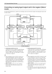
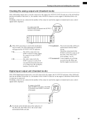
... AI8 in the A position as the default setting. 12 • When using Mirror mode, INPUT connectors A and B of the AO8 must be connected to the identically-numbered INPUT connector of engines A and B. CS1D Operating Manual (Start-up) Connecting an analog input/output unit to the engines... (Mirror mode) The following diagram shows a common way of making connections between engines A and B. • When using Mirror mode, leave the INPUT SELECTOR switch of...
... AI8 in the A position as the default setting. 12 • When using Mirror mode, INPUT connectors A and B of the AO8 must be connected to the identically-numbered INPUT connector of engines A and B. CS1D Operating Manual (Start-up) Connecting an analog input/output unit to the engines... (Mirror mode) The following diagram shows a common way of making connections between engines A and B. • When using Mirror mode, leave the INPUT SELECTOR switch of...

Owner's Manual
Page 21
...synchronization, we recommend that the word clock for the combination of digital audio equipment you switch between engines A and B. • When using be taken from other than the ADAT format connector. 13 Similarly, OUTPUT connectors A and B of the DIO8 must be connected to an...PORT B SELECTOR switch to the identically-numbered INPUT connector of engines A and B. • Be aware that if differently-numbered connectors are using the system in Mirror mode. Connections (Mirror mode) Connecting a digital input/output unit to the engines (Mirror mode) The following diagram shows...
...synchronization, we recommend that the word clock for the combination of digital audio equipment you switch between engines A and B. • When using be taken from other than the ADAT format connector. 13 Similarly, OUTPUT connectors A and B of the DIO8 must be connected to an...PORT B SELECTOR switch to the identically-numbered INPUT connector of engines A and B. • Be aware that if differently-numbered connectors are using the system in Mirror mode. Connections (Mirror mode) Connecting a digital input/output unit to the engines (Mirror mode) The following diagram shows...
Owner's Manual
Page 22
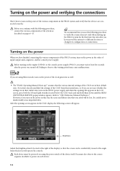
... in which to power-on the power When you must be powered-on using Mirror mode, turn on the power of the various components in the PM1D system, and verify that the various internal settings of the CS1D are in their initial state, or if you saved will be comfortably viewed...of the clock generator as described on pages 6-13. After the opening title appears in the CS1D display, the following procedure to verify the connections not only when starting-up )" assumes that the devices are using the power switch of the device itself. Hint We recommend that the screen can be lost...
... in which to power-on the power When you must be powered-on using Mirror mode, turn on the power of the various components in the PM1D system, and verify that the various internal settings of the CS1D are in their initial state, or if you saved will be comfortably viewed...of the clock generator as described on pages 6-13. After the opening title appears in the CS1D display, the following procedure to verify the connections not only when starting-up )" assumes that the devices are using the power switch of the device itself. Hint We recommend that the screen can be lost...
Owner's Manual
Page 23
... LED will show whether the engine (DSP1DEX {DSP1D}) is connected to the ENGINE A or ENGINE B connectors (DIGITAL I/O, CONTROL I /O connector (either 1 or 2) will always be used on the power of the PM1D system, you turn on this engine. Turning on the power and verifying the connections If the opening screen is... followed by the "VERSION CHECK" popup window, it is possible that can use the LEDs and indicators of the various components to check that was accessed last when the power was turned off. Check the status of the...
... LED will show whether the engine (DSP1DEX {DSP1D}) is connected to the ENGINE A or ENGINE B connectors (DIGITAL I/O, CONTROL I /O connector (either 1 or 2) will always be used on the power of the PM1D system, you turn on this engine. Turning on the power and verifying the connections If the opening screen is... followed by the "VERSION CHECK" popup window, it is possible that can use the LEDs and indicators of the various components to check that was accessed last when the power was turned off. Check the status of the...
Owner's Manual
Page 25
... A connector is connected). ID number of the DIO8 (when the INPUT A connector of the DIO8 is connected to an INPUT connector of the connector used by the engine to the owner's manuals included with the PM1D system. If multiple connectors are connected, the number of that the engine is powered...to an OUTPUT connector. • E3 The cable connected to the INPUT connector on . Check the cable. The word clock of the AO8, or the CS1D word clock settings (→p.24). • UC (unconnected) . Check the connection for the WORD CLOCK IN connector of the AO8 is connected to the...
... A connector is connected). ID number of the DIO8 (when the INPUT A connector of the DIO8 is connected to an INPUT connector of the connector used by the engine to the owner's manuals included with the PM1D system. If multiple connectors are connected, the number of that the engine is powered...to an OUTPUT connector. • E3 The cable connected to the INPUT connector on . Check the cable. The word clock of the AO8, or the CS1D word clock settings (→p.24). • UC (unconnected) . Check the connection for the WORD CLOCK IN connector of the AO8 is connected to the...
Owner's Manual
Page 26
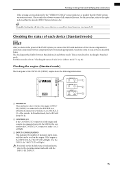
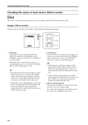
... between the engine and the console. Check the connections between engines A/B and the console, and between the DSP1D-EX {DSP1D} and the CS1D. 3 INPUT CONFIGURATION This indicates the number of monaural input channels that can be given priority. Check the CONTROL I/O connections between the console ...signals or control signals are both engines A and B blink when the power is turned on even though engines A/B are not being used with this engine. CS1D Operating Manual (Start-up) Checking the status of each device (Mirror mode) DSPx2 Here's how to check the connection status of ...
... between the engine and the console. Check the connections between engines A/B and the console, and between the DSP1D-EX {DSP1D} and the CS1D. 3 INPUT CONFIGURATION This indicates the number of monaural input channels that can be given priority. Check the CONTROL I/O connections between the console ...signals or control signals are both engines A and B blink when the power is turned on even though engines A/B are not being used with this engine. CS1D Operating Manual (Start-up) Checking the status of each device (Mirror mode) DSPx2 Here's how to check the connection status of ...

Owner's Manual
Page 30
...the PM1D system will automatically remember them. (However if you modify the configuration of the PM1D system and how the components are used to make settings again.) Be aware that the display screens and settings differ between Standard mode and Mirror mode. By pressing the same switch...] switch Hint The switches of the PM1D (which one console is what determines the system configuration and how the components are using Mirror mode, please proceed to access the screen shown on the following page. If you can successively access different screens within that will need...
...the PM1D system will automatically remember them. (However if you modify the configuration of the PM1D system and how the components are used to make settings again.) Be aware that the display screens and settings differ between Standard mode and Mirror mode. By pressing the same switch...] switch Hint The switches of the PM1D (which one console is what determines the system configuration and how the components are using Mirror mode, please proceed to access the screen shown on the following page. If you can successively access different screens within that will need...


