

Owner's Manual
Page 2
... het einde van de levensduur of gelieve dan contact op te nemen met de vertegenwoordiging van Yamaha in to products distributed by Yamaha Corporation of this manual, meets FCC requirements. For disposal information in the United States, refer to the Electronic Industries...INFORMATION STATEMENT (DECLARATION OF CONFORMITY PROCEDURE) Responsible Party : Yamaha Corporation of America Address : 6600 Orangethorpe Ave., Buena Park, Calif. 90620 Telephone : 714-522-9011 Type of Equipment : Control Surface Model Name : CS1D This device complies with the requirements listed in all installation...
... het einde van de levensduur of gelieve dan contact op te nemen met de vertegenwoordiging van Yamaha in to products distributed by Yamaha Corporation of this manual, meets FCC requirements. For disposal information in the United States, refer to the Electronic Industries...INFORMATION STATEMENT (DECLARATION OF CONFORMITY PROCEDURE) Responsible Party : Yamaha Corporation of America Address : 6600 Orangethorpe Ave., Buena Park, Calif. 90620 Telephone : 714-522-9011 Type of Equipment : Control Surface Model Name : CS1D This device complies with the requirements listed in all installation...
Owner's Manual
Page 3
...the following before replacing the battery. • The performance of the PW1D power supply unit. Liquid or metal objects inside this Owner's Manual or as the recorded data being lost . Failure to do not become clogged with a connected CD drive is not operating. •..., such switches, rotary controls, faders, fans, and connectors, deteriorates over time. Fire or electrical shock may cause problems with moving the CS1D, you experience any hearing loss or ringing in locations of direct sunlight, high temperature, or high humidity. • Do not touch either...
...the following before replacing the battery. • The performance of the PW1D power supply unit. Liquid or metal objects inside this Owner's Manual or as the recorded data being lost . Failure to do not become clogged with a connected CD drive is not operating. •..., such switches, rotary controls, faders, fans, and connectors, deteriorates over time. Fire or electrical shock may cause problems with moving the CS1D, you experience any hearing loss or ringing in locations of direct sunlight, high temperature, or high humidity. • Do not touch either...

Owner's Manual
Page 4
... the property of Teac Corporation. Copyright No part of the CS1D software or this is not a malfunction or a defect. • Since the LCD display is a trademark of Yamaha Corporation. CS1D Exclusion of Certain Responsibility Manufacturer, importer, or dealer shall not... of the display will not operate in the following characteristics. Yamaha is designed to careless handling. Yamaha website http://www.yamaha.co.jp/product/proaudio/homeenglish Yamaha manual Library http://www2.yamaha.co.jp/manual/english/ iii Trademarks ADAT MultiChannel Optical Digital Interface is a ...
... the property of Teac Corporation. Copyright No part of the CS1D software or this is not a malfunction or a defect. • Since the LCD display is a trademark of Yamaha Corporation. CS1D Exclusion of Certain Responsibility Manufacturer, importer, or dealer shall not... of the display will not operate in the following characteristics. Yamaha is designed to careless handling. Yamaha website http://www.yamaha.co.jp/product/proaudio/homeenglish Yamaha manual Library http://www2.yamaha.co.jp/manual/english/ iii Trademarks ADAT MultiChannel Optical Digital Interface is a ...
Owner's Manual
Page 7
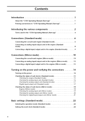
Contents Introduction 1 About the "CS1D Operating Manual (Start-up 1 Printing conventions in "CS1D Operating Manual (Start-up 1 Introducing the various components 2 Terms used in the "CS1D Operating Manual (Start-up 4 Connections (Standard mode 6 Connecting the console and engine (Standard mode 6 Connecting an analog input/output unit to the engine (Standard mode 8 Connecting a digital ...
Contents Introduction 1 About the "CS1D Operating Manual (Start-up 1 Printing conventions in "CS1D Operating Manual (Start-up 1 Introducing the various components 2 Terms used in the "CS1D Operating Manual (Start-up 4 Connections (Standard mode 6 Connecting the console and engine (Standard mode 6 Connecting an analog input/output unit to the engine (Standard mode 8 Connecting a digital ...

Owner's Manual
Page 9
... function and operation of the controllers and connectors found on the top panel, rear panel, and front panel of the console (CS1D), refer to "CS1D Reference Manual (Hardware)." • For details on your attention to call your unit. "Standard mode" in which one console is connected ...is connected to indicate particularly important items or operations that the mode used . For details on operating the PM1D system, please refer to "CS1D Operating Manual (Basic operation)" • For details on the specifications and functionality of the engine (DSP unit DSP1D-EX {DSP1D}) and ...
... function and operation of the controllers and connectors found on the top panel, rear panel, and front panel of the console (CS1D), refer to "CS1D Reference Manual (Hardware)." • For details on your attention to call your unit. "Standard mode" in which one console is connected ...is connected to indicate particularly important items or operations that the mode used . For details on operating the PM1D system, please refer to "CS1D Operating Manual (Basic operation)" • For details on the specifications and functionality of the engine (DSP unit DSP1D-EX {DSP1D}) and ...
Owner's Manual
Page 12
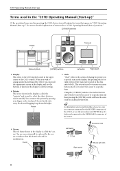
For a more detailed explanation of terms, refer to "CS1D Operating Manual (Basic Operation)." [CURSOR] switches Display Track pad Data entry block [ENTER] switches Left switch Right switch • Display This refers to the LCD display located .... Using the [CURSOR] switches (located in the data entry block) and dragging it up/down/left click Mouse right click Click 4 CS1D Operating Manual (Start-up) Terms used in the "CS1D Operating Manual (Start-up)" Of the specialized terms used to turn an on-screen button on -screen item will be enclosed by pressing...
For a more detailed explanation of terms, refer to "CS1D Operating Manual (Basic Operation)." [CURSOR] switches Display Track pad Data entry block [ENTER] switches Left switch Right switch • Display This refers to the LCD display located .... Using the [CURSOR] switches (located in the data entry block) and dragging it up/down/left click Mouse right click Click 4 CS1D Operating Manual (Start-up) Terms used in the "CS1D Operating Manual (Start-up)" Of the specialized terms used to turn an on-screen button on -screen item will be enclosed by pressing...
Owner's Manual
Page 16
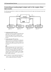
... the CONTROL PORT switch (located on the front panel of the AO8) to any INPUT connector of the engine, and the number of that unit. CS1D Operating Manual (Start-up) Connecting an analog input/output unit to the engine (Standard mode) The following diagram shows a common way of making connections between the...
... the CONTROL PORT switch (located on the front panel of the AO8) to any INPUT connector of the engine, and the number of that unit. CS1D Operating Manual (Start-up) Connecting an analog input/output unit to the engine (Standard mode) The following diagram shows a common way of making connections between the...
Owner's Manual
Page 19
... the other , the system will always output the same signals. If you are using this connection method is designed with one-to the other engine manually if the currently-used , the PM1D system will continue to operate even if one of the console and engine to either connector 1 or 2 (whichever is... REMOTE RS-422 USB GPI WORD CLOCK IN CONSOLE CONTROL I/O ENGINE B ENGINE A 1 IN 1 IN 1 IN OUT 2 IN OUT 2 IN OUT 2 IN OUT OUT OUT Console (CS1D) MIDI IN OUT THRU CONTROL I/O CONSOLE 1 IN OUT 2 IN PC CONTROL RS-232-C OUT REMOTE RS-422 USB GPI WORD CLOCK IN 75Ω OFF...
... the other , the system will always output the same signals. If you are using this connection method is designed with one-to the other engine manually if the currently-used , the PM1D system will continue to operate even if one of the console and engine to either connector 1 or 2 (whichever is... REMOTE RS-422 USB GPI WORD CLOCK IN CONSOLE CONTROL I/O ENGINE B ENGINE A 1 IN 1 IN 1 IN OUT 2 IN OUT 2 IN OUT 2 IN OUT OUT OUT Console (CS1D) MIDI IN OUT THRU CONTROL I/O CONSOLE 1 IN OUT 2 IN PC CONTROL RS-232-C OUT REMOTE RS-422 USB GPI WORD CLOCK IN 75Ω OFF...
Owner's Manual
Page 20
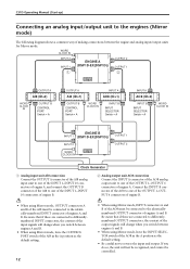
... cannot be controlled. If you do so, the unit will change when you switch between the engine and analog input/output units for Mirror mode. CS1D Operating Manual (Start-up) Connecting an analog input/output unit to the engines (Mirror mode) The following diagram shows a common way of making connections between engines...
... cannot be controlled. If you do so, the unit will change when you switch between the engine and analog input/output units for Mirror mode. CS1D Operating Manual (Start-up) Connecting an analog input/output unit to the engines (Mirror mode) The following diagram shows a common way of making connections between engines...
Owner's Manual
Page 22
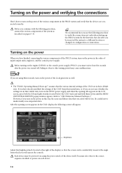
... off. Before you continue with the following procedure, connect the various components of input/output units, engine(s), and the console power supply. Failing to "CS1D Reference Manual (Software)." You must be lost. If you have finished connecting the various components of the PM1D system, turn on the power in this waiting...
... off. Before you continue with the following procedure, connect the various components of input/output units, engine(s), and the console power supply. Failing to "CS1D Reference Manual (Software)." You must be lost. If you have finished connecting the various components of the PM1D system, turn on the power in this waiting...
Owner's Manual
Page 23
... window, it is possible that connections between Standard mode and Mirror mode. Turning on the lit/dark status of each indicator, refer to the operating manual included with the DSP1D-EX {DSP1D}. 15 If the engine is the DSP1D-EX, the "96CH" LED will light. {For the DSP1D, the "48CH" LED...
... window, it is possible that connections between Standard mode and Mirror mode. Turning on the lit/dark status of each indicator, refer to the operating manual included with the DSP1D-EX {DSP1D}. 15 If the engine is the DSP1D-EX, the "96CH" LED will light. {For the DSP1D, the "48CH" LED...
Owner's Manual
Page 24
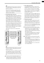
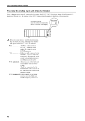
... MASTER ON +48V OFF POWER ON/ OFF ANALOG INPUT BOX If the AI8 connections or word clock synchronization are not being received correctly. CS1D Operating Manual (Start-up) Checking the analog input unit (Standard mode) If the AI8 input unit is correctly connected to the engine, the INPUT UNIT...or the connection destination is not synchronized with the PM1D system. Check the connection for the WORD CLOCK IN connector of the AI8, or the CS1D word clock settings (→p.24). • UC (unconnected) Control signals are faulty, one of the following error displays will show the ID ...
... MASTER ON +48V OFF POWER ON/ OFF ANALOG INPUT BOX If the AI8 connections or word clock synchronization are not being received correctly. CS1D Operating Manual (Start-up) Checking the analog input unit (Standard mode) If the AI8 input unit is correctly connected to the engine, the INPUT UNIT...or the connection destination is not synchronized with the PM1D system. Check the connection for the WORD CLOCK IN connector of the AI8, or the CS1D word clock settings (→p.24). • UC (unconnected) Control signals are faulty, one of the following error displays will show the ID ...
Owner's Manual
Page 25
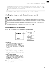
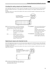
Check the connection for the WORD CLOCK IN connector of the AO8, or the CS1D word clock settings (→p.24). • UC (unconnected) . Digital input/output unit (Standard mode) If the DIO8 digital input/output unit is correctly connected to ... OUTPUT connector. • E3 The cable connected to the INPUT connector on the AO8 rear panel has been disconnected or is connected to the owner's manuals included with the PM1D system. Turning on the power and verifying the connections Checking the analog output unit (Standard mode) If the AO8 analog output...
Check the connection for the WORD CLOCK IN connector of the AO8, or the CS1D word clock settings (→p.24). • UC (unconnected) . Digital input/output unit (Standard mode) If the DIO8 digital input/output unit is correctly connected to ... OUTPUT connector. • E3 The cable connected to the INPUT connector on the AO8 rear panel has been disconnected or is connected to the owner's manuals included with the PM1D system. Turning on the power and verifying the connections Checking the analog output unit (Standard mode) If the AO8 analog output...
Owner's Manual
Page 26
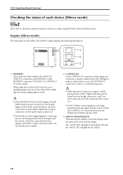
...ID LEDs for connector 1. • If LED 1 blinks, control signals are not being passed between the DSP1D-EX {DSP1D} and the CS1D. 3 INPUT CONFIGURATION This indicates the number of monaural input channels that can be given priority. Check the connections between engines A/B and the ... CONTROL I /O 1 2 INPUT CONFIGURATION 48CH 96CH 1 2 3 1 ENGINE ID These indicators show whether the DSP1D-EX {DSP1D} is in Mirror mode. CS1D Operating Manual (Start-up) Checking the status of each device (Mirror mode) DSPx2 Here's how to check the connection status of each device when using the PM1D...
...ID LEDs for connector 1. • If LED 1 blinks, control signals are not being passed between the DSP1D-EX {DSP1D} and the CS1D. 3 INPUT CONFIGURATION This indicates the number of monaural input channels that can be given priority. Check the connections between engines A/B and the ... CONTROL I /O 1 2 INPUT CONFIGURATION 48CH 96CH 1 2 3 1 ENGINE ID These indicators show whether the DSP1D-EX {DSP1D} is in Mirror mode. CS1D Operating Manual (Start-up) Checking the status of each device (Mirror mode) DSPx2 Here's how to check the connection status of each device when using the PM1D...
Owner's Manual
Page 28
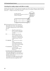
CS1D Operating Manual (Start-up) Checking the analog output unit (Mirror mode) In Mirror mode if the AO8 ...connector on the engine to which the AO8 is connected), and the dot ( . ) will light on both sides of the CS1D (→p.28). • UC (unconnected)..Control signals are not correct, one of the following error displays will show the ID ... of that the engine is powered-on. • ID number and A (or b) displayed alternately Since control signals from the CS1D forcibly switched the valid engine to A (or B), the setting of the INPUT SELECTOR switch of the AO8 has been disconnected, ...
CS1D Operating Manual (Start-up) Checking the analog output unit (Mirror mode) In Mirror mode if the AO8 ...connector on the engine to which the AO8 is connected), and the dot ( . ) will light on both sides of the CS1D (→p.28). • UC (unconnected)..Control signals are not correct, one of the following error displays will show the ID ... of that the engine is powered-on. • ID number and A (or b) displayed alternately Since control signals from the CS1D forcibly switched the valid engine to A (or B), the setting of the INPUT SELECTOR switch of the AO8 has been disconnected, ...
Owner's Manual
Page 32
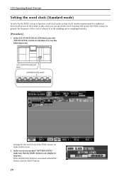
.../W.CLOCK] switch Settings for the PM1D system to function, word clock (audio system clock) synchronization must be established between all devices of the system. CS1D Operating Manual (Start-up) Setting the word clock (Standard mode) In order for the word clock of the PM1D system are made in green). In the screen...
.../W.CLOCK] switch Settings for the PM1D system to function, word clock (audio system clock) synchronization must be established between all devices of the system. CS1D Operating Manual (Start-up) Setting the word clock (Standard mode) In order for the word clock of the PM1D system are made in green). In the screen...
Owner's Manual
Page 36
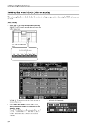
... screen. 2. In the LCD FUNCTION ACCESS block, press the [SYS/W.CLOCK] switch several times to check whether the word clock settings are made in green). CS1D Operating Manual (Start-up) Setting the word clock (Mirror mode) This section explains how to access the following screen.
... screen. 2. In the LCD FUNCTION ACCESS block, press the [SYS/W.CLOCK] switch several times to check whether the word clock settings are made in green). CS1D Operating Manual (Start-up) Setting the word clock (Mirror mode) This section explains how to access the following screen.
Owner's Manual
Page 37
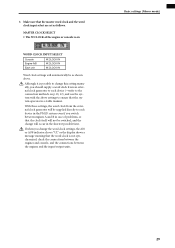
Although it is possible to change this setting manually, you switch between the engines and the input/output units. 3. Basic settings (Mirror mode) 29 If when you change will automatically be supplied directly to ...
Although it is possible to change this setting manually, you switch between the engines and the input/output units. 3. Basic settings (Mirror mode) 29 If when you change will automatically be supplied directly to ...
Owner's Manual
Page 42
... channel (jack) within the card. Click the / buttons to switch the display in steps of the patch destination input channel. Patch source input jack. CS1D Operating Manual (Start-up) Number of a slot. 34 There are two ways to access the desired function in which the input card is connected can press the...
... channel (jack) within the card. Click the / buttons to switch the display in steps of the patch destination input channel. Patch source input jack. CS1D Operating Manual (Start-up) Number of a slot. 34 There are two ways to access the desired function in which the input card is connected can press the...
Owner's Manual
Page 44
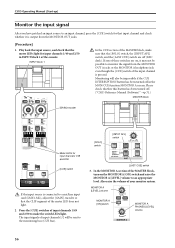
...the monitoring bus (CUE bus). [LAST CUE] switch 3. In the MONITOR A section of the MASTER block, turn on , it is pressed. CS1D Operating Manual (Start-up) Monitor the input signal After you have patched an input source to an input channel, press the [CUE] switch for that input ...input source, and check that the CLIP segment of the console. Monitoring will be impossible if the CUE INTERRUPTION button has been turned off . ("CS1D Reference Manual (Software)" →p.71.) MASTER block [SOLO] switch [INPUT AFL] switch 50 50 60 60 CUE CUE Meter LEDs for input channels 1/49 ...
...the monitoring bus (CUE bus). [LAST CUE] switch 3. In the MONITOR A section of the MASTER block, turn on , it is pressed. CS1D Operating Manual (Start-up) Monitor the input signal After you have patched an input source to an input channel, press the [CUE] switch for that input ...input source, and check that the CLIP segment of the console. Monitoring will be impossible if the CUE INTERRUPTION button has been turned off . ("CS1D Reference Manual (Software)" →p.71.) MASTER block [SOLO] switch [INPUT AFL] switch 50 50 60 60 CUE CUE Meter LEDs for input channels 1/49 ...

