

Owner's Manual
Page 1
E POWER AMPLIFIER Owner's Manual POWER TEMP PROTECTION POWER ON OFF POWER AMPLIFIER 20 15 L CLIP R 20 15 25 10 25 10 30 LEVEL 30 6 6 40 3 40 3 0 L -dB 0 R Keep This Manual For Future Reference.
E POWER AMPLIFIER Owner's Manual POWER TEMP PROTECTION POWER ON OFF POWER AMPLIFIER 20 15 L CLIP R 20 15 25 10 25 10 30 LEVEL 30 6 6 40 3 40 3 0 L -dB 0 R Keep This Manual For Future Reference.
Owner's Manual
Page 3
... turn it off , remove the power plug from the AC outlet, and contact your dealer for a replacement. Using the unit in this Owner's Manual or as smoke, odor, or noise, or if a foreign object or liquid gets inside the unit, turn the power switch off immediately. Cautions ...notice any purpose other types of cables is necessary, contact your dealer for normal ventilation. Using other than driving loudspeakers. CP2000-Owner's Manual If you continue using the CP2000 Warnings • Do not allow water to enter this unit or allow enough free space around the unit for repair. ...
... turn it off , remove the power plug from the AC outlet, and contact your dealer for a replacement. Using the unit in this Owner's Manual or as smoke, odor, or noise, or if a foreign object or liquid gets inside the unit, turn the power switch off immediately. Cautions ...notice any purpose other types of cables is necessary, contact your dealer for normal ventilation. Using other than driving loudspeakers. CP2000-Owner's Manual If you continue using the CP2000 Warnings • Do not allow water to enter this unit or allow enough free space around the unit for repair. ...
Owner's Manual
Page 4
... 14 Specifications 14 Dimensions 15 Block Diagram 16 CP2000-Owner's Manual All other trademarks are the property of Yamaha Corporation. ii Contents Package Contents The CP2000 package should contain the following items. Contact your Yamaha dealer if anything is missing. • CP2000 Power Amplifier • This manual Trademarks Yamaha is a trademark of their respective holders and...
... 14 Specifications 14 Dimensions 15 Block Diagram 16 CP2000-Owner's Manual All other trademarks are the property of Yamaha Corporation. ii Contents Package Contents The CP2000 package should contain the following items. Contact your Yamaha dealer if anything is missing. • CP2000 Power Amplifier • This manual Trademarks Yamaha is a trademark of their respective holders and...
Owner's Manual
Page 5
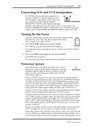
... system protects both amplifier and speakers if heatsink overheating occurs or a DC offset is idle, the fan stops for choosing the Yamaha CP2000 Power Amplifier. CP2000 key features include • 650 W+650 W into 4Ω stereo, 450 W+450 W into 8Ω stereo. • 2,000 W ...-channel power amplifier, offering high-power, superb sonic performance, and reliability, all backed by up to the Yamaha S115 and S112 loud- CP2000-Owner's Manual speakers. • Three operating modes are provided: STEREO mode in which Channel L and Channel R operate independently, PARALLEL...
... system protects both amplifier and speakers if heatsink overheating occurs or a DC offset is idle, the fan stops for choosing the Yamaha CP2000 Power Amplifier. CP2000 key features include • 650 W+650 W into 4Ω stereo, 450 W+450 W into 8Ω stereo. • 2,000 W ...-channel power amplifier, offering high-power, superb sonic performance, and reliability, all backed by up to the Yamaha S115 and S112 loud- CP2000-Owner's Manual speakers. • Three operating modes are provided: STEREO mode in which Channel L and Channel R operate independently, PARALLEL...
Owner's Manual
Page 6
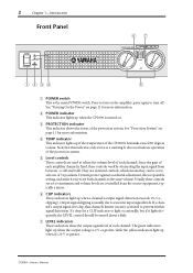
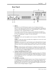
...input signal from the source equipment, typically a mixer. G LEVEL indicators These indicators show the output signal level of the CP2000's heatsinks exceed 85 degrees Celsius. CP2000-Owner's Manual D TEMP indicator This indicator lights up when a channel's output signal distortion exceeds 1% (i.e., clipping). It's okay for .... The green indicators light up when the output voltage is 2 V or greater, while the yellow indicators light up when the CP2000 is fixed, these controls are detented controls, which means they can be turned down a little. B POWER indicator This ...
...input signal from the source equipment, typically a mixer. G LEVEL indicators These indicators show the output signal level of the CP2000's heatsinks exceed 85 degrees Celsius. CP2000-Owner's Manual D TEMP indicator This indicator lights up when a channel's output signal distortion exceeds 1% (i.e., clipping). It's okay for .... The green indicators light up when the output voltage is 2 V or greater, while the yellow indicators light up when the CP2000 is fixed, these controls are detented controls, which means they can be turned down a little. B POWER indicator This ...
Owner's Manual
Page 7
...using the Channel L LEVEL control, and the speakers are connected to another amplifier. This mode is typically used with the Yamaha S115 and S112 loudspeakers. When other speakers are electronically balanced, although they can be used to OFF. The 1/4" phone jacks accept ...1/4" phone plugs, while the 5-way binding posts offer several methods of speakers. CP2000-Owner's Manual See "Connecting Inputs" on page 7 for more information. See "Daisy Chaining Inputs" on page 11 for more information. See "Connecting ...
...using the Channel L LEVEL control, and the speakers are connected to another amplifier. This mode is typically used with the Yamaha S115 and S112 loudspeakers. When other speakers are electronically balanced, although they can be used to OFF. The 1/4" phone jacks accept ...1/4" phone plugs, while the 5-way binding posts offer several methods of speakers. CP2000-Owner's Manual See "Connecting Inputs" on page 7 for more information. See "Daisy Chaining Inputs" on page 11 for more information. See "Connecting ...
Owner's Manual
Page 8
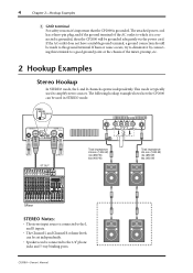
... YAMAHA SPEAKER PROCESSING 2 1 1 2 CHANNEL R (-) BRIDGE (+) SPEAKERS CHANNEL L or ST OUT Total impedance: 2Ω min (1000 W) 4Ω (650 W) 8Ω (450 W) Total impedance: 2Ω min (1000 W) 4Ω (650 W) 8Ω (450 W) Mixer STEREO Notes: • The stereo input source is typically used in STEREO mode. CP2000-Owner's Manual If...jacks and 5-way binding posts. If hum or noise occurs, try to eliminate it 's important that the CP2000 is grounded, then the CP2000 will be used to which it is connected is grounded. The attached power cord has a three-pin plug,...
... YAMAHA SPEAKER PROCESSING 2 1 1 2 CHANNEL R (-) BRIDGE (+) SPEAKERS CHANNEL L or ST OUT Total impedance: 2Ω min (1000 W) 4Ω (650 W) 8Ω (450 W) Total impedance: 2Ω min (1000 W) 4Ω (650 W) 8Ω (450 W) Mixer STEREO Notes: • The stereo input source is typically used in STEREO mode. CP2000-Owner's Manual If...jacks and 5-way binding posts. If hum or noise occurs, try to eliminate it 's important that the CP2000 is grounded, then the CP2000 will be used to which it is connected is grounded. The attached power cord has a three-pin plug,...
Owner's Manual
Page 9
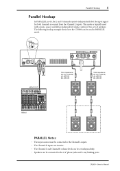
CP2000-Owner's Manual The following hookup example shows how the CP2000 can be used with a mono source and allows independent volume control of two sets of speakers. Parallel Hookup 5 Parallel Hookup... the input signal for both channels is typically used in PARALLEL mode. STEREO BRIDGE PARALLEL CHANNEL R 2 1 3 INPUT STEREO BRIDGE PARALLEL OFF ON CHANNEL L (BRIDGE) NEUTRIK 2 1 3 YAMAHA SPEAKER PROCESSING MONO OUT 2 1 1 2 CHANNEL R (-) BRIDGE (+) SPEAKERS CHANNEL L Total impedance: 2Ω min (1000 W) 4Ω (650 W) 8Ω (450 W) Total impedance: 2Ω min...
CP2000-Owner's Manual The following hookup example shows how the CP2000 can be used with a mono source and allows independent volume control of two sets of speakers. Parallel Hookup 5 Parallel Hookup... the input signal for both channels is typically used in PARALLEL mode. STEREO BRIDGE PARALLEL CHANNEL R 2 1 3 INPUT STEREO BRIDGE PARALLEL OFF ON CHANNEL L (BRIDGE) NEUTRIK 2 1 3 YAMAHA SPEAKER PROCESSING MONO OUT 2 1 1 2 CHANNEL R (-) BRIDGE (+) SPEAKERS CHANNEL L Total impedance: 2Ω min (1000 W) 4Ω (650 W) 8Ω (450 W) Total impedance: 2Ω min...
Owner's Manual
Page 10
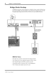
...CP2000-Owner's Manual The input signal is set by using the Channel L LEVEL control. • The Channel R inputs and LEVEL control are combined to the 5-way binding posts. • The 1/4" phone jack outputs must not be used in BRIDGE mode. The following hookup example shows how the CP2000... can be used . STEREO BRIDGE PARALLEL CHANNEL R 2 1 3 INPUT STEREO BRIDGE PARALLEL OFF ON CHANNEL L (BRIDGE) NEUTRIK 2 1 3 YAMAHA SPEAKER PROCESSING 2 1 1 2 CHANNEL R (-) BRIDGE (+) SPEAKERS CHANNEL L...
...CP2000-Owner's Manual The input signal is set by using the Channel L LEVEL control. • The Channel R inputs and LEVEL control are combined to the 5-way binding posts. • The 1/4" phone jack outputs must not be used in BRIDGE mode. The following hookup example shows how the CP2000... can be used . STEREO BRIDGE PARALLEL CHANNEL R 2 1 3 INPUT STEREO BRIDGE PARALLEL OFF ON CHANNEL L (BRIDGE) NEUTRIK 2 1 3 YAMAHA SPEAKER PROCESSING 2 1 1 2 CHANNEL R (-) BRIDGE (+) SPEAKERS CHANNEL L...
Owner's Manual
Page 11
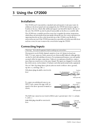
...the covers before making any way. The inputs are wired as follows: pin 1-ground, pin 2-hot (+), and pin 3-cold (-). 3 Using the CP2000 Using the CP2000 7 Installation The CP2000 can be mounted in any connections. Under no circumstances should be sure to the rear of one 1/4" phone jack and one sound source... jacks are designed to the sleeve (ground) terminal, as mixers, CD players, and other professional audio equipment. Male XLR plug 1 (ground) 3 (cold) 2 (hot) CP2000-Owner's Manual The CP2000 uses a variable-speed low-noise fan to the same channel.
...the covers before making any way. The inputs are wired as follows: pin 1-ground, pin 2-hot (+), and pin 3-cold (-). 3 Using the CP2000 Using the CP2000 7 Installation The CP2000 can be mounted in any connections. Under no circumstances should be sure to the rear of one 1/4" phone jack and one sound source... jacks are designed to the sleeve (ground) terminal, as mixers, CD players, and other professional audio equipment. Male XLR plug 1 (ground) 3 (cold) 2 (hot) CP2000-Owner's Manual The CP2000 uses a variable-speed low-noise fan to the same channel.
Owner's Manual
Page 12
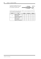
Channel R L Item INPUT connectors LEVEL control Signal & CLIP indicators INPUT connectors LEVEL control Signal & CLIP indicators STEREO O O O O O O PARALLEL X O O O O O BRIDGE X X O O O O CP2000-Owner's Manual 8 Chapter 3-Using the CP2000 To connect an unbalanced source to an INPUT XLR, connect pin 3 (cold) to pin 1 (ground), as shown below. Male XLR plug 1 (ground) 3 (cold) 2 (hot) The following table shows which inputs, LEVEL controls, and signal and CLIP indicators are active in each CP2000 mode.
Channel R L Item INPUT connectors LEVEL control Signal & CLIP indicators INPUT connectors LEVEL control Signal & CLIP indicators STEREO O O O O O O PARALLEL X O O O O O BRIDGE X X O O O O CP2000-Owner's Manual 8 Chapter 3-Using the CP2000 To connect an unbalanced source to an INPUT XLR, connect pin 3 (cold) to pin 1 (ground), as shown below. Male XLR plug 1 (ground) 3 (cold) 2 (hot) The following table shows which inputs, LEVEL controls, and signal and CLIP indicators are active in each CP2000 mode.
Owner's Manual
Page 13
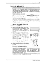
...with a suitable power rat- 1/4" phone plug ing. When attaching speaker cables with the correct polarity, otherwise, the sound qual- Caution for each CP2000 channel comprise of one 1/4" phone jack and one pair of the bare wires are splayed in such a way that they may cause a short... the binding posts, place the spade lugs on the speaker must be affected. Sleeve (-) When connecting to the binding post labelled (-). CP2000-Owner's Manual The outputs for Speaker Connection 1 Turn off about 15 mm of connection, including single or double banana plugs, spade lugs, or bare...
...with a suitable power rat- 1/4" phone plug ing. When attaching speaker cables with the correct polarity, otherwise, the sound qual- Caution for each CP2000 channel comprise of one 1/4" phone jack and one pair of the bare wires are splayed in such a way that they may cause a short... the binding posts, place the spade lugs on the speaker must be affected. Sleeve (-) When connecting to the binding post labelled (-). CP2000-Owner's Manual The outputs for Speaker Connection 1 Turn off about 15 mm of connection, including single or double banana plugs, spade lugs, or bare...
Owner's Manual
Page 14
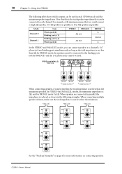
...speakers to a channel's 1/4" phone jack and binding posts simultaneously, so long as shown in each channel. CP2000-Owner's Manual 10 Chapter 3-Using the CP2000 The following examples. When connecting multiple speaker cabinets, make sure the total impedance is not less than the ...used . In STEREO and PARALLEL modes, the minimum impedance is not less than the minimum. In BRIDGE mode, the speakers must be connected to each CP2000 mode and the minimum speaker impedance. When speakers are connected in parallel. Total = 2Ω Total = 4Ω Total = 2Ω 8Ω...
...speakers to a channel's 1/4" phone jack and binding posts simultaneously, so long as shown in each channel. CP2000-Owner's Manual 10 Chapter 3-Using the CP2000 The following examples. When connecting multiple speaker cabinets, make sure the total impedance is not less than the ...used . In STEREO and PARALLEL modes, the minimum impedance is not less than the minimum. In BRIDGE mode, the speakers must be connected to each CP2000 mode and the minimum speaker impedance. When speakers are connected in parallel. Total = 2Ω Total = 4Ω Total = 2Ω 8Ω...
Owner's Manual
Page 15
... indicator lights up . Another layer of time, the thermostatic cutout CP2000-Owner's Manual ON OFF The output relay closes, connecting the speakers, several seconds after the CP2000 is turned off the CP2000. When the CP2000 is turned on. 2 Press the [POWER] switch again to turn...speakers, the PROTECTION indicator goes out, and normal operation is active, the speakers are disconnected from the CP2000 and the PROTECTION indicator lights up . Yamaha loudspeakers should be set to abnormal operating conditions. When the protection system is resumed. During this order...
... indicator lights up . Another layer of time, the thermostatic cutout CP2000-Owner's Manual ON OFF The output relay closes, connecting the speakers, several seconds after the CP2000 is turned off the CP2000. When the CP2000 is turned on. 2 Press the [POWER] switch again to turn...speakers, the PROTECTION indicator goes out, and normal operation is active, the speakers are disconnected from the CP2000 and the PROTECTION indicator lights up . Yamaha loudspeakers should be set to abnormal operating conditions. When the protection system is resumed. During this order...
Owner's Manual
Page 16
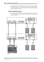
... POWER indicator goes out. CHANNEL R 2 1 3 INPUT STEREO BRIDGE PARALLEL OFF ON CHANNEL L (BRIDGE) NEUTRIK 2 1 3 YAMAHA SPEAKER PROCESSING 2 1 1 2 CHANNEL R (-) BRIDGE (+) SPEAKERS CHANNEL L CHANNEL R 2 1 3 INPUT STEREO BRIDGE PARALLEL OFF ON CHANNEL L (BRIDGE) NEUTRIK 2 1 3 YAMAHA SPEAKER PROCESSING ST OUT Mixer CP2000-Owner's Manual 2 1 1 2 CHANNEL R (-) BRIDGE (+) SPEAKERS CHANNEL L Daisy Chaining Inputs Since the phone jack and XLR-type...
... POWER indicator goes out. CHANNEL R 2 1 3 INPUT STEREO BRIDGE PARALLEL OFF ON CHANNEL L (BRIDGE) NEUTRIK 2 1 3 YAMAHA SPEAKER PROCESSING 2 1 1 2 CHANNEL R (-) BRIDGE (+) SPEAKERS CHANNEL L CHANNEL R 2 1 3 INPUT STEREO BRIDGE PARALLEL OFF ON CHANNEL L (BRIDGE) NEUTRIK 2 1 3 YAMAHA SPEAKER PROCESSING ST OUT Mixer CP2000-Owner's Manual 2 1 1 2 CHANNEL R (-) BRIDGE (+) SPEAKERS CHANNEL L Daisy Chaining Inputs Since the phone jack and XLR-type...
Owner's Manual
Page 17
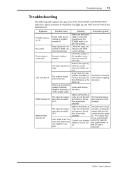
...clipping distortion. Remedy Protection System Make sure the power cable is connected properly and the POWER switch is too high. Contact your Yamaha dealer or service center. Ensure that the total speaker impedance is removed. Make sure that the air vents are not blocked ... air vents are not blocked and improve the airflow around the amplifier. Locate and remove the short. CP2000-Owner's Manual The protection circuit activates, opening the output relay and disconnecting the speakers. Troubleshooting 13 Troubleshooting The following table explains the operation ...
...clipping distortion. Remedy Protection System Make sure the power cable is connected properly and the POWER switch is too high. Contact your Yamaha dealer or service center. Ensure that the total speaker impedance is removed. Make sure that the air vents are not blocked ... air vents are not blocked and improve the airflow around the amplifier. Locate and remove the short. CP2000-Owner's Manual The protection circuit activates, opening the output relay and disconnecting the speakers. Troubleshooting 13 Troubleshooting The following table explains the operation ...
Owner's Manual
Page 18
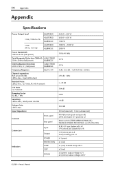
... +4 dB 33.8 dB 30 kΩ (balanced), 15 kΩ (unbalanced) POWER switch (push on/push off) LEVEL attenuator (31 position) x2 Mode switch (STEREO/BRIDGE/PARALLEL) YAMAHA SPEAKER PROCESSING switch (ON/OFF) XLR-3-31 type (balanced) L+R 1/4" phone jack (balanced) L+R 1/4" phone jack L+R 5-way binding post x1 x1 (green) x1 (red) x1 (red) heatsink...
... +4 dB 33.8 dB 30 kΩ (balanced), 15 kΩ (unbalanced) POWER switch (push on/push off) LEVEL attenuator (31 position) x2 Mode switch (STEREO/BRIDGE/PARALLEL) YAMAHA SPEAKER PROCESSING switch (ON/OFF) XLR-3-31 type (balanced) L+R 1/4" phone jack (balanced) L+R 1/4" phone jack L+R 5-way binding post x1 x1 (green) x1 (red) x1 (red) heatsink...
Owner's Manual
Page 19
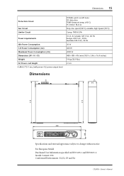
... 416 410 88 480 Specifications and external appearance subject to change without notice. Inrush Current: 65A Conformed Environment: E1, E2, E3 and E4 CP2000-Owner's Manual
... 416 410 88 480 Specifications and external appearance subject to change without notice. Inrush Current: 65A Conformed Environment: E1, E2, E3 and E4 CP2000-Owner's Manual


