
Owner's Manual
Page 5
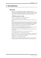
... W+450 W into 8Ω stereo. • 2,000 W into 4Ω bridged, 1,300 W into 8Ω bridged. • Yamaha Speaker Processing matches the CP2000 to 35%. • Built-in professional audio. Based on a new improved version of Yamaha's EEEngine amplifier technology, the CP2000 is a versatile two-channel power amplifier, offering high-power, superb sonic performance...
... W+450 W into 8Ω stereo. • 2,000 W into 4Ω bridged, 1,300 W into 8Ω bridged. • Yamaha Speaker Processing matches the CP2000 to 35%. • Built-in professional audio. Based on a new improved version of Yamaha's EEEngine amplifier technology, the CP2000 is a versatile two-channel power amplifier, offering high-power, superb sonic performance...
Owner's Manual
Page 7
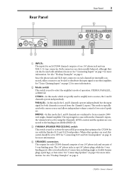
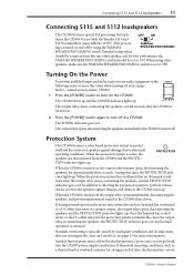
... from the Channel L inputs, the volume level is typically used with the Yamaha S115 and S112 loudspeakers. STEREO-In this mode, which is used to activate the special EQ processing that optimizes the CP2000 for use with a mono source and allows independent volume control of two sets... of operation: STEREO, PARALLEL, or BRIDGE. C YAMAHA SPEAKER PROCESSING switch This switch is typically used to select the amplifi...
... from the Channel L inputs, the volume level is typically used with the Yamaha S115 and S112 loudspeakers. STEREO-In this mode, which is used to activate the special EQ processing that optimizes the CP2000 for use with a mono source and allows independent volume control of two sets... of operation: STEREO, PARALLEL, or BRIDGE. C YAMAHA SPEAKER PROCESSING switch This switch is typically used to select the amplifi...
Owner's Manual
Page 8
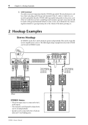
... can be set independently. • Speakers can be used to which it is connected is grounded. CP2000-Owner's Manual STEREO BRIDGE PARALLEL CHANNEL R 2 1 3 INPUT STEREO BRIDGE PARALLEL OFF ON CHANNEL L (BRIDGE) NEUTRIK 2 1 3 YAMAHA SPEAKER PROCESSING 2 1 1 2 CHANNEL R (-) BRIDGE (+) SPEAKERS CHANNEL L or ST OUT Total impedance: ...5-way binding posts. 4 Chapter 2-Hookup Examples E GND terminal For safety reasons it's important that the CP2000 is grounded, then the CP2000 will be grounded adequately via the power cord. The attached power cord has a three-pin plug, and...
... can be set independently. • Speakers can be used to which it is connected is grounded. CP2000-Owner's Manual STEREO BRIDGE PARALLEL CHANNEL R 2 1 3 INPUT STEREO BRIDGE PARALLEL OFF ON CHANNEL L (BRIDGE) NEUTRIK 2 1 3 YAMAHA SPEAKER PROCESSING 2 1 1 2 CHANNEL R (-) BRIDGE (+) SPEAKERS CHANNEL L or ST OUT Total impedance: ...5-way binding posts. 4 Chapter 2-Hookup Examples E GND terminal For safety reasons it's important that the CP2000 is grounded, then the CP2000 will be grounded adequately via the power cord. The attached power cord has a three-pin plug, and...
Owner's Manual
Page 9
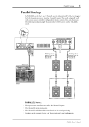
.... The following hookup example shows how the CP2000 can be used with a mono source and allows independent volume control of two sets of speakers. STEREO BRIDGE PARALLEL CHANNEL R 2 1 3 INPUT STEREO BRIDGE PARALLEL OFF ON CHANNEL L (BRIDGE) NEUTRIK 2 1 3 YAMAHA SPEAKER PROCESSING MONO OUT 2 1 1 2 CHANNEL ...volume levels can be set independently. • Speakers can be connected to the 1/4" phone jacks and 5-way binding posts. CP2000-Owner's Manual Parallel Hookup 5 Parallel Hookup In PARALLEL mode, the L and R channels operate independently but the input signal ...
.... The following hookup example shows how the CP2000 can be used with a mono source and allows independent volume control of two sets of speakers. STEREO BRIDGE PARALLEL CHANNEL R 2 1 3 INPUT STEREO BRIDGE PARALLEL OFF ON CHANNEL L (BRIDGE) NEUTRIK 2 1 3 YAMAHA SPEAKER PROCESSING MONO OUT 2 1 1 2 CHANNEL ...volume levels can be set independently. • Speakers can be connected to the 1/4" phone jacks and 5-way binding posts. CP2000-Owner's Manual Parallel Hookup 5 Parallel Hookup In PARALLEL mode, the L and R channels operate independently but the input signal ...
Owner's Manual
Page 10
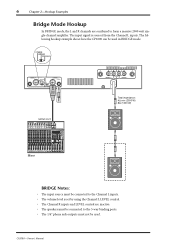
... must be connected to form a massive 2000 watt single-channel amplifier. The following hookup example shows how the CP2000 can be used in BRIDGE mode. The input signal is set by using the Channel L LEVEL control. • The... volume level is sourced from the Channel L inputs. STEREO BRIDGE PARALLEL CHANNEL R 2 1 3 INPUT STEREO BRIDGE PARALLEL OFF ON CHANNEL L (BRIDGE) NEUTRIK 2 1 3 YAMAHA SPEAKER PROCESSING 2 1 1 2 CHANNEL R (-) BRIDGE (+) SPEAKERS CHANNEL L Total impedance: 4Ω min (2000 W) 8Ω (1300 W) MONO OUT Mixer BRIDGE Notes: •...
... must be connected to form a massive 2000 watt single-channel amplifier. The following hookup example shows how the CP2000 can be used in BRIDGE mode. The input signal is set by using the Channel L LEVEL control. • The... volume level is sourced from the Channel L inputs. STEREO BRIDGE PARALLEL CHANNEL R 2 1 3 INPUT STEREO BRIDGE PARALLEL OFF ON CHANNEL L (BRIDGE) NEUTRIK 2 1 3 YAMAHA SPEAKER PROCESSING 2 1 1 2 CHANNEL R (-) BRIDGE (+) SPEAKERS CHANNEL L Total impedance: 4Ω min (2000 W) 8Ω (1300 W) MONO OUT Mixer BRIDGE Notes: •...
Owner's Manual
Page 15
...disconnecting the speakers, and the PROTECTION indicator lights up. When using the YAMAHA YAMAHA SPEAKER PROCESSING SPEAKER PROCESSING switch. ON OFF The output relay closes, connecting the speakers, several seconds after the CP2000 is typically caused by inadequate ventilation and it (see page 13 for ...When the protection system is offered by using other speaker, and for best performance the YAMAHA SPEAKER PROCESSING switch should be set to abnormal operating conditions. When the CP2000 is turned on , the output relay remains open, disconnecting the speakers, for more ...
...disconnecting the speakers, and the PROTECTION indicator lights up. When using the YAMAHA YAMAHA SPEAKER PROCESSING SPEAKER PROCESSING switch. ON OFF The output relay closes, connecting the speakers, several seconds after the CP2000 is typically caused by inadequate ventilation and it (see page 13 for ...When the protection system is offered by using other speaker, and for best performance the YAMAHA SPEAKER PROCESSING switch should be set to abnormal operating conditions. When the CP2000 is turned on , the output relay remains open, disconnecting the speakers, for more ...
Owner's Manual
Page 16
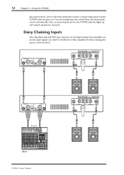
...2 1 3 INPUT STEREO BRIDGE PARALLEL OFF ON CHANNEL L (BRIDGE) NEUTRIK 2 1 3 YAMAHA SPEAKER PROCESSING 2 1 1 2 CHANNEL R (-) BRIDGE (+) SPEAKERS CHANNEL L CHANNEL R 2 1 3 INPUT STEREO BRIDGE PARALLEL OFF ON CHANNEL L (BRIDGE) NEUTRIK 2 1 3 YAMAHA SPEAKER PROCESSING ST OUT Mixer CP2000-Owner's Manual 2 1 1 2 CHANNEL R (-) BRIDGE (+) SPEAKERS CHANNEL L Daisy Chaining Inputs... lights up, and normal operation is resumed. 12 Chapter 3-Using the CP2000 disconnects the AC power when the transformer reaches a certain temperature and the POWER indicator goes out.
...2 1 3 INPUT STEREO BRIDGE PARALLEL OFF ON CHANNEL L (BRIDGE) NEUTRIK 2 1 3 YAMAHA SPEAKER PROCESSING 2 1 1 2 CHANNEL R (-) BRIDGE (+) SPEAKERS CHANNEL L CHANNEL R 2 1 3 INPUT STEREO BRIDGE PARALLEL OFF ON CHANNEL L (BRIDGE) NEUTRIK 2 1 3 YAMAHA SPEAKER PROCESSING ST OUT Mixer CP2000-Owner's Manual 2 1 1 2 CHANNEL R (-) BRIDGE (+) SPEAKERS CHANNEL L Daisy Chaining Inputs... lights up, and normal operation is resumed. 12 Chapter 3-Using the CP2000 disconnects the AC power when the transformer reaches a certain temperature and the POWER indicator goes out.
Owner's Manual
Page 18
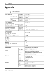
... +4 dB 33.8 dB 30 kΩ (balanced), 15 kΩ (unbalanced) POWER switch (push on/push off) LEVEL attenuator (31 position) x2 Mode switch (STEREO/BRIDGE/PARALLEL) YAMAHA SPEAKER PROCESSING switch (ON/OFF) XLR-3-31 type (balanced) L+R 1/4" phone jack (balanced) L+R 1/4" phone jack L+R 5-way binding post x1 x1 (green) x1 (red) x1 (red) heatsink temp...
... +4 dB 33.8 dB 30 kΩ (balanced), 15 kΩ (unbalanced) POWER switch (push on/push off) LEVEL attenuator (31 position) x2 Mode switch (STEREO/BRIDGE/PARALLEL) YAMAHA SPEAKER PROCESSING switch (ON/OFF) XLR-3-31 type (balanced) L+R 1/4" phone jack (balanced) L+R 1/4" phone jack L+R 5-way binding post x1 x1 (green) x1 (red) x1 (red) heatsink temp...
Owner's Manual
Page 20
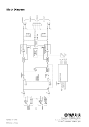
Box 3, Hamamatsu, 430-8651, Japan V617350 R1 1 IP 20 NP Printed in Taiwan CHANNEL L (BRIDGE) (PARALLEL) INPUT CHANNEL R BA CHANNEL L ATT • ON • OFF INV YAMAHA SPEAKER PROCESSING BA CHANNEL ATT R PARALLEL BRIDGE • ON • OFF STEREO POWER POWER CIRCUIT POWER SW Limiter Lch Power Amp CLIP Temperature Sensor (Heat Sink) Protection Circuit CLIP SIGNAL PROTECTION TEMP SIGNAL Limiter Rch Power Amp +B E -B +24 E -24 FAN SPEAKERS CHANNEL L L+R BRIDGE CHANNEL R Block Diagram YAMAHA CORPORATION Pro Audio & Digital Musical Instrument Division P.O.
Box 3, Hamamatsu, 430-8651, Japan V617350 R1 1 IP 20 NP Printed in Taiwan CHANNEL L (BRIDGE) (PARALLEL) INPUT CHANNEL R BA CHANNEL L ATT • ON • OFF INV YAMAHA SPEAKER PROCESSING BA CHANNEL ATT R PARALLEL BRIDGE • ON • OFF STEREO POWER POWER CIRCUIT POWER SW Limiter Lch Power Amp CLIP Temperature Sensor (Heat Sink) Protection Circuit CLIP SIGNAL PROTECTION TEMP SIGNAL Limiter Rch Power Amp +B E -B +24 E -24 FAN SPEAKERS CHANNEL L L+R BRIDGE CHANNEL R Block Diagram YAMAHA CORPORATION Pro Audio & Digital Musical Instrument Division P.O.