
Owner's Manual
Page 6
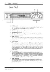
... the input signal from the source equipment, typically a mixer. If a channel's output signal does clip, that this indicator only serves as a warning. CP2000-Owner's Manual See "Turning On the Power" on page 11 for a CLIP indicator to light occasionally, but if it easy to set to the same... volume. Note that channel's limiter circuit is the main POWER switch. Output signal clipping is turned on the amplifier; C PROTECTION indicator This indicator shows the status of each ...
... the input signal from the source equipment, typically a mixer. If a channel's output signal does clip, that this indicator only serves as a warning. CP2000-Owner's Manual See "Turning On the Power" on page 11 for a CLIP indicator to light occasionally, but if it easy to set to the same... volume. Note that channel's limiter circuit is the main POWER switch. Output signal clipping is turned on the amplifier; C PROTECTION indicator This indicator shows the status of each ...
Owner's Manual
Page 17
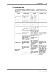
... is too high. Reduce the input signal level, or turn down . Ensure that 2Ω (STEREO/PARALLEL) or 4Ω (BRIDGE). - - - CP2000-Owner's Manual The speaker impedance is in the ON position. Make sure that the air vents are not blocked and improve the airflow... or in which they may light up, and what action to take if and when they do. The limiter circuit prevents further clipping distortion. Contact your Yamaha dealer or service center. Incorrect speaker polarity. Remedy Protection System Make sure the power cable is connected properly and the...
... is too high. Reduce the input signal level, or turn down . Ensure that 2Ω (STEREO/PARALLEL) or 4Ω (BRIDGE). - - - CP2000-Owner's Manual The speaker impedance is in the ON position. Make sure that the air vents are not blocked and improve the airflow... or in which they may light up, and what action to take if and when they do. The limiter circuit prevents further clipping distortion. Contact your Yamaha dealer or service center. Incorrect speaker polarity. Remedy Protection System Make sure the power cable is connected properly and the...
Owner's Manual
Page 19
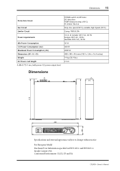
For European Model Purchaser/User Information specified in EN55103-1 and EN55103-2. Inrush Current: 65A Conformed Environment: E1, E2, E3 and E4 CP2000-Owner's Manual Dimensions 15 Protection Circuit Fan Circuit Limiter Circuit Power requirements Idle Power Consumption 1/8 Power Consumption (4Ω) Maximum Power Consumption (4Ω) Dimensions (W × H × D) Weight AC Power cord length 0 dB...
For European Model Purchaser/User Information specified in EN55103-1 and EN55103-2. Inrush Current: 65A Conformed Environment: E1, E2, E3 and E4 CP2000-Owner's Manual Dimensions 15 Protection Circuit Fan Circuit Limiter Circuit Power requirements Idle Power Consumption 1/8 Power Consumption (4Ω) Maximum Power Consumption (4Ω) Dimensions (W × H × D) Weight AC Power cord length 0 dB...
Owner's Manual
Page 20
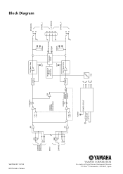
Box 3, Hamamatsu, 430-8651, Japan V617350 R1 1 IP 20 NP Printed in Taiwan CHANNEL L (BRIDGE) (PARALLEL) INPUT CHANNEL R BA CHANNEL L ATT • ON • OFF INV YAMAHA SPEAKER PROCESSING BA CHANNEL ATT R PARALLEL BRIDGE • ON • OFF STEREO POWER POWER CIRCUIT POWER SW Limiter Lch Power Amp CLIP Temperature Sensor (Heat Sink) Protection Circuit CLIP SIGNAL PROTECTION TEMP SIGNAL Limiter Rch Power Amp +B E -B +24 E -24 FAN SPEAKERS CHANNEL L L+R BRIDGE CHANNEL R Block Diagram YAMAHA CORPORATION Pro Audio & Digital Musical Instrument Division P.O.
Box 3, Hamamatsu, 430-8651, Japan V617350 R1 1 IP 20 NP Printed in Taiwan CHANNEL L (BRIDGE) (PARALLEL) INPUT CHANNEL R BA CHANNEL L ATT • ON • OFF INV YAMAHA SPEAKER PROCESSING BA CHANNEL ATT R PARALLEL BRIDGE • ON • OFF STEREO POWER POWER CIRCUIT POWER SW Limiter Lch Power Amp CLIP Temperature Sensor (Heat Sink) Protection Circuit CLIP SIGNAL PROTECTION TEMP SIGNAL Limiter Rch Power Amp +B E -B +24 E -24 FAN SPEAKERS CHANNEL L L+R BRIDGE CHANNEL R Block Diagram YAMAHA CORPORATION Pro Audio & Digital Musical Instrument Division P.O.

