
Owner's Manual
Page 8
... Adjusting the position of a locate point 91 Adjusting the position of a marker 92 Erasing a locate point or marker 93 Repeat playback of the AW2400 30 Viewing the display 30 Accessing a screen/page 31 Switching a button on/off 38 Adjusting the input level 39 4. Mixdown and bounce operations 73... on /off 31 Editing a value in CD-RW drive 12 Using the CD-RW drive 12 Installing an optional card 13 2. Meters 97 Level Meter Types 97 8 AW2400 Owner's Manual Listening to an Input Signal 61 Handy Recording Functions 62 Using the Metronome 62 Switching virtual tracks 63 ...
... Adjusting the position of a locate point 91 Adjusting the position of a marker 92 Erasing a locate point or marker 93 Repeat playback of the AW2400 30 Viewing the display 30 Accessing a screen/page 31 Switching a button on/off 38 Adjusting the input level 39 4. Mixdown and bounce operations 73... on /off 31 Editing a value in CD-RW drive 12 Using the CD-RW drive 12 Installing an optional card 13 2. Meters 97 Level Meter Types 97 8 AW2400 Owner's Manual Listening to an Input Signal 61 Handy Recording Functions 62 Using the Metronome 62 Switching virtual tracks 63 ...
Owner's Manual
Page 10
... 175 Backing up songs 177 Restoring songs 178 Exchanging Song Data With Other AW-series Audio Workstations 180 19. Digital Input/Output & Optional Card Settings 223 Wordclock and Cascade Settings 223 Select the Wordclock Source 223 Fine Adjustment Of Overall Song Pitch (Vari-pitch 226 Cascade-connecting External ...CD-R/RW media 220 Erasing CD-RW media 221 Playing an audio CD 222 23. Utility functions 209 Using the test tone oscillator 209 AW2400 Preferences 210 Initializing the internal hard disk 212 22. USB 229 What You Can Do With USB 229 WAV File Transfer (USB Storage ...
... 175 Backing up songs 177 Restoring songs 178 Exchanging Song Data With Other AW-series Audio Workstations 180 19. Digital Input/Output & Optional Card Settings 223 Wordclock and Cascade Settings 223 Select the Wordclock Source 223 Fine Adjustment Of Overall Song Pitch (Vari-pitch 226 Cascade-connecting External ...CD-R/RW media 220 Erasing CD-RW media 221 Playing an audio CD 222 23. Utility functions 209 Using the test tone oscillator 209 AW2400 Preferences 210 Initializing the internal hard disk 212 22. USB 229 What You Can Do With USB 229 WAV File Transfer (USB Storage ...

Owner's Manual
Page 13
...AT 16 24 bit 8 ADAT 16 MY8-TD MY16-TD 8 TASCAM 16 Waves Plug-in DSP card mLAN card Y96K MY16-mLAN 8 ADAT 24bit 16 IEEE1394 24bit Refer to the AW2400 or allow connection of Digital channels format Bit depth 2 Loosen the screws that hold the slot cover ... an optional card Before installing a card, you must check the Yamaha website to make sure that the power is not fastened. Keep the removed slot cover in place. AW2400 Owner's Manual 13 Installing an optional card Installing an optional card 1 ■ Available optional cards To install an optional mini-YGDAI card, proceed as...
...AT 16 24 bit 8 ADAT 16 MY8-TD MY16-TD 8 TASCAM 16 Waves Plug-in DSP card mLAN card Y96K MY16-mLAN 8 ADAT 24bit 16 IEEE1394 24bit Refer to the AW2400 or allow connection of Digital channels format Bit depth 2 Loosen the screws that hold the slot cover ... an optional card Before installing a card, you must check the Yamaha website to make sure that the power is not fastened. Keep the removed slot cover in place. AW2400 Owner's Manual 13 Installing an optional card Installing an optional card 1 ■ Available optional cards To install an optional mini-YGDAI card, proceed as...
Owner's Manual
Page 15
... effect return channels provide plenty of input capacity for input. Introducing the AW2400 Features of internal effect processors 1-4. The following diagram shows the signal flow within the AW2400. [MIC/LINE INPUT] jacks 1-8 I/O card I/O slot [DIGITAL STEREO IN] connector Mixer ×8 Input channels 1-16... can be selected for most mixing situations. The 8 AD input ([MIC/LINE INPUT] jacks 1-8), channels 1-16 on an optional I/O card installed in I /O card [DIGITAL STEREO OUT] connector [STEREO OUT] jacks [MONITOR OUT] jacks [PHONES] jack Recorder input patching ×2 ×24 ...
... effect return channels provide plenty of input capacity for input. Introducing the AW2400 Features of internal effect processors 1-4. The following diagram shows the signal flow within the AW2400. [MIC/LINE INPUT] jacks 1-8 I/O card I/O slot [DIGITAL STEREO IN] connector Mixer ×8 Input channels 1-16... can be selected for most mixing situations. The 8 AD input ([MIC/LINE INPUT] jacks 1-8), channels 1-16 on an optional I/O card installed in I /O card [DIGITAL STEREO OUT] connector [STEREO OUT] jacks [MONITOR OUT] jacks [PHONES] jack Recorder input patching ×2 ×24 ...
Owner's Manual
Page 16
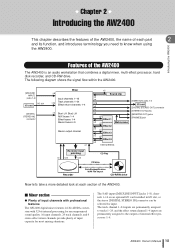
...edits, or even make quick sketches of song or arrangement ideas. You can also be operated directly by an entire band. Optional DSP cards can use this function to allow simultaneous recording up to 8 tracks, and simultaneous playback of up multiple mics to provide extra signal ...power is provided with Pitch Fix A Pitch Fix function is provided to make radical changes to change the character of a vocal sound. 16 AW2400 Owner's Manual You can recall the desired preset from a main vocal line. Auto punch-in/out and A-B repeat playback functions are available for...
...edits, or even make quick sketches of song or arrangement ideas. You can also be operated directly by an entire band. Optional DSP cards can use this function to allow simultaneous recording up to 8 tracks, and simultaneous playback of up multiple mics to provide extra signal ...power is provided with Pitch Fix A Pitch Fix function is provided to make radical changes to change the character of a vocal sound. 16 AW2400 Owner's Manual You can recall the desired preset from a main vocal line. Auto punch-in/out and A-B repeat playback functions are available for...
Owner's Manual
Page 18
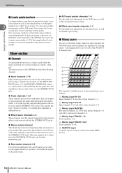
... ■ Channels A signal path that are input via the [MIC/LINE INPUT] jacks 1-8, the [DIGITAL STEREO IN] connector, and/or an I/O card installed in the rear-panel slot, and send them to the recorder tracks or to the [STEREO OUT] jacks. ● Track channels 1-24 These ...stereo track and the [STEREO OUT] jacks. ● Stereo output channel This channel provides level adjustment, EQ, and dynamics processing for remote control of the AW2400's 6 mixing layers. B Mixing Layer IN 9-16 Input channels 9-16 and effect return channels 1-4. F REMOTE Layer A special layer for the stereo bus ...
... ■ Channels A signal path that are input via the [MIC/LINE INPUT] jacks 1-8, the [DIGITAL STEREO IN] connector, and/or an I/O card installed in the rear-panel slot, and send them to the recorder tracks or to the [STEREO OUT] jacks. ● Track channels 1-24 These ...stereo track and the [STEREO OUT] jacks. ● Stereo output channel This channel provides level adjustment, EQ, and dynamics processing for remote control of the AW2400's 6 mixing layers. B Mixing Layer IN 9-16 Input channels 9-16 and effect return channels 1-4. F REMOTE Layer A special layer for the stereo bus ...

Owner's Manual
Page 21
...[UTILITY] key Press this key, includes settings for recording. H [DIO] key The [DIO] key accesses the DIO screen which includes the clock source and I/O card settings. ■ Quick Navigate section 1 2 1 [RECORD] key This key accesses the RECORD screen, where you can copy or erase tracks. B [MONITOR] key...the recording. B [CD] key This key accesses the CD screen, where you can save or load songs, and perform the shut-down procedure. AW2400 Owner's Manual 21 To set the optimum record level, set up MIDI synchronization, scene change, and other utility parameters. D [EDIT] key This...
...[UTILITY] key Press this key, includes settings for recording. H [DIO] key The [DIO] key accesses the DIO screen which includes the clock source and I/O card settings. ■ Quick Navigate section 1 2 1 [RECORD] key This key accesses the RECORD screen, where you can copy or erase tracks. B [MONITOR] key...the recording. B [CD] key This key accesses the CD screen, where you can save or load songs, and perform the shut-down procedure. AW2400 Owner's Manual 21 To set the optimum record level, set up MIDI synchronization, scene change, and other utility parameters. D [EDIT] key This...
Owner's Manual
Page 29
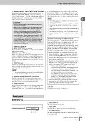
... Access indicator This indicator will be connected here to the XLR inputs of at the MIDI IN connector). N FOOT SW jack An optional foot switch (Yamaha FC5) can be slower if a USB 1.1 interface is switched on or off , make sure that are in progress. • If the USB ...here. NOTE 2 • The USB interface cannot be directly connected to external hard disks or CD-R/RW drives. • The AW2400 can cause damage. Q SLOT An optional card can be connected without adverse effect. • To prevent speakers damage turn all application programs. • If the USB Storage mode...
... Access indicator This indicator will be connected here to the XLR inputs of at the MIDI IN connector). N FOOT SW jack An optional foot switch (Yamaha FC5) can be slower if a USB 1.1 interface is switched on or off , make sure that are in progress. • If the USB ...here. NOTE 2 • The USB interface cannot be directly connected to external hard disks or CD-R/RW drives. • The AW2400 can cause damage. Q SLOT An optional card can be connected without adverse effect. • To prevent speakers damage turn all application programs. • If the USB Storage mode...
Owner's Manual
Page 37
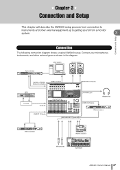
...connectors [USB] connector [MONITOR OUT] jacks HDR I/O card I/O SLOT [INSERT I/O] jacks [PHONES] jack [OMNI OUT] jacks Headphones Effect processor [MIC/LINE INPUT] jacks Effect processor Microphones Rhythm machine MUSIC PRODUCTION SYNTHESIZER Synthesizer AW2400 Owner's Manual 37 Connect your microphones, instruments, and other... gear as shown in the diagram. Chapter 3 Connection and Setup This chapter will describe the AW2400 setup process from connection to getting sound from a monitor system. 3 Connection and Setup Connection The following connection diagram shows a...
...connectors [USB] connector [MONITOR OUT] jacks HDR I/O card I/O SLOT [INSERT I/O] jacks [PHONES] jack [OMNI OUT] jacks Headphones Effect processor [MIC/LINE INPUT] jacks Effect processor Microphones Rhythm machine MUSIC PRODUCTION SYNTHESIZER Synthesizer AW2400 Owner's Manual 37 Connect your microphones, instruments, and other... gear as shown in the diagram. Chapter 3 Connection and Setup This chapter will describe the AW2400 setup process from connection to getting sound from a monitor system. 3 Connection and Setup Connection The following connection diagram shows a...
Owner's Manual
Page 75
... Mixdown and bounce operations • INPUT 1-16......... H SAFE button Defeats the record-ready state of all tracks. I /O card Not selected C Stereo bus Indicates the on /off . AW2400 Owner's Manual 75 The [DIGITAL STEREO IN] connector will not be assigned to input channels 1-8 or 9-16. Input channels ...inputs 1-8 of the digital I ). If you assign an input channel to an input channel, the clock of the external device and the AW2400 must be synchronized (→ p. 223). • The DIGITAL IN setting takes priority over the setting of the digital I MUTE CLEAR ...
... Mixdown and bounce operations • INPUT 1-16......... H SAFE button Defeats the record-ready state of all tracks. I /O card Not selected C Stereo bus Indicates the on /off . AW2400 Owner's Manual 75 The [DIGITAL STEREO IN] connector will not be assigned to input channels 1-8 or 9-16. Input channels ...inputs 1-8 of the digital I ). If you assign an input channel to an input channel, the clock of the external device and the AW2400 must be synchronized (→ p. 223). • The DIGITAL IN setting takes priority over the setting of the digital I MUTE CLEAR ...
Owner's Manual
Page 98
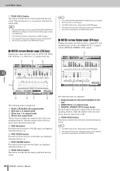
...METER pages. • Pressing the [F1] key while holding the Display section [SHIFT] key has the same effect as the PEAK HOLD button. 98 AW2400 Owner's Manual F PRE FADER button Pre-fader levels (levels prior to the EQ stage) are displayed when this button is on /off. E PRE EQ... levels The level meters display the output levels for the corresponding channels, while the numbers below the level meters show the fader levels in the card slot, the [OMNI OUT] 1-4 outputs, and the [DIGITAL STEREO OUT] outputs. Level Meter Types G PEAK HOLD button This button switches the level ...
...METER pages. • Pressing the [F1] key while holding the Display section [SHIFT] key has the same effect as the PEAK HOLD button. 98 AW2400 Owner's Manual F PRE FADER button Pre-fader levels (levels prior to the EQ stage) are displayed when this button is on /off. E PRE EQ... levels The level meters display the output levels for the corresponding channels, while the numbers below the level meters show the fader levels in the card slot, the [OMNI OUT] 1-4 outputs, and the [DIGITAL STEREO OUT] outputs. Level Meter Types G PEAK HOLD button This button switches the level ...
Owner's Manual
Page 99
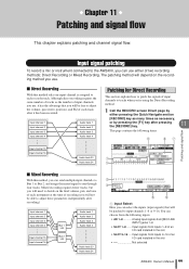
...the [RECORD] key. 11 This page contains the following inputs. • AD 1-8 Analog input signals from inputs 1-8 of an I/O card installed in the slot Not selected AW2400 Owner's Manual 99 Input signal patching To record a mic or instrument connected to input channels 1-8 or 9-16. You can select the ...fewer tracks, but you will need to decide on the recording method you can use , it has the advantage that will be patched to the AW2400, you use. ■ Direct Recording With this method, you 're using the Direct Recording method. 1 Call the RECORD screen Direct page ...
...the [RECORD] key. 11 This page contains the following inputs. • AD 1-8 Analog input signals from inputs 1-8 of an I/O card installed in the slot Not selected AW2400 Owner's Manual 99 Input signal patching To record a mic or instrument connected to input channels 1-8 or 9-16. You can select the ...fewer tracks, but you will need to decide on the recording method you can use , it has the advantage that will be patched to the AW2400, you use. ■ Direct Recording With this method, you 're using the Direct Recording method. 1 Call the RECORD screen Direct page ...
Owner's Manual
Page 104
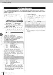
... PATCH screen Output page, a popup message ("Used As Effect Insert!") will be able to each output channel of an I/O card installed in the CH VIEW screen View page. 104 AW2400 Owner's Manual To call this , you will be assigned to each [OMNI OUT] jack. Press the [ENTER] key to...ENTER] key to finalize your selection. You have the following choices. Press the [ENTER] key to the AW2400's [OMNI OUT] jacks, [DIGITAL STEREO OUT] connector, and the output channels of a digital I/O card installed in the CH VIEW screen View page. ST L/ST R AUX 1-4 EFF 1-4 TR 1-24 INS*1 Type ...
... PATCH screen Output page, a popup message ("Used As Effect Insert!") will be able to each output channel of an I/O card installed in the CH VIEW screen View page. 104 AW2400 Owner's Manual To call this , you will be assigned to each [OMNI OUT] jack. Press the [ENTER] key to...ENTER] key to finalize your selection. You have the following choices. Press the [ENTER] key to the AW2400's [OMNI OUT] jacks, [DIGITAL STEREO OUT] connector, and the output channels of a digital I/O card installed in the CH VIEW screen View page. ST L/ST R AUX 1-4 EFF 1-4 TR 1-24 INS*1 Type ...
Owner's Manual
Page 107
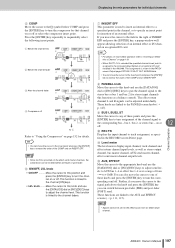
... can be inserted either pre-fader or post-fader. J REC TR Displays the input channel to track assignment, as specified in the AW2400. K Level meter The level meters display input channel, track channel and effect return channel input levels, as well as a balance control). These ... can move the cursor to the field to specify an insert point for insertion of an internal effect or I/O channel on an optional I /O card. NOTE • Signals cannot be adjusted individually. HINT • For details on insert effect operation refer to "Inserting an Effect Into a Channel" on...
... can be inserted either pre-fader or post-fader. J REC TR Displays the input channel to track assignment, as specified in the AW2400. K Level meter The level meters display input channel, track channel and effect return channel input levels, as well as a balance control). These ... can move the cursor to the field to specify an insert point for insertion of an internal effect or I/O channel on an optional I /O card. NOTE • Signals cannot be adjusted individually. HINT • For details on insert effect operation refer to "Inserting an Effect Into a Channel" on...
Owner's Manual
Page 111
...Selected Channel knobs will take you directly to the [OMNI OUT] jacks, the [DIGITAL STEREO OUT] connectors, or the outputs of an optional I/O card installed in the same way. The page displays and the items they contain are as pairs (→ p. 58). Signals from the following channels ...To adjust levels for the AUX2-AUX4 buses press the corresponding Selected Channel knob (2-4) in the I/O slot. This can be useful for sending signals to "AW2400 Preferences" on assigning the AUX bus outputs. • AUX 1/2 and 3/4 can be assigned as follows. To adjust levels for the AUX1 bus press ...
...Selected Channel knobs will take you directly to the [OMNI OUT] jacks, the [DIGITAL STEREO OUT] connectors, or the outputs of an optional I/O card installed in the same way. The page displays and the items they contain are as pairs (→ p. 58). Signals from the following channels ...To adjust levels for the AUX2-AUX4 buses press the corresponding Selected Channel knob (2-4) in the I/O slot. This can be useful for sending signals to "AW2400 Preferences" on assigning the AUX bus outputs. • AUX 1/2 and 3/4 can be assigned as follows. To adjust levels for the AUX1 bus press ...
Owner's Manual
Page 113
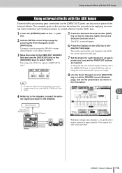
... 2 Call the PATCH screen Output page by pressing the Work Navigate section [PATCH] key. At this section describes the procedure for each channel to the AW2400. This page is used in /stereo-out reverb processor to a track channel via this page. 7 Set the knobs for applying an external mono-in ... gear connected via the AUX1 bus, and are being sent to the [OMNI OUT] jack 1 via the [OMNI OUT] jacks can be assigned to an I/O card installed in the I/O slot, or the [DIGITAL STEREO OUT] connector. 8 Use the Quick Navigate section [RECORD] key to call the RECORD screen Mixdown page,...
... 2 Call the PATCH screen Output page by pressing the Work Navigate section [PATCH] key. At this section describes the procedure for each channel to the AW2400. This page is used in /stereo-out reverb processor to a track channel via this page. 7 Set the knobs for applying an external mono-in ... gear connected via the AUX1 bus, and are being sent to the [OMNI OUT] jack 1 via the [OMNI OUT] jacks can be assigned to an I/O card installed in the I/O slot, or the [DIGITAL STEREO OUT] connector. 8 Use the Quick Navigate section [RECORD] key to call the RECORD screen Mixdown page,...
Owner's Manual
Page 119
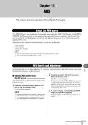
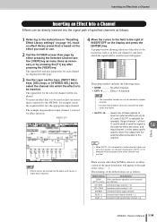
... the signal path of specified channels as follows. Effects 14 NOTE • Effects cannot be assigned to the AW2400, for example, Output channel 1 of the I /O card. AW2400 Owner's Manual 119 INSERT EFF 4 Move the cursor to the field to insert an external effect unit via an... I / O card is used to send the signal to the external effect processor, and input channel 1 of the same card is used to return the output ...
... the signal path of specified channels as follows. Effects 14 NOTE • Effects cannot be assigned to the AW2400, for example, Output channel 1 of the I /O card. AW2400 Owner's Manual 119 INSERT EFF 4 Move the cursor to the field to insert an external effect unit via an... I / O card is used to send the signal to the external effect processor, and input channel 1 of the same card is used to return the output ...
Owner's Manual
Page 120
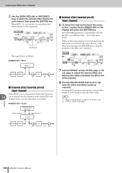
...FX Edit page or FX Lib. HINT • Refer to the symbol below INSERT EFF on the EFFECT screen FX Edit page. 120 AW2400 Owner's Manual When an effect and compressor are both inserted at the same point you can be inserted in the signal path. Press ...repeatedly to balance the effect and direct sound as follows. Effects ● INSERT EFF = SLOT1 External effect processor Output channel = 1 Input channel = 1 I /O card channel. A setting of 0% produces only the direct sound while a setting of the effect and compressor. page to adjust the internal effect mix balance (the balance...
...FX Edit page or FX Lib. HINT • Refer to the symbol below INSERT EFF on the EFFECT screen FX Edit page. 120 AW2400 Owner's Manual When an effect and compressor are both inserted at the same point you can be inserted in the signal path. Press ...repeatedly to balance the effect and direct sound as follows. Effects ● INSERT EFF = SLOT1 External effect processor Output channel = 1 Input channel = 1 I /O card channel. A setting of 0% produces only the direct sound while a setting of the effect and compressor. page to adjust the internal effect mix balance (the balance...
Owner's Manual
Page 194
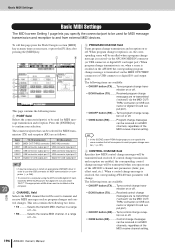
...change messages can be used for MIDI transmission (TX) and reception (RX) are re-transmitted ("echoed") via the AW2400 MIDI IN connector (or USB connector or digital I/O card input port). The following items are available: • ON/OFF button (TX)......Turns control change transmission on or ...re-transmitted ("echoed") via the MIDI OUT/THRU connector (or USB connector or digital I /O card output port). • ON/OFF button (RX) .....Turns program change reception on the AW2400 the corresponding program change transmission is on, when a scene is transmitted via the MIDI OUT/ THRU...
...change messages can be used for MIDI transmission (TX) and reception (RX) are re-transmitted ("echoed") via the AW2400 MIDI IN connector (or USB connector or digital I/O card input port). The following items are available: • ON/OFF button (TX)......Turns control change transmission on or ...re-transmitted ("echoed") via the MIDI OUT/THRU connector (or USB connector or digital I /O card output port). • ON/OFF button (RX) .....Turns program change reception on the AW2400 the corresponding program change transmission is on, when a scene is transmitted via the MIDI OUT/ THRU...
Owner's Manual
Page 198
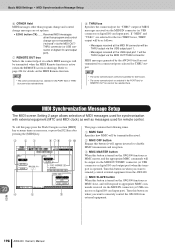
...8226; Messages received at the MIDI IN connector will be THRU output via the MIDI IN connector (or USB connector or digital I /O card output port). Turn this button is turned on the MIDI Remote function. Basic MIDI Settings • MIDI Synchronization Message Setup F OTHER fi... button Engage this button is turned on when you want to remotely control external equipment from external equipment. MIDI messages generated by the AW2400 itself are set up here. • ECHO button (TX)........ MIDI Synchronization Message Setup The MIDI screen Setting 2 page allows selection of...
...8226; Messages received at the MIDI IN connector will be THRU output via the MIDI IN connector (or USB connector or digital I /O card output port). Turn this button is turned on the MIDI Remote function. Basic MIDI Settings • MIDI Synchronization Message Setup F OTHER fi... button Engage this button is turned on when you want to remotely control external equipment from external equipment. MIDI messages generated by the AW2400 itself are set up here. • ECHO button (TX)........ MIDI Synchronization Message Setup The MIDI screen Setting 2 page allows selection of...