
Owner's Manual
Page 8
...45 6. Recording to back up your data 11 About the built-in CD-RW drive 12 Using the CD-RW drive 12 Installing an optional card 13 2. Mixdown and bounce operations 73 About mixdown and bouncing 73 Mixdown procedure 75 Playing back the stereo track 78 Bounce (ping-pong) ... 60 Applying Compression to the demo song 41 Loading the demo song 41 Playing the demo song 42 5. Meters 97 Level Meter Types 97 8 AW2400 Owner's Manual Track recording 47 Creating a new song 47 Direct recording and Mixed recording 49 Assigning input signals to tracks (Direct recording 51 Assigning...
...45 6. Recording to back up your data 11 About the built-in CD-RW drive 12 Using the CD-RW drive 12 Installing an optional card 13 2. Mixdown and bounce operations 73 About mixdown and bouncing 73 Mixdown procedure 75 Playing back the stereo track 78 Bounce (ping-pong) ... 60 Applying Compression to the demo song 41 Loading the demo song 41 Playing the demo song 42 5. Meters 97 Level Meter Types 97 8 AW2400 Owner's Manual Track recording 47 Creating a new song 47 Direct recording and Mixed recording 49 Assigning input signals to tracks (Direct recording 51 Assigning...
Owner's Manual
Page 10
...AW2400 mix operations on an external sequencer ....... 202 Using the MIDI Remote function 204 About the MIDI Remote function 204 Using the MIDI Remote function presets 204 Using User-defined Remote function 206 Remotely controlling a tone generator module .... 207 21. Digital Input/Output & Optional Card...Overall Song Pitch (Vari-pitch 226 Cascade-connecting External Devices 226 Check the Status Of the Digital Input Signal 227 Plug-in Card Settings 228 24. Automix 181 About Automix 181 Automix Operation 181 Creating a New Automix Recording 182 Recording the Automix Data ...
...AW2400 mix operations on an external sequencer ....... 202 Using the MIDI Remote function 204 About the MIDI Remote function 204 Using the MIDI Remote function presets 204 Using User-defined Remote function 206 Remotely controlling a tone generator module .... 207 21. Digital Input/Output & Optional Card...Overall Song Pitch (Vari-pitch 226 Cascade-connecting External Devices 226 Check the Status Of the Digital Input Signal 227 Plug-in Card Settings 228 24. Automix 181 About Automix 181 Automix Operation 181 Creating a New Automix Recording 182 Recording the Automix Data ...

Owner's Manual
Page 13
... a safe place. The following types of the card is not fastened. Push the card all the way into the slot. Installing an optional card Installing an optional card 1 ■ Available optional cards To install an optional mini-YGDAI card, proceed as Before you must check the Yamaha website to the AW2400 or allow connection of Digital channels format...
... a safe place. The following types of the card is not fastened. Push the card all the way into the slot. Installing an optional card Installing an optional card 1 ■ Available optional cards To install an optional mini-YGDAI card, proceed as Before you must check the Yamaha website to the AW2400 or allow connection of Digital channels format...
Owner's Manual
Page 15
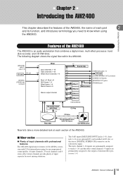
The following diagram shows the signal flow within the AW2400. [MIC/LINE INPUT] jacks 1-8 I/O card I/O slot [DIGITAL STEREO IN] connector Mixer ×8 Input channels 1-16 ×16 Track channels 1-24 Effect return channels 1-4 ×2 Bus1 L/R, Bus2 L/R AUX ... of the AW2400 The AW2400 is an audio workstation that combines a digital mixer, multi-effect processor, hard disk recorder, and CD-RW drive. The 8 AD input ([MIC/LINE INPUT] jacks 1-8), channels 1-16 on an optional I/O card installed in I /O card [DIGITAL STEREO OUT] connector [STEREO OUT] jacks [MONITOR OUT] jacks [...
The following diagram shows the signal flow within the AW2400. [MIC/LINE INPUT] jacks 1-8 I/O card I/O slot [DIGITAL STEREO IN] connector Mixer ×8 Input channels 1-16 ×16 Track channels 1-24 Effect return channels 1-4 ×2 Bus1 L/R, Bus2 L/R AUX ... of the AW2400 The AW2400 is an audio workstation that combines a digital mixer, multi-effect processor, hard disk recorder, and CD-RW drive. The 8 AD input ([MIC/LINE INPUT] jacks 1-8), channels 1-16 on an optional I/O card installed in I /O card [DIGITAL STEREO OUT] connector [STEREO OUT] jacks [MONITOR OUT] jacks [...
Owner's Manual
Page 16
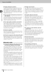
...; Totally redesigned operation The AW2400 is ideal for performance situations in which you compress or expand the time axis of the audio data over a range of 50%-200%. Optional DSP cards can individually be used to record a drum set to record multiple takes and select the best take ... a desired channel. ● Automix capability Full automix production power is also provided, letting you need to 12 tracks (→ p. 165). The AW2400 also has a metronome that follows the tempo map. ● Sound Clip function The Sound Clip function lets you can also be operated directly by ...
...; Totally redesigned operation The AW2400 is ideal for performance situations in which you compress or expand the time axis of the audio data over a range of 50%-200%. Optional DSP cards can individually be used to record a drum set to record multiple takes and select the best take ... a desired channel. ● Automix capability Full automix production power is also provided, letting you need to 12 tracks (→ p. 165). The AW2400 also has a metronome that follows the tempo map. ● Sound Clip function The Sound Clip function lets you can also be operated directly by ...
Owner's Manual
Page 18
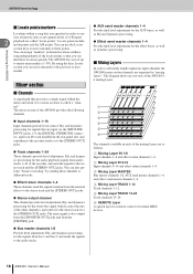
...Mixing Layer MASTER Bus master channels 1/2, AUX send master channels 1-4, and effect send master channels 1-4. The diagram shows an overview of the AW2400's 6 mixing layers. F REMOTE Layer A special layer for the stereo bus signal (which carries the mix of the other channels), ... points. AW2400 terminology Introducing the AW2400 ■ Locate points/markers Locations within a song that processes a single signal within a song independently of the locate points so that are input via the [MIC/LINE INPUT] jacks 1-8, the [DIGITAL STEREO IN] connector, and/or an I/O card installed in...
...Mixing Layer MASTER Bus master channels 1/2, AUX send master channels 1-4, and effect send master channels 1-4. The diagram shows an overview of the AW2400's 6 mixing layers. F REMOTE Layer A special layer for the stereo bus signal (which carries the mix of the other channels), ... points. AW2400 terminology Introducing the AW2400 ■ Locate points/markers Locations within a song that processes a single signal within a song independently of the locate points so that are input via the [MIC/LINE INPUT] jacks 1-8, the [DIGITAL STEREO IN] connector, and/or an I/O card installed in...

Owner's Manual
Page 21
... for fader grouping, the solo function, and more. H [DIO] key The [DIO] key accesses the DIO screen which includes the clock source and I/O card settings. ■ Quick Navigate section 1 2 1 [RECORD] key This key accesses the RECORD screen, where you can check whether each track, and make ...MIC/LINE INPUT jacks 1-8 to access the UTILITY screen with settings for the unit's test tone oscillator, digital inputs and outputs, and other settings. AW2400 Owner's Manual 21 E [MIDI] key Accesses the MIDI screen where you can copy or erase tracks. G [PATCH] key Accesses the PATCH ...
... for fader grouping, the solo function, and more. H [DIO] key The [DIO] key accesses the DIO screen which includes the clock source and I/O card settings. ■ Quick Navigate section 1 2 1 [RECORD] key This key accesses the RECORD screen, where you can check whether each track, and make ...MIC/LINE INPUT jacks 1-8 to access the UTILITY screen with settings for the unit's test tone oscillator, digital inputs and outputs, and other settings. AW2400 Owner's Manual 21 E [MIDI] key Accesses the MIDI screen where you can copy or erase tracks. G [PATCH] key Accesses the PATCH ...
Owner's Manual
Page 29
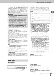
... groups 1 through 4 (CH1-4) and 5 through 8 (CH5-8). Q SLOT An optional card can be directly connected to be used . • When connecting via coaxial cable. N FOOT SW jack An optional foot switch (Yamaha FC5) can be properly installed to allow MIDI messages to a USB-equipped computer via the... the unit to be connected here to control transport operations such as a MIDI OUT (which transmits MIDI messages generated within the AW2400) or MIDI THRU (which retransmits messages that no equipment other than phantom-powered microphones is used for which phantom power is engaged...
... groups 1 through 4 (CH1-4) and 5 through 8 (CH5-8). Q SLOT An optional card can be directly connected to be used . • When connecting via coaxial cable. N FOOT SW jack An optional foot switch (Yamaha FC5) can be properly installed to allow MIDI messages to a USB-equipped computer via the... the unit to be connected here to control transport operations such as a MIDI OUT (which transmits MIDI messages generated within the AW2400) or MIDI THRU (which retransmits messages that no equipment other than phantom-powered microphones is used for which phantom power is engaged...
Owner's Manual
Page 37
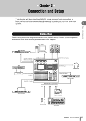
... to getting sound from a monitor system. 3 Connection and Setup Connection The following connection diagram shows a typical AW2400 setup. DAW system Monitor system Audio interface [DIGITAL STEREO IN/OUT] connectors [USB] connector [MONITOR OUT] jacks HDR I/O card I/O SLOT [INSERT I/O] jacks [PHONES] jack [OMNI OUT] jacks Headphones Effect processor [MIC/LINE INPUT] jacks Effect...
... to getting sound from a monitor system. 3 Connection and Setup Connection The following connection diagram shows a typical AW2400 setup. DAW system Monitor system Audio interface [DIGITAL STEREO IN/OUT] connectors [USB] connector [MONITOR OUT] jacks HDR I/O card I/O SLOT [INSERT I/O] jacks [PHONES] jack [OMNI OUT] jacks Headphones Effect processor [MIC/LINE INPUT] jacks Effect...
Owner's Manual
Page 75
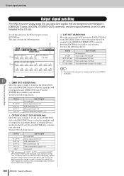
...signals from the AD inputs ([MIC/LINE INPUT] jacks 1-8) • SLOT1-8 The input signals from inputs 1-8 of the digital I /O card Not selected C Stereo bus Indicates the on /off status of the stereo track. The Mixdown page is the track channel number. If so,...muted consecutively starting with the last-numbered track. HINT • In order for the stereo output channel. You can perform mixdown operations. I ). AW2400 Owner's Manual 75 spond to the following items. • 1.2-15.16 ...... Input channels 1-16 • RETURN 1-4 ...... E LIBRARY button ...
...signals from the AD inputs ([MIC/LINE INPUT] jacks 1-8) • SLOT1-8 The input signals from inputs 1-8 of the digital I /O card Not selected C Stereo bus Indicates the on /off status of the stereo track. The Mixdown page is the track channel number. If so,...muted consecutively starting with the last-numbered track. HINT • In order for the stereo output channel. You can perform mixdown operations. I ). AW2400 Owner's Manual 75 spond to the following items. • 1.2-15.16 ...... Input channels 1-16 • RETURN 1-4 ...... E LIBRARY button ...
Owner's Manual
Page 98
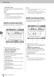
... levels The level meters display the output levels for the corresponding channels, while the numbers below the level meters show the fader levels in the card slot, the [OMNI OUT] 1-4 outputs, and the [DIGITAL STEREO OUT] outputs. When this button is on . G POST FADER button Post-fader levels...METER pages. • Pressing the [F1] key while holding the Display section [SHIFT] key has the same effect as the PEAK HOLD button. 98 AW2400 Owner's Manual HINT • The PEAK HOLD button setting affects all METER pages. • Pressing the [F1] key while holding the Display section [...
... levels The level meters display the output levels for the corresponding channels, while the numbers below the level meters show the fader levels in the card slot, the [OMNI OUT] 1-4 outputs, and the [DIGITAL STEREO OUT] outputs. When this button is on . G POST FADER button Post-fader levels...METER pages. • Pressing the [F1] key while holding the Display section [SHIFT] key has the same effect as the PEAK HOLD button. 98 AW2400 Owner's Manual HINT • The PEAK HOLD button setting affects all METER pages. • Pressing the [F1] key while holding the Display section [...
Owner's Manual
Page 99
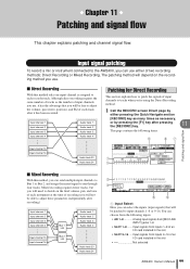
...8226; AD 1-8 Analog input signals from inputs 9-16 of each recorder track. Mixed recording requires fewer tracks, but you will be free to the AW2400, you can use . ■ Direct Recording With this method, you will depend on the final volume, pan, and tone of each instrument...Input signal patching To record a mic or instrument connected to adjust the volume, pan (stereo position), and EQ of an I /O card installed in the slot Not selected AW2400 Owner's Manual 99 You can send multiple input channels to Bus 1 or Bus 2, and assign the mixed signal to one input channel...
...8226; AD 1-8 Analog input signals from inputs 9-16 of each recorder track. Mixed recording requires fewer tracks, but you will be free to the AW2400, you can use . ■ Direct Recording With this method, you will depend on the final volume, pan, and tone of each instrument...Input signal patching To record a mic or instrument connected to adjust the volume, pan (stereo position), and EQ of an I /O card installed in the slot Not selected AW2400 Owner's Manual 99 You can send multiple input channels to Bus 1 or Bus 2, and assign the mixed signal to one input channel...
Owner's Manual
Page 104
.... You have to finalize your selection. Press the [ENTER] key to defeat the selection for INSERT EFF in the I /O card installed in the CH VIEW screen View page. 104 AW2400 Owner's Manual ST L/ST R AUX 1-4 EFF 1-4 TR 1-24 INS*1 Type of the stereo bus is selected for the corresponding output... channel in the I /O card installed in the CH VIEW screen View page. In order to change this, you will be assigned to...
.... You have to finalize your selection. Press the [ENTER] key to defeat the selection for INSERT EFF in the I /O card installed in the CH VIEW screen View page. 104 AW2400 Owner's Manual ST L/ST R AUX 1-4 EFF 1-4 TR 1-24 INS*1 Type of the stereo bus is selected for the corresponding output... channel in the I /O card installed in the CH VIEW screen View page. In order to change this, you will be assigned to...
Owner's Manual
Page 107
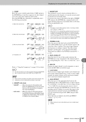
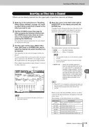
...pan the channel signal to adjust the channel level. G INSERT EFF This parameter is linked to reverse the order of an external effect. I /O card installed in the channel, or to the AUX and EFFECT screens (→ p. 111, 115). These functions are linked to sequentially select the following ...insert points. This function is used to insert an internal effect to a specified point in the AW2400. NOTE • Signals cannot be sent to the effect buses from - ∞ to +10dB. HINT • You can switch between pre-...
...pan the channel signal to adjust the channel level. G INSERT EFF This parameter is linked to reverse the order of an external effect. I /O card installed in the channel, or to the AUX and EFFECT screens (→ p. 111, 115). These functions are linked to sequentially select the following ...insert points. This function is used to insert an internal effect to a specified point in the AW2400. NOTE • Signals cannot be sent to the effect buses from - ∞ to +10dB. HINT • You can switch between pre-...
Owner's Manual
Page 111
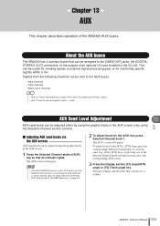
...the [DIGITAL STEREO OUT] connectors, or the outputs of the Selected Channel knobs (1-4) after pressing the [AUX] key so that its indicator lights. AW2400 Owner's Manual 111 The page displays and the items they contain are as pairs (→ p. 58). AUX Send Level Adjustment 13 AUX AUX ...Input/RTN page) or [F2] (Track page) key. NOTE • If the AUTO DISPLAY function is lit pressing one of an optional I/O card installed in the I/O slot. Chapter 13 AUX This chapter describes operation of the Selected Channel knobs will take you directly to external signal processing gear...
...the [DIGITAL STEREO OUT] connectors, or the outputs of the Selected Channel knobs (1-4) after pressing the [AUX] key so that its indicator lights. AW2400 Owner's Manual 111 The page displays and the items they contain are as pairs (→ p. 58). AUX Send Level Adjustment 13 AUX AUX ...Input/RTN page) or [F2] (Track page) key. NOTE • If the AUTO DISPLAY function is lit pressing one of an optional I/O card installed in the I/O slot. Chapter 13 AUX This chapter describes operation of the Selected Channel knobs will take you directly to external signal processing gear...
Owner's Manual
Page 113
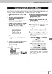
...to input channels 3/4 are mixed and sent to display the Track page. HINT • The AUX bus signals can also be assigned to an I/O card installed in the I/O slot, or the [DIGITAL STEREO OUT] connector. 8 Use the Quick Navigate section [RECORD] key to call the RECORD screen ...the knobs for applying an external mono-in the illustration. 13 AUX 4 Referring to the diagram, connect the external signal processor to the AW2400. AW2400 Owner's Manual 113 Using external effects with the AUX buses Using external effects with the AUX buses External effect processing gear connected via the ...
...to input channels 3/4 are mixed and sent to display the Track page. HINT • The AUX bus signals can also be assigned to an I/O card installed in the I/O slot, or the [DIGITAL STEREO OUT] connector. 8 Use the Quick Navigate section [RECORD] key to call the RECORD screen ...the knobs for applying an external mono-in the illustration. 13 AUX 4 Referring to the diagram, connect the external signal processor to the AW2400. AW2400 Owner's Manual 113 Using external effects with the AUX buses Using external effects with the AUX buses External effect processing gear connected via the ...
Owner's Manual
Page 119
... [SEL] keys, or [STEREO SEL] key to insert an external effect unit via an I / O card is used with the effect sends and returns. • SLOT1-16 ....... Select one instrument connected to the AW2400, for example, insert the required effect into which the signal will be sent/received will be inserted... preset that is to be directly inserted into the effect send master or effect return channels. A popup window allowing selection of the same card is used on the effect you want to the stereo channels and inserted. If SLOT1 is selected, for the selected channel will appear. ...
... [SEL] keys, or [STEREO SEL] key to insert an external effect unit via an I / O card is used with the effect sends and returns. • SLOT1-16 ....... Select one instrument connected to the AW2400, for example, insert the required effect into which the signal will be sent/received will be inserted... preset that is to be directly inserted into the effect send master or effect return channels. A popup window allowing selection of the same card is used on the effect you want to the stereo channels and inserted. If SLOT1 is selected, for the selected channel will appear. ...
Owner's Manual
Page 120
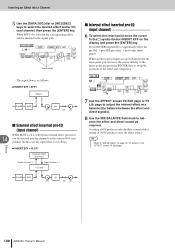
... can move the cursor to the symbol below INSERT EFF on the EFFECT screen FX Edit page. 120 AW2400 Owner's Manual Effects ● INSERT EFF = SLOT1 External effect processor Output channel = 1 Input channel = 1 I /O card channel, then press the [ENTER] key. HINT • Refer to "Editing Effects" on page 121 for... insert points. Inserting an Effect Into a Channel 5 Use the [DATA/JOG] dial or [INC]/[DEC] keys to select the desired effect and/or I /O card PHASE GATE EQ ATT ON LVL 7 Call the EFFECT screen FX Edit page or FX Lib. When an effect and compressor are both inserted at...
... can move the cursor to the symbol below INSERT EFF on the EFFECT screen FX Edit page. 120 AW2400 Owner's Manual Effects ● INSERT EFF = SLOT1 External effect processor Output channel = 1 Input channel = 1 I /O card channel, then press the [ENTER] key. HINT • Refer to "Editing Effects" on page 121 for... insert points. Inserting an Effect Into a Channel 5 Use the [DATA/JOG] dial or [INC]/[DEC] keys to select the desired effect and/or I /O card PHASE GATE EQ ATT ON LVL 7 Call the EFFECT screen FX Edit page or FX Lib. When an effect and compressor are both inserted at...
Owner's Manual
Page 194
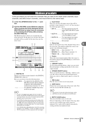
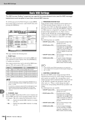
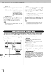
...USB connector output port 3 USB connector input port 3 Digital I/O card output port Digital I /O card input port). When a control change reception on all MIDI channels, regardless of the MIDI receive channel setting. 194 AW2400 Owner's Manual This area contains the following items are available: &#... C PROGRAM CHANGE field Turns program change transmission and reception are re-transmitted ("echoed") via the AW2400 MIDI IN connector (or USB connector or digital I /O card output port 20 MIDI NOTE • It may be transmitted and received. The following two items. &#...
...USB connector output port 3 USB connector input port 3 Digital I/O card output port Digital I /O card input port). When a control change reception on all MIDI channels, regardless of the MIDI receive channel setting. 194 AW2400 Owner's Manual This area contains the following items are available: &#... C PROGRAM CHANGE field Turns program change transmission and reception are re-transmitted ("echoed") via the AW2400 MIDI IN connector (or USB connector or digital I /O card output port 20 MIDI NOTE • It may be transmitted and received. The following two items. &#...
Owner's Manual
Page 198
...control change messages are re-transmitted ("echoed") via the MIDI OUT/ THRU connector (or USB connector or digital I/O card output port). MIDI messages generated by the AW2400 itself are selected for THRU output. B MMC OFF button Engage this button on when you want to disable MMC ... page allows selection of MIDI messages received via the MIDI OUT/THRU connector (or USB connector or digital I/O card output port) when the transport is turned on the AW2400 functions as messages used for synchronization with external equipment (MTC and MIDI clock) as well as MMC master,...
...control change messages are re-transmitted ("echoed") via the MIDI OUT/ THRU connector (or USB connector or digital I/O card output port). MIDI messages generated by the AW2400 itself are selected for THRU output. B MMC OFF button Engage this button on when you want to disable MMC ... page allows selection of MIDI messages received via the MIDI OUT/THRU connector (or USB connector or digital I/O card output port) when the transport is turned on the AW2400 functions as messages used for synchronization with external equipment (MTC and MIDI clock) as well as MMC master,...