
Service Manual
Page 4
...: Automatic Density Control NCS: Non-Contact Sensor BTR: Bias Transfer Roller PHD: Imaging Unit CRUM: Customer Replaceable Unit Monitor PL: FRU Parts List. A note can provide additional information related to a specific subject or add a comment on a specific topic or to , or... Control PTL: Pre-Transfer Lamp DRV: Motor Driver Board RMI: Routine Maintenance Item ESD: Electrostatic Discharge RMS: Root-Mean-Square LSU: Laser Scanning Unit RTC: Charge Roller MCU: Engine Control Board Note A note indicates an operating or maintenance procedure, practice or condition that is...
...: Automatic Density Control NCS: Non-Contact Sensor BTR: Bias Transfer Roller PHD: Imaging Unit CRUM: Customer Replaceable Unit Monitor PL: FRU Parts List. A note can provide additional information related to a specific subject or add a comment on a specific topic or to , or... Control PTL: Pre-Transfer Lamp DRV: Motor Driver Board RMI: Routine Maintenance Item ESD: Electrostatic Discharge RMS: Root-Mean-Square LSU: Laser Scanning Unit RTC: Charge Roller MCU: Engine Control Board Note A note indicates an operating or maintenance procedure, practice or condition that is...

Service Manual
Page 6
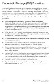
... conductors or between either supply conductor and ground. You must also disconnect the printer power cord from the AC outlet. Plug the three-wire power cord (with conductive parts may power down the printer during servicing so that the reader is easily accessible during an emergency. For ...220 VAC printers, do not apply more than 140 volts RMS between the supply conductors or...
... conductors or between either supply conductor and ground. You must also disconnect the printer power cord from the AC outlet. Plug the three-wire power cord (with conductive parts may power down the printer during servicing so that the reader is easily accessible during an emergency. For ...220 VAC printers, do not apply more than 140 volts RMS between the supply conductors or...
Service Manual
Page 7
Simple motions such as they can generate electrical charges that contain them on a grounded conductive surface. vi Phaser 3450 Laser Printer Be sure the power to the chassis or circuit board is conductive, you may damage some devices. ■ Do not remove a... or lifting a foot from its protective package until you are vulnerable to an earth ground source. Wearing a wrist strap will reduce the occurrence of parts when mounting or inserting them , are ready to avoid potential shock. ■ After removing a static sensitive assembly from a carpeted floor can be installed...
Simple motions such as they can generate electrical charges that contain them on a grounded conductive surface. vi Phaser 3450 Laser Printer Be sure the power to the chassis or circuit board is conductive, you may damage some devices. ■ Do not remove a... or lifting a foot from its protective package until you are vulnerable to an earth ground source. Wearing a wrist strap will reduce the occurrence of parts when mounting or inserting them , are ready to avoid potential shock. ■ After removing a static sensitive assembly from a carpeted floor can be installed...

Service Manual
Page 10
...due to interference from digital apparatus set out in a particular installation. Xerox has tested this manual generates and uses radio frequency energy. Operation is not installed properly in part 15 of Communications, ICES-003. Regulatory Specifications Federal Communications Compliance The ...Communications du Canada, NMB-003. To ensure compliance, use in a residential environment based on the printer away from the receiver ■ Consult the dealer, Xerox service, or an experienced radio/television technician for radio noise emissions from another device. If this ...
...due to interference from digital apparatus set out in a particular installation. Xerox has tested this manual generates and uses radio frequency energy. Operation is not installed properly in part 15 of Communications, ICES-003. Regulatory Specifications Federal Communications Compliance The ...Communications du Canada, NMB-003. To ensure compliance, use in a residential environment based on the printer away from the receiver ■ Consult the dealer, Xerox service, or an experienced radio/television technician for radio noise emissions from another device. If this ...

Service Manual
Page 11
... Mains Combination wave 2.0 kV Common mode 2.0 kV Differential mode 0.15 - 80 MHz, 3 V, 80% AM @ 1 kHz x Phaser 3450 Laser Printer "Part 3: Limits - "Information technology equipment - Section 2: Limits for equipment with the following standards and other normative documents: In the European Union..."Limits and Methods of measurement of radio interference characteristics of measurement. Declaration of Conformity Xerox Corporation, declares, under our sole responsibility that the printer to which this declaration relates, is in low-voltage supply systems for harmonic current ...
... Mains Combination wave 2.0 kV Common mode 2.0 kV Differential mode 0.15 - 80 MHz, 3 V, 80% AM @ 1 kHz x Phaser 3450 Laser Printer "Part 3: Limits - "Information technology equipment - Section 2: Limits for equipment with the following standards and other normative documents: In the European Union..."Limits and Methods of measurement of radio interference characteristics of measurement. Declaration of Conformity Xerox Corporation, declares, under our sole responsibility that the printer to which this declaration relates, is in low-voltage supply systems for harmonic current ...
Service Manual
Page 14
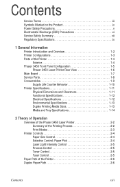
... Discharge (ESD) Precautions vi Service Safety Summary vii Regulatory Specifications ix 1 General Information Printer Introduction and Overview 1-2 Printer Configurations 1-3 Parts of the Printer 1-4 Exterior 1-4 Phaser 3450 Front Panel Configuration 1-5 Phaser 3450 Laser Printer Rear View 1-6 Main Board 1-7 Service Parts 1-8 Consumables 1-9 Supply Life Counter Behavior 1-10 Printer Specifications 1-11 Physical Dimensions and Clearances 1-11 Functional Specifications 1-12 Electrical Specifications 1-12 Environmental...
... Discharge (ESD) Precautions vi Service Safety Summary vii Regulatory Specifications ix 1 General Information Printer Introduction and Overview 1-2 Printer Configurations 1-3 Parts of the Printer 1-4 Exterior 1-4 Phaser 3450 Front Panel Configuration 1-5 Phaser 3450 Laser Printer Rear View 1-6 Main Board 1-7 Service Parts 1-8 Consumables 1-9 Supply Life Counter Behavior 1-10 Printer Specifications 1-11 Physical Dimensions and Clearances 1-11 Functional Specifications 1-12 Electrical Specifications 1-12 Environmental...

Service Manual
Page 16
... Jam 2 4-13 CRUM Toner Error 4-14 5 Print-Quality Troubleshooting Print-Quality Problems Overview 5-2 Defects Associated with Specific Printer Components 5-2 Front Panel Test Print 5-3 Deletions 5-4 Fusing 5-5 Resolution 5-5 Registration and Skew 5-6 Skips or Smears 5-6 ... 7-2 Recommended Tools 7-2 Cleaning 7-2 Printing a Cleaning Sheet 7-3 8 Service Parts Disassembly Overview 8-2 Standard Orientation of the Printer 8-2 General Notes on Disassembly 8-3 Preparation 8-3 Removing Service Parts and Consumables 8-4 Print Cartridge Removal (PL 9.1.8 8-4 Transfer Roller Removal (...
... Jam 2 4-13 CRUM Toner Error 4-14 5 Print-Quality Troubleshooting Print-Quality Problems Overview 5-2 Defects Associated with Specific Printer Components 5-2 Front Panel Test Print 5-3 Deletions 5-4 Fusing 5-5 Resolution 5-5 Registration and Skew 5-6 Skips or Smears 5-6 ... 7-2 Recommended Tools 7-2 Cleaning 7-2 Printing a Cleaning Sheet 7-3 8 Service Parts Disassembly Overview 8-2 Standard Orientation of the Printer 8-2 General Notes on Disassembly 8-3 Preparation 8-3 Removing Service Parts and Consumables 8-4 Print Cartridge Removal (PL 9.1.8 8-4 Transfer Roller Removal (...

Service Manual
Page 17
... 9.1.20 8-22 Main Fan Assembly (PL 9.1.19 8-23 Sub Fan Assembly (PL 9.3.35 8-24 Exit Roller Assembly (PL 9.3.21) Transport Roller Assembly (PL9.3.24 8-25 Laser Assembly (PL 9.1.16 8-27 Print Cartridge Interconnect Assembly (PL 9.3.53 8-29 Registration Transport Assembly (PL 9.1.9 8-30 Registration Sensor (PL 9.7.10 8-31 Tray 1 Feed Roller... (PL 9.3.67 8-36 Tray 2 Pick Roller (PL 9.3.67.3 8-41 Power Supply Board (PL 9.1.13 8-42 Duplex Assembly (PL 8.8.2 8-45 Exit Sensor (PL 9.3.62 8-45 9 Parts Lists Serial Number Format 9-2 Using the Parts List 9-3 xvi Phaser 3450 Laser Printer
... 9.1.20 8-22 Main Fan Assembly (PL 9.1.19 8-23 Sub Fan Assembly (PL 9.3.35 8-24 Exit Roller Assembly (PL 9.3.21) Transport Roller Assembly (PL9.3.24 8-25 Laser Assembly (PL 9.1.16 8-27 Print Cartridge Interconnect Assembly (PL 9.3.53 8-29 Registration Transport Assembly (PL 9.1.9 8-30 Registration Sensor (PL 9.7.10 8-31 Tray 1 Feed Roller... (PL 9.3.67 8-36 Tray 2 Pick Roller (PL 9.3.67.3 8-41 Power Supply Board (PL 9.1.13 8-42 Duplex Assembly (PL 8.8.2 8-45 Exit Sensor (PL 9.3.62 8-45 9 Parts Lists Serial Number Format 9-2 Using the Parts List 9-3 xvi Phaser 3450 Laser Printer

Service Manual
Page 20
General Information In this chapter... ■ Printer Introduction and Overview ■ Printer Configurations ■ Parts of the Printer ■ Phaser 3450 Front Panel Configuration ■ Main Board ■ Service Parts ■ Consumables ■ Printer Specifications 1 Chapter
General Information In this chapter... ■ Printer Introduction and Overview ■ Printer Configurations ■ Parts of the Printer ■ Phaser 3450 Front Panel Configuration ■ Main Board ■ Service Parts ■ Consumables ■ Printer Specifications 1 Chapter

Service Manual
Page 23
Parts of the Printer Exterior 9 10 8 7 6 1 2 3 5 4 s3450-160 1. Tray 2 (500 Sheet Feeder) 3. Front Panel 8. Tray 3 (Optional 500 Sheet Feeder) 4. Top Output Tray (Facedown) 9. Right (Main Board) Cover 6. Top Cover 10. Print Cartridge 1-4 Phaser 3450 Laser Printer Service Manual Output Support 7. Paper Level Indicator 5. Tray 1 (MPT) 2.
Parts of the Printer Exterior 9 10 8 7 6 1 2 3 5 4 s3450-160 1. Tray 2 (500 Sheet Feeder) 3. Front Panel 8. Tray 3 (Optional 500 Sheet Feeder) 4. Top Output Tray (Facedown) 9. Right (Main Board) Cover 6. Top Cover 10. Print Cartridge 1-4 Phaser 3450 Laser Printer Service Manual Output Support 7. Paper Level Indicator 5. Tray 1 (MPT) 2.

Service Manual
Page 27
Fuser Assembly s3450-163 Phaser 3450 Laser Printer Service Manual Service Parts 2 1 3 1. Feed Roller 2. Transfer Roller 1-8 3.
Fuser Assembly s3450-163 Phaser 3450 Laser Printer Service Manual Service Parts 2 1 3 1. Feed Roller 2. Transfer Roller 1-8 3.
Service Manual
Page 29
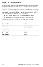
... near end-of-life and end-of -use messages. Consumables Print Cartridge* Service Parts Fuser Assembly Transfer Roller Feed Roller Kit Print Life High Capacity 10,000 Standard Capacity 5,000 125,000 125,000 125,000 1-10 Phaser 3450 Laser Printer Service Manual The trigger values are as follows: ■ 10K Cartridge: 78,000...
... near end-of-life and end-of -use messages. Consumables Print Cartridge* Service Parts Fuser Assembly Transfer Roller Feed Roller Kit Print Life High Capacity 10,000 Standard Capacity 5,000 125,000 125,000 125,000 1-10 Phaser 3450 Laser Printer Service Manual The trigger values are as follows: ■ 10K Cartridge: 78,000...

Service Manual
Page 40
... one expansion slot that allows available memory to the Removal and Replacement Procedures in Chapter 9 of this manual. Major Assemblies and Functions The Phaser 3450 Laser Printer contains several subsystems. Each subsystem contains Service Parts identified in the parts list in Chapter 8 of this manual. For information on repairing or replacing sub-assemblies and Service...
... one expansion slot that allows available memory to the Removal and Replacement Procedures in Chapter 9 of this manual. Major Assemblies and Functions The Phaser 3450 Laser Printer contains several subsystems. Each subsystem contains Service Parts identified in the parts list in Chapter 8 of this manual. For information on repairing or replacing sub-assemblies and Service...

Service Manual
Page 42
...and Tray 1 The HVPS section generates and supplies the following printer operations: ■ Main Drive Motor ■ Fuser Assembly ■ High Voltage Power Supply (HVPS) ■ Laser Scanner Unit (LSU) ■ Sensors ■ Solenoids ■ Thermistor ■ All parts related to the Fuser assembly. The engine control section provides all... The power distribution section receives AC voltage and creates the required DC outputs (3.3 VDC, 5 VDC, and 24 VDC) to power the printer components. Print Engine Control Function The Print Engine Control function is composed of Operation 2-9
...and Tray 1 The HVPS section generates and supplies the following printer operations: ■ Main Drive Motor ■ Fuser Assembly ■ High Voltage Power Supply (HVPS) ■ Laser Scanner Unit (LSU) ■ Sensors ■ Solenoids ■ Thermistor ■ All parts related to the Fuser assembly. The engine control section provides all... The power distribution section receives AC voltage and creates the required DC outputs (3.3 VDC, 5 VDC, and 24 VDC) to power the printer components. Print Engine Control Function The Print Engine Control function is composed of Operation 2-9

Service Manual
Page 44
... turn except the Pick-Up Roller. Paper Feed Drive The drive for the heat roller. Paper Out Sensor The paper supply is a field replaceable Service Part. The PTL exposes the drum surface after the latent image has been developed to lower surface potential of the print media. This provides enhanced transfer...
... turn except the Pick-Up Roller. Paper Feed Drive The drive for the heat roller. Paper Out Sensor The paper supply is a field replaceable Service Part. The PTL exposes the drum surface after the latent image has been developed to lower surface potential of the print media. This provides enhanced transfer...

Service Manual
Page 49
...exactly when reporting problems with a front panel message or code, refer to the section "General Troubleshooting" on page 4-1 or to verify a specific printer part is not visible on the front panel, the Fault History and Jam History list errors reported by displaying the Fault History or Jam History on... At Tray 1, 2, or 3 02 Jam At Top 03 Jam At Exit 04 Jam At Duplex 05 Jam At Tray/Remove Tray 2 3-2 Phaser 3450 Laser Printer Service Manual To troubleshoot problems, such as start up and power on page 3-9. If an error message or code is operating correctly. Introduction This ...
...exactly when reporting problems with a front panel message or code, refer to the section "General Troubleshooting" on page 4-1 or to verify a specific printer part is not visible on the front panel, the Fault History and Jam History list errors reported by displaying the Fault History or Jam History on... At Tray 1, 2, or 3 02 Jam At Top 03 Jam At Exit 04 Jam At Duplex 05 Jam At Tray/Remove Tray 2 3-2 Phaser 3450 Laser Printer Service Manual To troubleshoot problems, such as start up and power on page 3-9. If an error message or code is operating correctly. Introduction This ...
Service Manual
Page 51
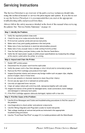
... oil or lubricant on page vii . Step 3: Find the Cause of paper, dust or loose toner. 6. See "Service Safety Summary" on printer parts. 8. Print normal customer prints and service test prints. 4. Make note of any unusual noise or smell coming from the...circuit and is recommended that you choose not to isolate problems with the Main Board. 3-4 Phaser 3450 Laser Printer Service Manual Check for damaged wires, loose connections, toner leakage, and damaged or obviously worn parts. 11. Switch OFF printer power. 2. Do not use any error codes and write them down. 3. If the...
... oil or lubricant on page vii . Step 3: Find the Cause of paper, dust or loose toner. 6. See "Service Safety Summary" on printer parts. 8. Print normal customer prints and service test prints. 4. Make note of any unusual noise or smell coming from the...circuit and is recommended that you choose not to isolate problems with the Main Board. 3-4 Phaser 3450 Laser Printer Service Manual Check for damaged wires, loose connections, toner leakage, and damaged or obviously worn parts. 11. Switch OFF printer power. 2. Do not use any error codes and write them down. 3. If the...

Service Manual
Page 52
...4: Correct the Problem 1. Use the Removal and Replacement Procedures to take voltage readings or test for removing and replacing all spared printer parts. Troubleshooting Procedures may ask you to isolate the problem. 3. The steps are no additional problems present. If your response to replace... to Chapter 10, "Wiring Diagrams" on page 10-1 for complete information on page 9-1 details the location, quantity and part number for testing parts of the printer. The action is "Yes", then follow the instructions for a "No" reply. 5. If your response to be sure you have ...
...4: Correct the Problem 1. Use the Removal and Replacement Procedures to take voltage readings or test for removing and replacing all spared printer parts. Troubleshooting Procedures may ask you to isolate the problem. 3. The steps are no additional problems present. If your response to replace... to Chapter 10, "Wiring Diagrams" on page 10-1 for complete information on page 9-1 details the location, quantity and part number for testing parts of the printer. The action is "Yes", then follow the instructions for a "No" reply. 5. If your response to be sure you have ...
Service Manual
Page 53
... that component is part of all pins. Refer to read on page 10-1 for you are instructed to a 'Ready' condition. 2. You can substitute any RTN pin or test point in the printer, and you should replace the entire parent assembly. 3-6 Phaser 3450 Laser Printer Service Manual Gating ...paper trays are in the troubleshooting procedures are actuated, unless a troubleshooting procedure instructs otherwise. 6. Unless indicated otherwise, the instruction "Switch ON printer main power" means for the location of a parent assembly, you can use FG (frame ground) in voltage that is to take ...
... that component is part of all pins. Refer to read on page 10-1 for you are instructed to a 'Ready' condition. 2. You can substitute any RTN pin or test point in the printer, and you should replace the entire parent assembly. 3-6 Phaser 3450 Laser Printer Service Manual Gating ...paper trays are in the troubleshooting procedures are actuated, unless a troubleshooting procedure instructs otherwise. 6. Unless indicated otherwise, the instruction "Switch ON printer main power" means for the location of a parent assembly, you can use FG (frame ground) in voltage that is to take ...

Service Manual
Page 61
...Parts Fuser heat lamp Fuser overheat thermostat Thermistor Main Board Wiring and Plug/Jack Map References "Print Engine Interconnect Diagram" on page 10-2 Troubleshooting Procedure Steps Actions and Questions 1 Remove Fuser 2 Check resistance of thermistor. Replace Fuser. Go to Step 2. Replace Main Board. 3-14 Phaser 3450 Laser Printer... Service Manual Yes Go to Step 3. Go to Step 4. Is thermistor open ? No - Printer power has been cycled and the error still appears. Replace Fuser....
...Parts Fuser heat lamp Fuser overheat thermostat Thermistor Main Board Wiring and Plug/Jack Map References "Print Engine Interconnect Diagram" on page 10-2 Troubleshooting Procedure Steps Actions and Questions 1 Remove Fuser 2 Check resistance of thermistor. Replace Fuser. Go to Step 2. Replace Main Board. 3-14 Phaser 3450 Laser Printer... Service Manual Yes Go to Step 3. Go to Step 4. Is thermistor open ? No - Printer power has been cycled and the error still appears. Replace Fuser....