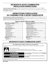
Installation Instructions
Page 1
... EXIGENCES D'INSTALLATION 13 Outillage et pièces 13 Ôter du gabarit de carton 14 Exigences d'emplacement 14 Dimensions du produit 14 Spécifications électriques 15 INSTRUCTIONS D'INSTALLATION 15 Dépose de la plaque de montage.../ Table des matières MICROWAVE HOOD COMBINATION SAFETY 1 INSTALLATION REQUIREMENTS 2 Tools and Parts 2 Remove Cardboard Template 2 Location Requirements 2 Product Dimensions 3 Electrical Requirements 3 INSTALLATION INSTRUCTIONS 4 Remove Mounting Plate 4 Rotate Blower Motor 4 Locate Wall Stud(s 6 Mark Rear Wall 7 Drill Holes ...
... EXIGENCES D'INSTALLATION 13 Outillage et pièces 13 Ôter du gabarit de carton 14 Exigences d'emplacement 14 Dimensions du produit 14 Spécifications électriques 15 INSTRUCTIONS D'INSTALLATION 15 Dépose de la plaque de montage.../ Table des matières MICROWAVE HOOD COMBINATION SAFETY 1 INSTALLATION REQUIREMENTS 2 Tools and Parts 2 Remove Cardboard Template 2 Location Requirements 2 Product Dimensions 3 Electrical Requirements 3 INSTALLATION INSTRUCTIONS 4 Remove Mounting Plate 4 Rotate Blower Motor 4 Locate Wall Stud(s 6 Mark Rear Wall 7 Drill Holes ...
Installation Instructions
Page 2
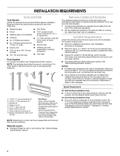
...of clearance between the wall and the microwave oven, so that the vent fits properly, and the damper blade opens freely and fully. See "Installation Dimensions" illustration. ■ Minimum one 2" x 4" (50.8 x 101.6 mm) wood wall stud and minimum 3/8" (9.5 mm) thickness drywall or ... Only: ■ If you are for cooking. Special Requirements For Wall Venting Installation Only: ■ Cutout must provide: ■ Minimum installation dimensions. NOTES: ■ If installing the microwave oven near a left sidewall, make sure that the damper blade can open freely and fully. NOTE:...
...of clearance between the wall and the microwave oven, so that the vent fits properly, and the damper blade opens freely and fully. See "Installation Dimensions" illustration. ■ Minimum one 2" x 4" (50.8 x 101.6 mm) wood wall stud and minimum 3/8" (9.5 mm) thickness drywall or ... Only: ■ If you are for cooking. Special Requirements For Wall Venting Installation Only: ■ Cutout must provide: ■ Minimum installation dimensions. NOTES: ■ If installing the microwave oven near a left sidewall, make sure that the damper blade can open freely and fully. NOTE:...
Installation Instructions
Page 3
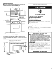
... current. Do not use an extension cord. Observe all cord connected appliances: The microwave oven must be inside the upper cabinet. Product Dimensions 17¹⁄₄" (43.8 cm) 16¹⁄₄" (41.3 cm) (401.05³c⁄₄m") 29⁷&#... ■ A time-delay fuse or time-delay circuit breaker. ■ A separate circuit serving only this microwave oven. WARNING: Improper use an extension cord. Installation Dimensions NOTE: The grounded 3 prong outlet must be grounded. Required: ■ A 120 Volt, 60 Hz, AC only, 15- A. 2" x 4" wall stud ...
... current. Do not use an extension cord. Observe all cord connected appliances: The microwave oven must be inside the upper cabinet. Product Dimensions 17¹⁄₄" (43.8 cm) 16¹⁄₄" (41.3 cm) (401.05³c⁄₄m") 29⁷&#... ■ A time-delay fuse or time-delay circuit breaker. ■ A separate circuit serving only this microwave oven. WARNING: Improper use an extension cord. Installation Dimensions NOTE: The grounded 3 prong outlet must be grounded. Required: ■ A 120 Volt, 60 Hz, AC only, 15- A. 2" x 4" wall stud ...
Installation Instructions
Page 7
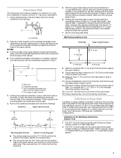
... corner of upper cabinet 3. A A. They must each other. Set the mounting plate aside. Using measuring tape, measure out 6" (15.2 cm) on a level line with the dimensions described in Step 4. Cut a 3/4" (19 mm) hole in one 1/4-20 x 3" round-head bolt with toggle nut; Using a keyhole saw, cut out the venting cutout area...
... corner of upper cabinet 3. A A. They must each other. Set the mounting plate aside. Using measuring tape, measure out 6" (15.2 cm) on a level line with the dimensions described in Step 4. Cut a 3/4" (19 mm) hole in one 1/4-20 x 3" round-head bolt with toggle nut; Using a keyhole saw, cut out the venting cutout area...
Installation Instructions
Page 8
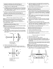
...(s)" section. Position mounting plate on the wall. 4. Insert lag screws into the wall stud at One End Hole (Figure 3) 1. Make sure the 10" (25.4 cm) dimension from upper cabinet. 3. Installation for Wall Stud at Both End Holes (Figure 4) 1. B A C A. 1/4-20 x 3" round-head bolt B. Check alignment of the microwave oven. If installing on...
...(s)" section. Position mounting plate on the wall. 4. Insert lag screws into the wall stud at One End Hole (Figure 3) 1. Make sure the 10" (25.4 cm) dimension from upper cabinet. 3. Installation for Wall Stud at Both End Holes (Figure 4) 1. B A C A. 1/4-20 x 3" round-head bolt B. Check alignment of the microwave oven. If installing on...

