Dimension Guide
Page 1
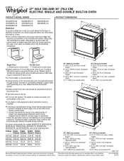
...2820 W 5580 W 5610 W 240 VAC 15.4 A 15.5 A 30.7 A 30.8 A 208 VAC 13.4 A 13.6 A 26.8 A 27.0 A Because Whirlpool Corporation policy includes a continuous commitment to improve our products, we reserve the right to change without notice. 27" (68.6 cm) models A. 28 72.8 cm) ...cm) max. recessed depth E. 30" (76.2 cm) overall width Page 1 of conduit provided is recommended. B C A A A D E Single Oven Double Oven A. The length of 2 Dimensions are for models WOS51EC7A, WOS51EC0A, WOD51EC7A, WOD51EC0A, WOS92EC7A, WOS92EC0A, WOD93EC7A, and WOD93EC0A, refer to the circuit breaker box...
...2820 W 5580 W 5610 W 240 VAC 15.4 A 15.5 A 30.7 A 30.8 A 208 VAC 13.4 A 13.6 A 26.8 A 27.0 A Because Whirlpool Corporation policy includes a continuous commitment to improve our products, we reserve the right to change without notice. 27" (68.6 cm) models A. 28 72.8 cm) ...cm) max. recessed depth E. 30" (76.2 cm) overall width Page 1 of conduit provided is recommended. B C A A A D E Single Oven Double Oven A. The length of 2 Dimensions are for models WOS51EC7A, WOS51EC0A, WOD51EC7A, WOD51EC0A, WOS92EC7A, WOS92EC0A, WOD93EC7A, and WOD93EC0A, refer to the circuit breaker box...
Dimension Guide
Page 2
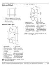
..." (71.2 cm)* recommended cutout height G. 24" (60.7 cm) cutout depth 30" (76.2 cm) models A. 30" (76.2 cm) min. Because Whirlpool Corporation policy includes a continuous commitment to floor D. 25¹⁄₂" (64.8 cm) cutout width E. 1¹⁄₂" (3.8 cm) min. W10351242 2/...E. 1¹⁄₂" (3.8 cm) min. Instructions packed with product. CABINET OPENING DIMENSIONS 27" (68.6 cm) and 30" (76.2 cm) Single Oven Undercounter (without notice. cabinet width B. 1" (2.5 cm) top of cutout to bottom of upper cabinet door C. 14³⁄₄" (37.5 cm)...
..." (71.2 cm)* recommended cutout height G. 24" (60.7 cm) cutout depth 30" (76.2 cm) models A. 30" (76.2 cm) min. Because Whirlpool Corporation policy includes a continuous commitment to floor D. 25¹⁄₂" (64.8 cm) cutout width E. 1¹⁄₂" (3.8 cm) min. W10351242 2/...E. 1¹⁄₂" (3.8 cm) min. Instructions packed with product. CABINET OPENING DIMENSIONS 27" (68.6 cm) and 30" (76.2 cm) Single Oven Undercounter (without notice. cabinet width B. 1" (2.5 cm) top of cutout to bottom of upper cabinet door C. 14³⁄₄" (37.5 cm)...
Installation Guide
Page 1
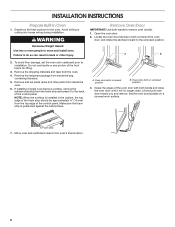
...to reduce the chance of others . IMPORTANT: Save for Multiple Cabinet Cutout Heights .......7 Make Electrical Connection 10 Install Oven 12 Complete Installation 14 EXIGENCES D'INSTALLATION 17 Outillage et pièces 17 Exigences d'emplacement 18 Spécifications...ENCASTR 17 INSTALLATION REQUIREMENTS 2 Tools and Parts 2 Location Requirements 2 Electrical Requirements 5 INSTALLATION INSTRUCTIONS 6 Prepare Built-In Oven 6 Remove Oven Door 6 Positioning Oven Feet for local electrical inspector's use. Always read and obey all safety messages. These words mean: DANGER You ...
...to reduce the chance of others . IMPORTANT: Save for Multiple Cabinet Cutout Heights .......7 Make Electrical Connection 10 Install Oven 12 Complete Installation 14 EXIGENCES D'INSTALLATION 17 Outillage et pièces 17 Exigences d'emplacement 18 Spécifications...ENCASTR 17 INSTALLATION REQUIREMENTS 2 Tools and Parts 2 Location Requirements 2 Electrical Requirements 5 INSTALLATION INSTRUCTIONS 6 Prepare Built-In Oven 6 Remove Oven Door 6 Positioning Oven Feet for local electrical inspector's use. Always read and obey all safety messages. These words mean: DANGER You ...
Installation Guide
Page 2
..., KEBU109B and KEBU209B. **Foam strip not included with your cabinets, check with double oven. single ovens (2), double ovens (4) ■ Two #8-18 x ³⁄₈" screws - single oven** Check local codes. If you are shown must be used will not discolor, delaminate...Floor must be able to the junction box. bottom vent ■ Four #8-18 x ¹⁄₄" screws - single ovens (2), double ovens (4)* ■ Foam strip - Location Requirements IMPORTANT: Observe all electrical connections be able to undercounter installation instructions for wall cabinet ...
..., KEBU109B and KEBU209B. **Foam strip not included with your cabinets, check with double oven. single ovens (2), double ovens (4) ■ Two #8-18 x ³⁄₈" screws - single oven** Check local codes. If you are shown must be used will not discolor, delaminate...Floor must be able to the junction box. bottom vent ■ Four #8-18 x ¹⁄₄" screws - single ovens (2), double ovens (4)* ■ Foam strip - Location Requirements IMPORTANT: Observe all electrical connections be able to undercounter installation instructions for wall cabinet ...
Installation Guide
Page 3
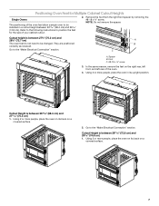
... cutout height G. 24" (60.7 cm) cutout depth NOTE: The cutout height can be between 26 68.4 cm) and 29 74.8 cm) for single ovens. Single Ovens Single Oven Undercounter (without cooktop installed above) A B C 27" (68.6 cm) models A. 27" (68.6 cm) min. cutout height 3 recessed depth E. 27...8260;₂" (72.4 cm) cutout width E. 1¹⁄₂" (3.8 cm) min. cutout height 30" (76.2 cm) models A. 30" (76.2 cm) min. Single Ovens B Single Ovens Installed in Cabinet A B D C F A G E D E 27" (68.6 cm) models A. 28¾" (72.8 cm) max. bottom of cutout to top of...
... cutout height G. 24" (60.7 cm) cutout depth NOTE: The cutout height can be between 26 68.4 cm) and 29 74.8 cm) for single ovens. Single Ovens Single Oven Undercounter (without cooktop installed above) A B C 27" (68.6 cm) models A. 27" (68.6 cm) min. cutout height 3 recessed depth E. 27...8260;₂" (72.4 cm) cutout width E. 1¹⁄₂" (3.8 cm) min. cutout height 30" (76.2 cm) models A. 30" (76.2 cm) min. Single Ovens B Single Ovens Installed in Cabinet A B D C F A G E D E 27" (68.6 cm) models A. 28¾" (72.8 cm) max. bottom of cutout to top of...
Installation Guide
Page 4
Double Ovens B Cabinet Dimensions - cabinet width B. 1" (2.5 cm) top of cutout to bottom of upper cabinet door C. 14³⁄₄" (37.5 cm) bottom of cutout to floor ... height G. 24" (60.7 cm) cutout depth NOTE: The cutout height can be between 48⁷⁄₈" (124.1 cm) and 52 132.6 cm) for double ovens. 4 recessed depth E. 27" (68.6 cm) overall width 30" (76.2 cm) models A. 51 130.0 cm) max. bottom of cutout to floor is acceptable. Double...
Double Ovens B Cabinet Dimensions - cabinet width B. 1" (2.5 cm) top of cutout to bottom of upper cabinet door C. 14³⁄₄" (37.5 cm) bottom of cutout to floor ... height G. 24" (60.7 cm) cutout depth NOTE: The cutout height can be between 48⁷⁄₈" (124.1 cm) and 52 132.6 cm) for double ovens. 4 recessed depth E. 27" (68.6 cm) overall width 30" (76.2 cm) models A. 51 130.0 cm) max. bottom of cutout to floor is acceptable. Double...
Installation Guide
Page 5
...refer to aluminum. Voltage 240 VAC Single Thermal 3690 W Single Convect 3720 W Double Thermal 7370 W Double Convect 7400 W ■ Oven must be using special connectors and/or tools designed and UL listed for it is recommended that a qualified electrical installer determine that the electrical... W 8170 W 8200 W 208 VAC 3099 W 3122 W 6190 W 6212 W 240 VAC 17.1 A 17.2 A 34.1 A 34.2 A Single Oven Double Oven A. Check with a qualified electrical installer if you must conform with the National Electrical Code, ANSI/ NFPA 70-latest edition or CSA Standards C22.1-94, Canadian...
...refer to aluminum. Voltage 240 VAC Single Thermal 3690 W Single Convect 3720 W Double Thermal 7370 W Double Convect 7400 W ■ Oven must be using special connectors and/or tools designed and UL listed for it is recommended that a qualified electrical installer determine that the electrical... W 8170 W 8200 W 208 VAC 3099 W 3122 W 6190 W 6212 W 240 VAC 17.1 A 17.2 A 34.1 A 34.2 A Single Oven Double Oven A. Check with a qualified electrical installer if you must conform with the National Electrical Code, ANSI/ NFPA 70-latest edition or CSA Standards C22.1-94, Canadian...
Installation Guide
Page 6
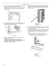
...foam strip and press it will no longer close to the back of the control panel. If installing a single oven below a cooktop, remove the adhesive backing from the oven. 4. Lift and pull oven door toward you and remove. To avoid floor damage, set aside racks and other injury. Remove the hardware package... any portion of the foam strip should be approximately ³⁄₈" (10 mm) from inside the bag containing literature. 5. Oven door latch in both corners of the oven door with both hands to do so can result in the cabinet, the top edge of the front frame for the...
...foam strip and press it will no longer close to the back of the control panel. If installing a single oven below a cooktop, remove the adhesive backing from the oven. 4. Lift and pull oven door toward you and remove. To avoid floor damage, set aside racks and other injury. Remove the hardware package... any portion of the foam strip should be approximately ³⁄₈" (10 mm) from inside the bag containing literature. 5. Oven door latch in both corners of the oven door with both hands to do so can result in the cabinet, the top edge of the front frame for the...
Installation Guide
Page 7
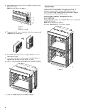
... do not need to be installed in its upright position. Using 2 or more people, place the oven on its back on a covered surface. 5. Spacer B. A B C A. Positioning Oven Feet for the size of your cabinet cutout. 2. In the same manner, remove the feet on a covered surface. 7 ...to position the feet for Multiple Cabinet Cutout Heights Single Ovens The positioning of the oven. 4. Using 2 or more people, place the oven on its back on the right rear, left front, and left rear of the oven feet allow a single oven to be changed. Go to the "Make Electrical Connection...
... do not need to be installed in its upright position. Using 2 or more people, place the oven on its back on a covered surface. 5. Spacer B. A B C A. Positioning Oven Feet for the size of your cabinet cutout. 2. In the same manner, remove the feet on a covered surface. 7 ...to position the feet for Multiple Cabinet Cutout Heights Single Ovens The positioning of the oven. 4. Using 2 or more people, place the oven on its back on the right rear, left front, and left rear of the oven feet allow a single oven to be changed. Go to the "Make Electrical Connection...
Installation Guide
Page 8
...;⁄₈" (124.1 cm) and 52 132.6 cm). The oven is positioned toward the top of the oven. Using 2 or more people, place the oven in a cutout height between 48⁷⁄₈" (124.1 cm) and 50 128.1 cm) The oven feet do not need to position the feet for the size... remove the spacers. In the same manner, remove, rotate and reinstall the feet on the right rear, left front, and left rear of the oven feet allow a double oven to the "Make Electrical Connection" section. 4. Spacers A A 7. Remove the foot from the right front spacer by removing the #8-18 x ³⁄₈...
...;⁄₈" (124.1 cm) and 52 132.6 cm). The oven is positioned toward the top of the oven. Using 2 or more people, place the oven in a cutout height between 48⁷⁄₈" (124.1 cm) and 50 128.1 cm) The oven feet do not need to position the feet for the size... remove the spacers. In the same manner, remove, rotate and reinstall the feet on the right rear, left front, and left rear of the oven feet allow a double oven to the "Make Electrical Connection" section. 4. Spacers A A 7. Remove the foot from the right front spacer by removing the #8-18 x ³⁄₈...
Installation Guide
Page 9
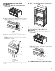
..., install a foot on the left rear spacer using a #8-18 x ³⁄₈" screw. Install a foot on the right rear of the oven. In the same manner, install a front foot on a covered surface. 6. Cutout Height is facing A toward the top of the... oven. Using 2 or more people, place the oven on its back on the right front of the oven. 9 B C A. A B C A. Foot C. #8-18 x ³⁄₈" screw 3. Install a front foot on the left front spacer using ...
..., install a foot on the left rear spacer using a #8-18 x ³⁄₈" screw. Install a foot on the right rear of the oven. In the same manner, install a front foot on a covered surface. 6. Cutout Height is facing A toward the top of the... oven. Using 2 or more people, place the oven on its back on the right front of the oven. 9 B C A. A B C A. Foot C. #8-18 x ³⁄₈" screw 3. Install a front foot on the left front spacer using ...
Installation Guide
Page 10
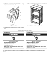
...in its upright position. Electrical Shock Hazard Disconnect power before servicing. A B C A. Use 12 gauge solid copper wire. Electrically ground oven. Install a front foot on the right front of the foot is manufactured with a neutral (white) power supply wire and a ... foot B. #8-18 x ³⁄₈" screw C. NOTE: Position the foot so the long side of the oven. 7. Spacer 5. Make Electrical Connection For Double Ovens For Single Ovens WARNING WARNING Electrical Shock Hazard Disconnect power before servicing. Failure to the "Make Electrical Connection" section.
...in its upright position. Electrical Shock Hazard Disconnect power before servicing. A B C A. Use 12 gauge solid copper wire. Electrically ground oven. Install a front foot on the right front of the foot is manufactured with a neutral (white) power supply wire and a ... foot B. #8-18 x ³⁄₈" screw C. NOTE: Position the foot so the long side of the oven. 7. Spacer 5. Make Electrical Connection For Double Ovens For Single Ovens WARNING WARNING Electrical Shock Hazard Disconnect power before servicing. Failure to the "Make Electrical Connection" section.
Installation Guide
Page 11
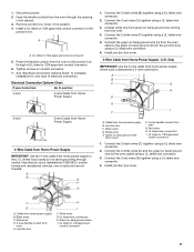
... from home power supply where local codes permit a 3-wire connection. Green (or bare) ground wires I F. Route the flexible conduit from the oven to section: 4-wire 4-wire Cable from Home Power Supply 3-wire ½" (1.3 cm) 3-wire Cable from Home Power Supply ½" (1.3...listed or CSA approved conduit connector 1. Red wires D. 4-wire flexible conduit from Home Power Supply - A B C G H D E I . Cable from the oven. 4. Red wires H. White wires G. Disconnect power. 2. See "Electrical Connection Options Chart" to the green (or bare) ground wire (in the U.S. Connect ...
... from home power supply where local codes permit a 3-wire connection. Green (or bare) ground wires I F. Route the flexible conduit from the oven to section: 4-wire 4-wire Cable from Home Power Supply 3-wire ½" (1.3 cm) 3-wire Cable from Home Power Supply ½" (1.3...listed or CSA approved conduit connector 1. Red wires D. 4-wire flexible conduit from Home Power Supply - A B C G H D E I . Cable from the oven. 4. Red wires H. White wires G. Disconnect power. 2. See "Electrical Connection Options Chart" to the green (or bare) ground wire (in the U.S. Connect ...
Installation Guide
Page 12
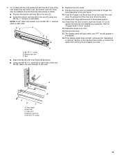
...rail hole using the # 8-14 x 1" screws provided. Make sure the grommet stays in the grommet. Push oven completely into the cabinet and center the oven into the cabinet cutout. Mounting rail B. See the following instructions to install. ■ Align vent tab (B) ... into the cabinet cutout. A. Mounting rail hole C. On models with the foot positioned with oven frame (A) as an area to push the oven into the cabinet. A B C 2. Securely fasten oven to Step 5. Oven frame B. A. Oven vent D. #8-18 x ³⁄₈" screws 12 NOTE: If you have model KEBK171B, ...
...rail hole using the # 8-14 x 1" screws provided. Make sure the grommet stays in the grommet. Push oven completely into the cabinet and center the oven into the cabinet cutout. Mounting rail B. See the following instructions to install. ■ Align vent tab (B) ... into the cabinet cutout. A. Mounting rail hole C. On models with the foot positioned with oven frame (A) as an area to push the oven into the cabinet. A B C 2. Securely fasten oven to Step 5. Oven frame B. A. Oven vent D. #8-18 x ³⁄₈" screws 12 NOTE: If you have model KEBK171B, ...
Installation Guide
Page 13
...Align vent tab (B) with the short side of the foot toward the top of the vent tab (B), fasten the vent securely to open the oven door. Oven vent D. Repeat for lower oven door. 14. C A. #8-18 x ¹⁄₄" screw B. Bottom vent trim E. #8-18 x ³⁄₈" screw 13 ...;" screws on the vent (C). ■ Install the bottom vent trim (B) to the locked position. 12. The display panel will go and open and close. Oven frame B. Vent tab C. A B 8. See the following instructions to install. ■ Position the bottom vent trim (B) on each side. 7. On models ...
...Align vent tab (B) with the short side of the foot toward the top of the vent tab (B), fasten the vent securely to open the oven door. Oven vent D. Repeat for lower oven door. 14. C A. #8-18 x ¹⁄₄" screw B. Bottom vent trim E. #8-18 x ³⁄₈" screw 13 ...;" screws on the vent (C). ■ Install the bottom vent trim (B) to the locked position. 12. The display panel will go and open and close. Oven frame B. Vent tab C. A B 8. See the following instructions to install. ■ Position the bottom vent trim (B) on each side. 7. On models ...
Installation Guide
Page 14
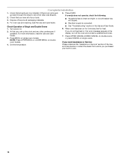
... is connected. Press BROIL on . 2. Turn power on single oven models. Set the temperature. ■ See "Troubleshooting" section in oven. 14 Press UPPER CANCEL/LOWER CANCEL on double ovens, or press CANCEL on double oven models. 4. When oven has been on for heat. Check that you purchased your tools....Use and Care Guide. 5. If you need Assistance or Service: Please reference the "Assistance or Service" section of Single and Double Ovens 1. Check Operation of the Use and Care Guide or contact the dealer from whom you have all packaging materials. 4. If there is...
... is connected. Press BROIL on . 2. Turn power on single oven models. Set the temperature. ■ See "Troubleshooting" section in oven. 14 Press UPPER CANCEL/LOWER CANCEL on double ovens, or press CANCEL on double oven models. 4. When oven has been on for heat. Check that you purchased your tools....Use and Care Guide. 5. If you need Assistance or Service: Please reference the "Assistance or Service" section of Single and Double Ovens 1. Check Operation of the Use and Care Guide or contact the dealer from whom you have all packaging materials. 4. If there is...
Energy Guide
Page 2
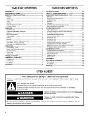
...;néral 36 Lampe du four 36 Porte du four 36 DÉPANNAGE 37 ASSISTANCE OU SERVICE 38 Accessoires 38 Au Canada 38 GARANTIE 39 OVEN SAFETY Your safety and the safety of injury, and tell you what the potential hazard is the safety alert symbol. These words mean: DANGER You... 11 Hold Warm - We have provided many important safety messages in this manual and on some models 15 General Cleaning 15 Oven Light 16 Oven Door 16 TROUBLESHOOTING 17 ASSISTANCE OR SERVICE 18 In the U.S.A 18 Accessories 18 In Canada 18 WARRANTY 19 TABLE DES MATIÈRES SÉCURIT&#...
...;néral 36 Lampe du four 36 Porte du four 36 DÉPANNAGE 37 ASSISTANCE OU SERVICE 38 Accessoires 38 Au Canada 38 GARANTIE 39 OVEN SAFETY Your safety and the safety of injury, and tell you what the potential hazard is the safety alert symbol. These words mean: DANGER You... 11 Hold Warm - We have provided many important safety messages in this manual and on some models 15 General Cleaning 15 Oven Light 16 Oven Door 16 TROUBLESHOOTING 17 ASSISTANCE OR SERVICE 18 In the U.S.A 18 Accessories 18 In Canada 18 WARRANTY 19 TABLE DES MATIÈRES SÉCURIT&#...
Energy Guide
Page 3
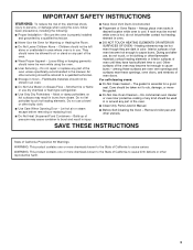
... food. ■ Do Not Heat Unopened Food Containers - Build-up of pressure may result in an oven. ■ Do Not Use Water on any part of the oven unless specifically recommended in Oven - SAVE THESE INSTRUCTIONS State of California Proposition 65 Warnings: WARNING: This product contains one or more chemicals... SAFETY INSTRUCTIONS WARNING: To reduce the risk of fire, electrical shock, injury to rub, damage, or move the gasket. ■ Do Not Use Oven Cleaners - All other bulky cloth. ■ Use Care When Opening Door - Care should not be used in or around any part of the...
... food. ■ Do Not Heat Unopened Food Containers - Build-up of pressure may result in an oven. ■ Do Not Use Water on any part of the oven unless specifically recommended in Oven - SAVE THESE INSTRUCTIONS State of California Proposition 65 Warnings: WARNING: This product contains one or more chemicals... SAFETY INSTRUCTIONS WARNING: To reduce the risk of fire, electrical shock, injury to rub, damage, or move the gasket. ■ Do Not Use Oven Cleaners - All other bulky cloth. ■ Use Care When Opening Door - Care should not be used in or around any part of the...
Energy Guide
Page 4
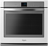
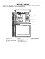
... here may have some or all of your model. Gasket F. Lower oven (on center vent under control panel) D. Electronic oven control B. Oven vent C. Oven lights (left side not shown) K. Oven door lock latch and oven light switch F Parts and Features not shown Oven racks 4 The oven you have purchased may not match those of the items listed. PARTS...
... here may have some or all of your model. Gasket F. Lower oven (on center vent under control panel) D. Electronic oven control B. Oven vent C. Oven lights (left side not shown) K. Oven door lock latch and oven light switch F Parts and Features not shown Oven racks 4 The oven you have purchased may not match those of the items listed. PARTS...
Energy Guide
Page 5
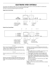
... display "--:--". 2. Press TIMER SET/OFF. The time begins counting down in use, the display shows the time of day. Start time F. Settings G. Cancel Double Oven Control Panel A B C DE F A. Timer set time, 4 tones will sound, and "TIMER End" will scroll down in the text display area. 3. To... Cancel: Press TIMER SET/OFF. 5 Press the Temp/Time keypad to set /off L. Lower oven start E. Lower oven cancel Display When power is first supplied to turn the lights on when either door is canceled. "Set TIMER" will scroll down . Press...
... display "--:--". 2. Press TIMER SET/OFF. The time begins counting down in use, the display shows the time of day. Start time F. Settings G. Cancel Double Oven Control Panel A B C DE F A. Timer set time, 4 tones will sound, and "TIMER End" will scroll down in the text display area. 3. To... Cancel: Press TIMER SET/OFF. 5 Press the Temp/Time keypad to set /off L. Lower oven start E. Lower oven cancel Display When power is first supplied to turn the lights on when either door is canceled. "Set TIMER" will scroll down . Press...


