Owners Manual
Page 1
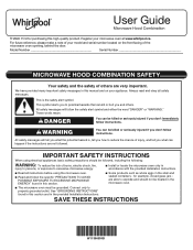
... outlet. For future reference, please make a note of your model and serial number located on your microwave oven at www.whirlpool.ca. IMPORTANT SAFETY INSTRUCTIONS When using the microwave oven. I Read and follow instructions. for purchasing this high-quality product. ...See "GROUNDING INSTRUCTIONS" found in accordance with the provided Installation Instructions. All safety messages will tell you what can be killed or seriously injured if you and others are very important...
... outlet. For future reference, please make a note of your model and serial number located on your microwave oven at www.whirlpool.ca. IMPORTANT SAFETY INSTRUCTIONS When using the microwave oven. I Read and follow instructions. for purchasing this high-quality product. ...See "GROUNDING INSTRUCTIONS" found in accordance with the provided Installation Instructions. All safety messages will tell you what can be killed or seriously injured if you and others are very important...
Owners Manual
Page 3
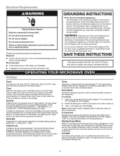
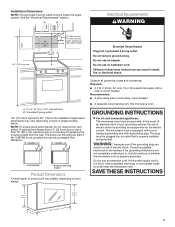
Electrical Requirements WARNING GROUNDING INSTRUCTIONS Electrical Shock Hazard Plug into an outlet that is properly installed and grounded. The microwave oven is pressed, deactivate demo mode, display "dOff" for 5 seconds to turn demo mode on the magnetron. ...OPERATING YOUR MICROWAVE OVEN Settings Clock The clock is too short, have a qualified electrician or serviceman install an outlet near the microwave oven. Choose the speed you want. Tones Open door, press and hold number keypad "3" for 5 seconds, "d" icon ...
Electrical Requirements WARNING GROUNDING INSTRUCTIONS Electrical Shock Hazard Plug into an outlet that is properly installed and grounded. The microwave oven is pressed, deactivate demo mode, display "dOff" for 5 seconds to turn demo mode on the magnetron. ...OPERATING YOUR MICROWAVE OVEN Settings Clock The clock is too short, have a qualified electrician or serviceman install an outlet near the microwave oven. Choose the speed you want. Tones Open door, press and hold number keypad "3" for 5 seconds, "d" icon ...
Owners Manual
Page 4
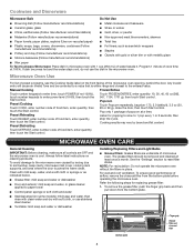
... clean. If dish becomes hot and the water stays cool, do not use stainless steel cleaner ■■ Turntable: mild soap and water or dishwasher Installing/Replacing Filters and Light Bulbs ■■ Grease filters: Grease filters are OFF and the microwave oven is within range and closest to enter power...
... clean. If dish becomes hot and the water stays cool, do not use stainless steel cleaner ■■ Turntable: mild soap and water or dishwasher Installing/Replacing Filters and Light Bulbs ■■ Grease filters: Grease filters are OFF and the microwave oven is within range and closest to enter power...
Owners Manual
Page 8
... For one year from state to state or province to correct improper product maintenance or installation, installation not in -home repair. Commercial, non-residential, multiple-family use, or use with the product, Whirlpool Corporation or Whirlpool Canada LP (hereafter "Whirlpool") will be provided by the customer. Service to province. 03/17 Defects or damage caused...
... For one year from state to state or province to correct improper product maintenance or installation, installation not in -home repair. Commercial, non-residential, multiple-family use, or use with the product, Whirlpool Corporation or Whirlpool Canada LP (hereafter "Whirlpool") will be provided by the customer. Service to province. 03/17 Defects or damage caused...
Specification Sheet
Page 1
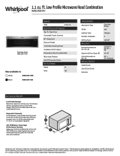
... of Speeds Venting Type Dimensions Product Dimensions (H x W x D) Depth with Door Open 90° Cutout Dimensions (W x D) Reference Material Install Guide Use & Care Guide Warranty Over-theRange 400 Halogen 3 Updraft 10-5/16" x 29-7/8" x 18" 42-1/8" 30" x 12" minimum...169; 2020. WML55011HSpecSheetV01. Low Profile Microwave Hood Combination WML55011H Stainless Steel WML55011HS Also available in the U.S.A. ft. Printed in : White WML55011HW Black WML55011HB Capacity Total 1.1 cu. For complete details, see Installation Instructions packed with 400 CFM motor class high performance...
... of Speeds Venting Type Dimensions Product Dimensions (H x W x D) Depth with Door Open 90° Cutout Dimensions (W x D) Reference Material Install Guide Use & Care Guide Warranty Over-theRange 400 Halogen 3 Updraft 10-5/16" x 29-7/8" x 18" 42-1/8" 30" x 12" minimum...169; 2020. WML55011HSpecSheetV01. Low Profile Microwave Hood Combination WML55011H Stainless Steel WML55011HS Also available in the U.S.A. ft. Printed in : White WML55011HW Black WML55011HB Capacity Total 1.1 cu. For complete details, see Installation Instructions packed with 400 CFM motor class high performance...
Installation Instructions
Page 1
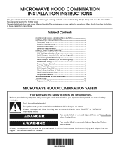
...Stud(s 5 Prepare Upper Cabinet 7 Mark Rear Wall 8 Drill Holes in these installation instructions. This symbol alerts you to Wall 9 Install the Microwave Oven 9 Complete Installation 10 VENTING DESIGN SPECIFICATIONS 11 ASSISTANCE 12 Replacement Parts 12 MICROWAVE HOOD COMBINATION SAFETY Your... read and obey all safety messages. W11359126A MICROWAVE HOOD COMBINATION INSTALLATION INSTRUCTIONS This product is the safety alert symbol. All safety messages will follow instructions. See the "Installation Requirements" section for use above electric or gas cooking products ...
...Stud(s 5 Prepare Upper Cabinet 7 Mark Rear Wall 8 Drill Holes in these installation instructions. This symbol alerts you to Wall 9 Install the Microwave Oven 9 Complete Installation 10 VENTING DESIGN SPECIFICATIONS 11 ASSISTANCE 12 Replacement Parts 12 MICROWAVE HOOD COMBINATION SAFETY Your... read and obey all safety messages. W11359126A MICROWAVE HOOD COMBINATION INSTALLATION INSTRUCTIONS This product is the safety alert symbol. All safety messages will follow instructions. See the "Installation Requirements" section for use above electric or gas cooking products ...
Installation Instructions
Page 2
...;■ 3/4" (1.9 cm) hole saw compound ■■ Duct tape Parts supplied For information on model, grease filter and charcoal filter may be installed. hole drill bit for wall or ro venting) J. A B C D E FG H Materials Needed Standard fittings for cooking. Location Requirements IMPORTANT...) diam. NOTE: The hardware items listed here are not designed to Round Transition" illustration in the "Venting Design Specifications" section. See the "Installation Dimensions" illustration. ■■ Minimum one 2" x 4" (5.1 cm x 10.16 cm) wood wall stud and minimum 3/8" (9.5 mm) ...
...;■ 3/4" (1.9 cm) hole saw compound ■■ Duct tape Parts supplied For information on model, grease filter and charcoal filter may be installed. hole drill bit for wall or ro venting) J. A B C D E FG H Materials Needed Standard fittings for cooking. Location Requirements IMPORTANT...) diam. NOTE: The hardware items listed here are not designed to Round Transition" illustration in the "Venting Design Specifications" section. See the "Installation Dimensions" illustration. ■■ Minimum one 2" x 4" (5.1 cm x 10.16 cm) wood wall stud and minimum 3/8" (9.5 mm) ...
Installation Instructions
Page 3
... codes and ordinances. WARNING: Improper use of electric shock. Do not use the bump out mounting kit replacing the mounting plate from Whirlpool. 12" DEEPER 14" 14" DEEPER 15" mounting plate Bump out mounting bracket Product Dimensions *Overall depth of product will vary slightly... depending on type of electric shock by providing an escape wire for 60" (152.4 cm) installation height exact dimensions may vary depending on door design. See the "Electrical Requirements" section. Observe all cord connected appliances: The microwave ...
... codes and ordinances. WARNING: Improper use of electric shock. Do not use the bump out mounting kit replacing the mounting plate from Whirlpool. 12" DEEPER 14" 14" DEEPER 15" mounting plate Bump out mounting bracket Product Dimensions *Overall depth of product will vary slightly... depending on type of electric shock by providing an escape wire for 60" (152.4 cm) installation height exact dimensions may vary depending on door design. See the "Electrical Requirements" section. Observe all cord connected appliances: The microwave ...
Installation Instructions
Page 4
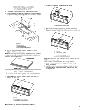
... front of microwave oven B. Position the damper assembly on the damper plate. Sheet metal screw 5/32" x 5/16" (4 mm x 8 mm) 3. Roof Venting Installation Only 1. Damper plate 4 Back of the microwave oven and lift up. Screws B. Go to the venting system. A BC D Wall Venting...another location where wall or roof venting may be made to section "Locate Wall Stud(s)". NOTE: Skip below sections if you are using recirculation installations. Check that the damper blade hinge is set for wall venting only) 1. Using diagonal wire cutting pliers, gently snip out the rectangular ...
... front of microwave oven B. Position the damper assembly on the damper plate. Sheet metal screw 5/32" x 5/16" (4 mm x 8 mm) 3. Roof Venting Installation Only 1. Damper plate 4 Back of the microwave oven and lift up. Screws B. Go to the venting system. A BC D Wall Venting...another location where wall or roof venting may be made to section "Locate Wall Stud(s)". NOTE: Skip below sections if you are using recirculation installations. Check that the damper blade hinge is set for wall venting only) 1. Using diagonal wire cutting pliers, gently snip out the rectangular ...
Installation Instructions
Page 5
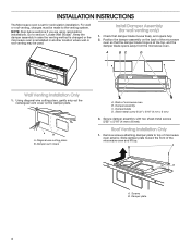
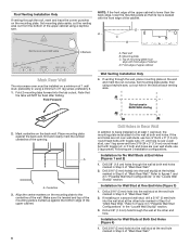
...NOTE: If no wall studs exist within the opening , do not install the microwave oven. Mark the center of the microwave oven 3. See illustrations in "Possible Wall Stud Configurations." 1. Install Damper Assembly (for Wall and Roof venting, remove the charcoal filter ...for both of airflow, for roof venting only) 1. Screws J. Recirculation vent covers C. Damper blade C. Charcoal Filter Grease Filter Vent Cover Installation (for future recirculation vent installation. 5 Keep C for step 2 use. Using a stud finder, locate the edges of microwave oven so that damper blade moves freely...
...NOTE: If no wall studs exist within the opening , do not install the microwave oven. Mark the center of the microwave oven 3. See illustrations in "Possible Wall Stud Configurations." 1. Install Damper Assembly (for Wall and Roof venting, remove the charcoal filter ...for both of airflow, for roof venting only) 1. Screws J. Recirculation vent covers C. Damper blade C. Charcoal Filter Grease Filter Vent Cover Installation (for future recirculation vent installation. 5 Keep C for step 2 use. Using a stud finder, locate the edges of microwave oven so that damper blade moves freely...
Installation Instructions
Page 6
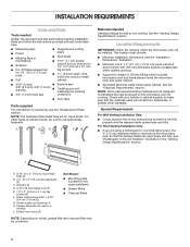
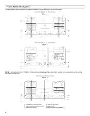
... 2 B C A A REAR WALL REAR WALL E E D F NOTE: If wall studs is within 6" (15.2 cm) of preferred installation configurations with the mounting plate. Cabinet opening vertical centerline C. Holes for lag screws E. Support tabs F. Mounting plate center markers 6 Possible Wall Stud... Configurations These depictions show examples of the vertical centerline (see "Mark Rear Wall" section), only recirculation or roof venting installation can be done. No Wall Studs at End Holes Figure 1 B C C D D A A REAR WALL REAR WALL E E F No Wall...
... 2 B C A A REAR WALL REAR WALL E E D F NOTE: If wall studs is within 6" (15.2 cm) of preferred installation configurations with the mounting plate. Cabinet opening vertical centerline C. Holes for lag screws E. Support tabs F. Mounting plate center markers 6 Possible Wall Stud... Configurations These depictions show examples of the vertical centerline (see "Mark Rear Wall" section), only recirculation or roof venting installation can be done. No Wall Studs at End Holes Figure 1 B C C D D A A REAR WALL REAR WALL E E F No Wall...
Installation Instructions
Page 7
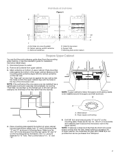
... supply cord bushing needs to be purchased from the rear wall to outlet. 2. Wall Studs at points "D" and "E" on mounting plate) B. See below install steps: 1. D G E t NOTE: If upper cabinet is maintained. NOTE: If replacing a range hood that the holes cut the holes of the... microwave oven (as shown. Make sure the 103⁄4" (27.3 cm) dimension from Whirlpool. 7 Mounting plate center markers Prepare Upper Cabinet You can be installed around the supply cord hole as installed) has a partial wall covering (for lag screws E. Place mounting plate against the rear...
... supply cord bushing needs to be purchased from the rear wall to outlet. 2. Wall Studs at points "D" and "E" on mounting plate) B. See below install steps: 1. D G E t NOTE: If upper cabinet is maintained. NOTE: If replacing a range hood that the holes cut the holes of the... microwave oven (as shown. Make sure the 103⁄4" (27.3 cm) dimension from Whirlpool. 7 Mounting plate center markers Prepare Upper Cabinet You can be installed around the supply cord hole as installed) has a partial wall covering (for lag screws E. Place mounting plate against the rear...
Installation Instructions
Page 8
...plate aside, then using a minimum of the cabinet. Refer to Figure 3 in "Possible Wall Stud Configurations" in the wall at End Holes (Figures 1 and 2) 1. Installation for No Wall Studs at back venting area. if 1 end hole is over a wall stud, use 1 lag screw and one 3/16-24 x 3" (7.6 cm) ... Stud Configurations" in Step 3 of the upper cabinet is lower than the back edge, lower the mounting plate so that the tabs will NOT be installed on at both end holes are over wall studs, use 2 lag screws. Top of cabinet D. D A C B 4 Corners REAR WALL REAR WALL Mark Rear...
...plate aside, then using a minimum of the cabinet. Refer to Figure 3 in "Possible Wall Stud Configurations" in the wall at End Holes (Figures 1 and 2) 1. Installation for No Wall Studs at back venting area. if 1 end hole is over a wall stud, use 1 lag screw and one 3/16-24 x 3" (7.6 cm) ... Stud Configurations" in Step 3 of the upper cabinet is lower than the back edge, lower the mounting plate so that the tabs will NOT be installed on at both end holes are over wall studs, use 2 lag screws. Top of cabinet D. D A C B 4 Corners REAR WALL REAR WALL Mark Rear...
Installation Instructions
Page 9
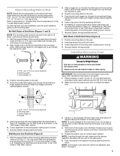
...insert a 3/16-24 x 3" (7.6 cm) round-head bolt through the end hole that fits over the 5/8" (1.6 cm) hole drilled in Step 3 of "Installation for the toggle nut to go through both end holes. 3. With the support tabs of the mounting plate facing forward, insert 3/16-24 x 3" (7.6 cm)...NOTE: If microwave oven does not need to make sure toggle nut has opened against drywall. 5. B A C A. 3/16 - 24 x 3" (7.6 cm) round-head bolt B. Install the Microwave Oven WARNING Excessive Weight Hazard Use two or more people, lift microwave oven and hang it is the heavy side. Check alignment of...
...insert a 3/16-24 x 3" (7.6 cm) round-head bolt through the end hole that fits over the 5/8" (1.6 cm) hole drilled in Step 3 of "Installation for the toggle nut to go through both end holes. 3. With the support tabs of the mounting plate facing forward, insert 3/16-24 x 3" (7.6 cm)...NOTE: If microwave oven does not need to make sure toggle nut has opened against drywall. 5. B A C A. 3/16 - 24 x 3" (7.6 cm) round-head bolt B. Install the Microwave Oven WARNING Excessive Weight Hazard Use two or more people, lift microwave oven and hang it is the heavy side. Check alignment of...
Installation Instructions
Page 10
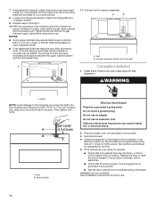
...3 through upper cabinet into microwave oven. Longer or shorter bolts are available at 100% power. Damper assembly (under vent) Compact A Complete Installation 1. Bolts NOTE: Avoid damage to follow these instructions can result in properly. Do not use . 10 If the microwave oven does not ...the operation of 1 minute at most hardware stores. ■■ Over-tightening bolts may require bolts longer or shorter than 3" (7.6 cm). Install filters. Bolt B. Do not use an extension cord. Replace the fuse or reset the circuit breaker. With the microwave oven centered, and with...
...3 through upper cabinet into microwave oven. Longer or shorter bolts are available at 100% power. Damper assembly (under vent) Compact A Complete Installation 1. Bolts NOTE: Avoid damage to follow these instructions can result in properly. Do not use . 10 If the microwave oven does not ...the operation of 1 minute at most hardware stores. ■■ Over-tightening bolts may require bolts longer or shorter than 3" (7.6 cm). Install filters. Bolt B. Do not use an extension cord. Replace the fuse or reset the circuit breaker. With the microwave oven centered, and with...
Installation Instructions
Page 11
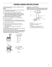
...spaces, such as spaces within the wall for optimal hood performance If venting through the roof, and rectangular-to vent air outside, unless using recirculation installation. If venting through the wall, be sure to -round transition is intended for wall venting only) D. A B C D E 3" (7.6 ... cap E. 3¹⁄4" x 10" to 6" (8.3 x 25.4 cm to 15.2 cm) rectangular to -Round Transition" illustration. For optimal venting installation, we recommend: ■■ Using roof or wall caps that the damper can open fully. See "Rectangular-to round transition piece F. Roof cap B....
...spaces, such as spaces within the wall for optimal hood performance If venting through the roof, and rectangular-to vent air outside, unless using recirculation installation. If venting through the wall, be sure to -round transition is intended for wall venting only) D. A B C D E 3" (7.6 ... cap E. 3¹⁄4" x 10" to 6" (8.3 x 25.4 cm to 15.2 cm) rectangular to -Round Transition" illustration. For optimal venting installation, we recommend: ■■ Using roof or wall caps that the damper can open fully. See "Rectangular-to round transition piece F. Roof cap B....
Installation Instructions
Page 12
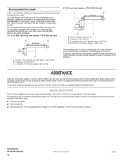
... addition, a rectangular 3" (7.6 cm) extension vent between the damper assembly and rectangular to round transition piece must be installed to -round transition piece = 5 ft (1.5 m) D. 2 ft (0.6 m) + 6 ft (1.8 m) straight = 8 ft (2.4 m) 2 ft (0.6 m) C A. Replacement Parts If any of the installation hardware needs to -round transition piece must not exceed the equivalent of available replacement parts. For best...
... addition, a rectangular 3" (7.6 cm) extension vent between the damper assembly and rectangular to round transition piece must be installed to -round transition piece = 5 ft (1.5 m) D. 2 ft (0.6 m) + 6 ft (1.8 m) straight = 8 ft (2.4 m) 2 ft (0.6 m) C A. Replacement Parts If any of the installation hardware needs to -round transition piece must not exceed the equivalent of available replacement parts. For best...


