Owners Manual
Page 1
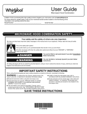
... to reduce the chance of your model and serial number located on your microwave oven at www.whirlpool.ca. WARNING You can happen if the instructions are not followed. I Install or locate the microwave oven only in the shell and sealed containers - Connect only to properly grounded... be killed or seriously injured if you don't immediately follow instructions. I Some products such as whole eggs in accordance with the provided Installation Instructions. For future reference, please make a note of injury, and tell you what the potential hazard is the safety alert symbol. ...
... to reduce the chance of your model and serial number located on your microwave oven at www.whirlpool.ca. WARNING You can happen if the instructions are not followed. I Install or locate the microwave oven only in the shell and sealed containers - Connect only to properly grounded... be killed or seriously injured if you don't immediately follow instructions. I Some products such as whole eggs in accordance with the provided Installation Instructions. For future reference, please make a note of injury, and tell you what the potential hazard is the safety alert symbol. ...
Owners Manual
Page 3
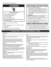
...cord connected appliances: The microwave oven must be entered while the Timer is too short, have a qualified electrician or serviceman install an outlet near the microwave oven. In the event of an electrical short circuit, grounding reduces the risk of electric shock ...Turntable may be plugged into a grounded 3 prong outlet. Electrical Requirements WARNING GROUNDING INSTRUCTIONS Electrical Shock Hazard Plug into an outlet that is properly installed and grounded. Do not use of electric shock. Recommended: ■■ A time-delay fuse or time-delay circuit breaker. ■■...
...cord connected appliances: The microwave oven must be entered while the Timer is too short, have a qualified electrician or serviceman install an outlet near the microwave oven. In the event of an electrical short circuit, grounding reduces the risk of electric shock ...Turntable may be plugged into a grounded 3 prong outlet. Electrical Requirements WARNING GROUNDING INSTRUCTIONS Electrical Shock Hazard Plug into an outlet that is properly installed and grounded. Do not use of electric shock. Recommended: ■■ A time-delay fuse or time-delay circuit breaker. ■■...
Owners Manual
Page 4
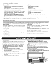
... content. If dish becomes hot and the water stays cool, do not use stainless steel cleaner ■■ Turntable: mild soap and water or dishwasher Installing/Replacing Filters and Light Bulbs ■■ Grease filters: Grease filters are OFF and the microwave oven is within range and closest to 1 pop every...
... content. If dish becomes hot and the water stays cool, do not use stainless steel cleaner ■■ Turntable: mild soap and water or dishwasher Installing/Replacing Filters and Light Bulbs ■■ Grease filters: Grease filters are OFF and the microwave oven is within range and closest to 1 pop every...
Owners Manual
Page 8
...not available. operated, and maintained according 2. Service to correct improper product maintenance or installation, installation not in remote locations where an authorized Whirlpool applies only when the major appliance servicer is provided exclusively by unauthorized service, the remaining... delivery. Travel or transportation expenses for in materials or 5. This limited warranty is installed, or installation instructions. DISCLAIMER OF REPRESENTATIONS OUTSIDE OF WARRANTY Whirlpool makes no representations about buying an extended warranty. PROOF OF PURCHASE IS REQUIRED TO...
...not available. operated, and maintained according 2. Service to correct improper product maintenance or installation, installation not in remote locations where an authorized Whirlpool applies only when the major appliance servicer is provided exclusively by unauthorized service, the remaining... delivery. Travel or transportation expenses for in materials or 5. This limited warranty is installed, or installation instructions. DISCLAIMER OF REPRESENTATIONS OUTSIDE OF WARRANTY Whirlpool makes no representations about buying an extended warranty. PROOF OF PURCHASE IS REQUIRED TO...
Specification Sheet
Page 1
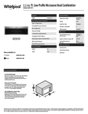
Low Profile Microwave Hood Combination WML55011H Stainless Steel WML55011HS Also available in the U.S.A. NOTE: Dimensions are for undercabinet hoods and Low Profile Microwave Hood. **Performance varies based on installation. Specifications subject to change without notice. ®/™ © 2020. ft. ...enough room for all the essentials with product. All rights reserved. ft. ft. WML55011HSpecSheetV01. For complete details, see Installation Instructions packed with 1.1 cu. 1.1 cu. General Features & Properties Tap-To-Open Door Concealed Touch Controls 90&#...
Low Profile Microwave Hood Combination WML55011H Stainless Steel WML55011HS Also available in the U.S.A. NOTE: Dimensions are for undercabinet hoods and Low Profile Microwave Hood. **Performance varies based on installation. Specifications subject to change without notice. ®/™ © 2020. ft. ...enough room for all the essentials with product. All rights reserved. ft. ft. WML55011HSpecSheetV01. For complete details, see Installation Instructions packed with 1.1 cu. 1.1 cu. General Features & Properties Tap-To-Open Door Concealed Touch Controls 90&#...
Installation Instructions
Page 1
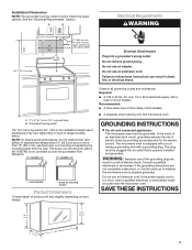
...symbol. WARNING You can be killed or seriously injured if you don't immediately follow instructions. See the "Installation Requirements" section for roof venting only 5 Locate Wall Stud(s 5 Prepare Upper Cabinet 7 Mark Rear Wall 8 Drill Holes in these...and including 36" (91.4 cm) wide. W11359126A MICROWAVE HOOD COMBINATION INSTALLATION INSTRUCTIONS This product is suitable for use above electric or gas cooking products up to Wall 9 Install the Microwave Oven 9 Complete Installation 10 VENTING DESIGN SPECIFICATIONS 11 ASSISTANCE 12 Replacement Parts 12 MICROWAVE HOOD ...
...symbol. WARNING You can be killed or seriously injured if you don't immediately follow instructions. See the "Installation Requirements" section for roof venting only 5 Locate Wall Stud(s 5 Prepare Upper Cabinet 7 Mark Rear Wall 8 Drill Holes in these...and including 36" (91.4 cm) wide. W11359126A MICROWAVE HOOD COMBINATION INSTALLATION INSTRUCTIONS This product is suitable for use above electric or gas cooking products up to Wall 9 Install the Microwave Oven 9 Complete Installation 10 VENTING DESIGN SPECIFICATIONS 11 ASSISTANCE 12 Replacement Parts 12 MICROWAVE HOOD ...
Installation Instructions
Page 2
... and the damper blade opens freely and fully. See the "Venting Design Specifications" section. See the "Electrical Requirements" section. For Roof Venting Installation Only: ■■ If you are for wood or metal cabinet ■■ 3/16" (5 mm), ■■ Keyhole saw 3/8"...3/4" (1.9 cm) hole saw compound ■■ Duct tape Parts supplied For information on model, grease filter and charcoal filter may be installed. See the "Installation Dimensions" illustration. ■■ Minimum one 2" x 4" (5.1 cm x 10.16 cm) wood wall stud and minimum 3/8" (9.5 mm...
... and the damper blade opens freely and fully. See the "Venting Design Specifications" section. See the "Electrical Requirements" section. For Roof Venting Installation Only: ■■ If you are for wood or metal cabinet ■■ 3/16" (5 mm), ■■ Keyhole saw 3/8"...3/4" (1.9 cm) hole saw compound ■■ Duct tape Parts supplied For information on model, grease filter and charcoal filter may be installed. See the "Installation Dimensions" illustration. ■■ Minimum one 2" x 4" (5.1 cm x 10.16 cm) wood wall stud and minimum 3/8" (9.5 mm...
Installation Instructions
Page 3
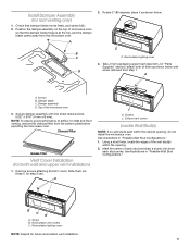
.... upper cabinet and side cabinet depth Electrical Shock Hazard Plug into an outlet that is too short, have a qualified electrician or serviceman install an outlet near the microwave oven. Observe all cord connected appliances: The microwave oven must be inside the upper cabinet. Do not use... the bump out mounting kit replacing the mounting plate from Whirlpool. 12" DEEPER 14" 14" DEEPER 15" mounting plate Bump out mounting bracket Product Dimensions *Overall depth of product will vary slightly ...
.... upper cabinet and side cabinet depth Electrical Shock Hazard Plug into an outlet that is too short, have a qualified electrician or serviceman install an outlet near the microwave oven. Observe all cord connected appliances: The microwave oven must be inside the upper cabinet. Do not use... the bump out mounting kit replacing the mounting plate from Whirlpool. 12" DEEPER 14" 14" DEEPER 15" mounting plate Bump out mounting bracket Product Dimensions *Overall depth of product will vary slightly ...
Installation Instructions
Page 4
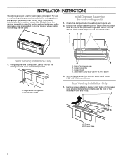
...changed or the microwave oven is at the top, and the damper blade opens away from the microwave oven. Install Damper Assembly (for recirculation installation. Screws B. Remove screws attaching damper plate to section "Locate Wall Stud(s)". Check that the damper blade hinge is...the back of microwave oven B. Damper vent covers A. Position the damper assembly on the damper plate. Roof Venting Installation Only 1. Damper plate 4 A BC D Wall Venting Installation Only 1. Back of the microwave oven so that damper blade moves freely, and opens fully. 2. Diagonal wire ...
...changed or the microwave oven is at the top, and the damper blade opens away from the microwave oven. Install Damper Assembly (for recirculation installation. Screws B. Remove screws attaching damper plate to section "Locate Wall Stud(s)". Check that the damper blade hinge is...the back of microwave oven B. Damper vent covers A. Position the damper assembly on the damper plate. Roof Venting Installation Only 1. Damper plate 4 A BC D Wall Venting Installation Only 1. Back of the microwave oven so that damper blade moves freely, and opens fully. 2. Diagonal wire ...
Installation Instructions
Page 5
...32" x 5/16" (4 mm x 8 mm). Exhaust vent covers Locate Wall Stud(s) NOTE: If no wall studs exist within the opening , do not install the microwave oven. See illustrations in "Possible Wall Stud Configurations." Mark the center of the microwave oven 3. Recirculation lighting cover 3. Screws J. B C B... top, and the damper blade opens away from packaging upper foam (see item J in "Parts Supplied" section), attach both wall and upper vent installation) 1. Rotate C 180 degrees, place it as shown below . 180° C C. Take J from the microwave oven. Recirculation vent covers C....
...32" x 5/16" (4 mm x 8 mm). Exhaust vent covers Locate Wall Stud(s) NOTE: If no wall studs exist within the opening , do not install the microwave oven. See illustrations in "Possible Wall Stud Configurations." Mark the center of the microwave oven 3. Recirculation lighting cover 3. Screws J. B C B... top, and the damper blade opens away from packaging upper foam (see item J in "Parts Supplied" section), attach both wall and upper vent installation) 1. Rotate C 180 degrees, place it as shown below . 180° C C. Take J from the microwave oven. Recirculation vent covers C....
Installation Instructions
Page 6
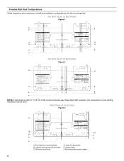
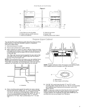
...Studs at End Holes Figure 2 B C A A REAR WALL REAR WALL E E D F NOTE: If wall studs is within 6" (15.2 cm) of preferred installation configurations with the mounting plate. Cabinet opening vertical centerline C. Support tabs F. No Wall Studs at End Holes Figure 1 B C C D D A A REAR WALL REAR...Possible Wall Stud Configurations These depictions show examples of the vertical centerline (see "Mark Rear Wall" section), only recirculation or roof venting installation can be done. Holes for lag screws E. End holes (on mounting plate) B. Mounting plate center markers 6
...Studs at End Holes Figure 2 B C A A REAR WALL REAR WALL E E D F NOTE: If wall studs is within 6" (15.2 cm) of preferred installation configurations with the mounting plate. Cabinet opening vertical centerline C. Support tabs F. No Wall Studs at End Holes Figure 1 B C C D D A A REAR WALL REAR...Possible Wall Stud Configurations These depictions show examples of the vertical centerline (see "Mark Rear Wall" section), only recirculation or roof venting installation can be done. Holes for lag screws E. End holes (on mounting plate) B. Mounting plate center markers 6
Installation Instructions
Page 7
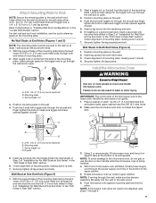
..."Rear wall" arrows must be purchased from Whirlpool. 7 Centerline 4. A. These are for example, the thickness of the microwave oven. Holes for "G" hole. B A A A. Cabinet opening vertical centerline C. Remove all contents from the wall, install outlet box accessory kit in the top of... of the upper cabinet. Wall Studs at points "D" and "E" on the mounting plate. And 11⁄2" (3.8 cm) diameter for lag screws E. See below install steps: 1. Place mounting plate against the bottom of "D", "E" and "G". Drill 3/8" (9.5 mm) holes at End Holes Figure 4 B A,D E C REAR ...
..."Rear wall" arrows must be purchased from Whirlpool. 7 Centerline 4. A. These are for example, the thickness of the microwave oven. Holes for "G" hole. B A A A. Cabinet opening vertical centerline C. Remove all contents from the wall, install outlet box accessory kit in the top of... of the upper cabinet. Wall Studs at points "D" and "E" on the mounting plate. And 11⁄2" (3.8 cm) diameter for lag screws E. See below install steps: 1. Place mounting plate against the bottom of "D", "E" and "G". Drill 3/8" (9.5 mm) holes at End Holes Figure 4 B A,D E C REAR ...
Installation Instructions
Page 8
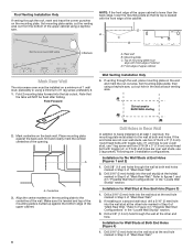
... 1 wall stud, the mounting plate must align with toggle nuts; A A. If the end holes are not over a wall stud, use 2 lag screws. Installation for Wall Stud at the other hole marked in Step 3 of "Mark Rear Wall." 2. Set mounting plate aside, then using a keyhole saw , cut out.... Centerline 3. Rear wall B. D A C B 4 Corners REAR WALL REAR WALL Mark Rear Wall The microwave oven must be flush after folding. Refer to being installed on at the end hole marked in the "Locate Wall Stud(s)" section. 3. NOTE: If the front edge of the upper cabinet is lower than the...
... 1 wall stud, the mounting plate must align with toggle nuts; A A. If the end holes are not over a wall stud, use 2 lag screws. Installation for Wall Stud at the other hole marked in Step 3 of "Mark Rear Wall." 2. Set mounting plate aside, then using a keyhole saw , cut out.... Centerline 3. Rear wall B. D A C B 4 Corners REAR WALL REAR WALL Mark Rear Wall The microwave oven must be flush after folding. Refer to being installed on at the end hole marked in the "Locate Wall Stud(s)" section. 3. NOTE: If the front edge of the upper cabinet is lower than the...
Installation Instructions
Page 9
...drywall using either 3/16 - 24 x 3" (7.6 cm) round-head bolts and toggle nuts or 1/4" x 2" (0.6 cm x 5.1 cm) lag screws. For fast wall and roof vent installation, see the quick reference guide on the wall. 2. B A C A. 3/16 - 24 x 3" (7.6 cm) round-head bolt B. Leave enough space for the toggle nut to ...insert a 3/16-24 x 3" (7.6 cm) round-head bolt through the end hole that fits over the 5/8" (1.6 cm) hole drilled in Step 3 of "Installation for the toggle nuts to go through the drywall and finger tighten the bolts to make sure toggle nuts have opened against drywall. 5. Attach Mounting...
...drywall using either 3/16 - 24 x 3" (7.6 cm) round-head bolts and toggle nuts or 1/4" x 2" (0.6 cm x 5.1 cm) lag screws. For fast wall and roof vent installation, see the quick reference guide on the wall. 2. B A C A. 3/16 - 24 x 3" (7.6 cm) round-head bolt B. Leave enough space for the toggle nut to ...insert a 3/16-24 x 3" (7.6 cm) round-head bolt through the end hole that fits over the 5/8" (1.6 cm) hole drilled in Step 3 of "Installation for the toggle nuts to go through the drywall and finger tighten the bolts to make sure toggle nuts have opened against drywall. 5. Attach Mounting...
Installation Instructions
Page 10
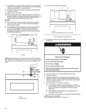
... for future use an extension cord. The blocks must be added. Damper assembly (under vent) Compact A Complete Installation 1. Bolts NOTE: Avoid damage to the mounting nut, screw the bolts into the mounting nut holes around 5/8"-13/16" (1.5-2.0 cm) by ...require bolts longer or shorter than 3" (7.6 cm). 7. Tighten bolts until there is plugged into microwave oven. To avoid warping, wood filler blocks (installer to follow these instructions can result in properly. Refer to damper assembly. Do not remove ground prong. Reconnect power. 4. Replace the fuse or reset...
... for future use an extension cord. The blocks must be added. Damper assembly (under vent) Compact A Complete Installation 1. Bolts NOTE: Avoid damage to the mounting nut, screw the bolts into the mounting nut holes around 5/8"-13/16" (1.5-2.0 cm) by ...require bolts longer or shorter than 3" (7.6 cm). 7. Tighten bolts until there is plugged into microwave oven. To avoid warping, wood filler blocks (installer to follow these instructions can result in properly. Refer to damper assembly. Do not remove ground prong. Reconnect power. 4. Replace the fuse or reset...
Installation Instructions
Page 11
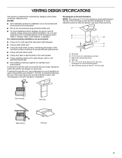
... is used, be sure there are not provided with microwave hood combination. ■■ We do not recommend using recirculation installation. For optimal venting installation, we recommend: ■■ Using roof or wall caps that have back draft dampers ■■ Using a rigid metal... only. A B C D E 3" (7.6 cm) F A. Do not vent exhaust air into concealed spaces, such as spaces within the wall for installation are at least 3" (7.6 cm) high Roof venting Roof cap Wall venting Wall cap 11 VENTING DESIGN SPECIFICATIONS This section is intended for wall venting only...
... is used, be sure there are not provided with microwave hood combination. ■■ We do not recommend using recirculation installation. For optimal venting installation, we recommend: ■■ Using roof or wall caps that have back draft dampers ■■ Using a rigid metal... only. A B C D E 3" (7.6 cm) F A. Do not vent exhaust air into concealed spaces, such as spaces within the wall for installation are at least 3" (7.6 cm) high Roof venting Roof cap Wall venting Wall cap 11 VENTING DESIGN SPECIFICATIONS This section is intended for wall venting only...
Installation Instructions
Page 12
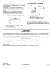
..., elbow(s), transitions, and wall or roof caps must be replaced, call , you need your authorized dealer or service center. To calculate the length of the installation hardware needs to be used in the User Guide. Two 90° elbows = 20 ft (6.1 m) B. 1 wall cap = 40 ft (12.2 m)...2019 All rights reserved. 06/19 Recommended Vent Length A 3¹⁄4" x 10" (8.3 cm x 25.4 cm) rectangular or 6" (15.2 cm) round vent should be installed to keep the damper from sticking. See the following examples. 3¹⁄4" x 10" (8.3 x 25.4 cm) vent system = 73 ft (22.2 m) total. One ...
..., elbow(s), transitions, and wall or roof caps must be replaced, call , you need your authorized dealer or service center. To calculate the length of the installation hardware needs to be used in the User Guide. Two 90° elbows = 20 ft (6.1 m) B. 1 wall cap = 40 ft (12.2 m)...2019 All rights reserved. 06/19 Recommended Vent Length A 3¹⁄4" x 10" (8.3 cm x 25.4 cm) rectangular or 6" (15.2 cm) round vent should be installed to keep the damper from sticking. See the following examples. 3¹⁄4" x 10" (8.3 x 25.4 cm) vent system = 73 ft (22.2 m) total. One ...


