Owners Manual
Page 3
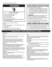
Do not use an adapter. Required: ■■ A 120 V, 60 Hz, AC-only, 15 A or 20 A electrical supply with Part 18 of cycle & timer tones will return to Standby Power mode and dim the display brightness after 2 minutes. Recommended: ■■ A time-delay fuse or ...
Do not use an adapter. Required: ■■ A 120 V, 60 Hz, AC-only, 15 A or 20 A electrical supply with Part 18 of cycle & timer tones will return to Standby Power mode and dim the display brightness after 2 minutes. Recommended: ■■ A time-delay fuse or ...
Owners Manual
Page 6
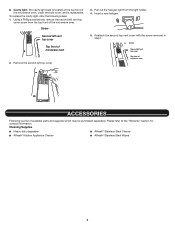
...; Cavity light: The cavity light bulb is located at the top front of the microwave oven, under the bulb cover, and is a list of available parts and supplies which may be purchased separately.
...; Cavity light: The cavity light bulb is located at the top front of the microwave oven, under the bulb cover, and is a list of available parts and supplies which may be purchased separately.
Owners Manual
Page 8
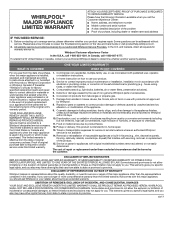
...telephone number ■ Model number and serial number ■ A clear, detailed description of the problem ■ Proof of non-genuine Whirlpool parts or accessories. labor to you call 1-800-807-6777. but not limited to, high salt concentrations, high moisture or humidity, or ...SHALL BE PRODUCT 10. Service must be addressed without service. Service or parts for warranty service to review the Troubleshooting section of product replacement, 6. Please take a few minutes to : Whirlpool Customer eXperience Center In the U.S.A., call 1-800-253-1301. to instructions ...
...telephone number ■ Model number and serial number ■ A clear, detailed description of the problem ■ Proof of non-genuine Whirlpool parts or accessories. labor to you call 1-800-807-6777. but not limited to, high salt concentrations, high moisture or humidity, or ...SHALL BE PRODUCT 10. Service must be addressed without service. Service or parts for warranty service to review the Troubleshooting section of product replacement, 6. Please take a few minutes to : Whirlpool Customer eXperience Center In the U.S.A., call 1-800-253-1301. to instructions ...
Installation Instructions
Page 1
...appliance. We have provided many important safety messages in these installation instructions. Table of Contents MICROWAVE HOOD COMBINATION SAFETY 1 INSTALLATION REQUIREMENTS 2 Tools and Parts 2 Location Requirements 2 Product Dimensions 3 Electrical Requirements 3 INSTALLATION INSTRUCTIONS 4 Wall Venting Installation Only 4 Install Damper Assembly (for wall venting only... Wall 9 Install the Microwave Oven 9 Complete Installation 10 VENTING DESIGN SPECIFICATIONS 11 ASSISTANCE 12 Replacement Parts 12 MICROWAVE HOOD COMBINATION SAFETY Your safety and the safety of others .
...appliance. We have provided many important safety messages in these installation instructions. Table of Contents MICROWAVE HOOD COMBINATION SAFETY 1 INSTALLATION REQUIREMENTS 2 Tools and Parts 2 Location Requirements 2 Product Dimensions 3 Electrical Requirements 3 INSTALLATION INSTRUCTIONS 4 Wall Venting Installation Only 4 Install Damper Assembly (for wall venting only... Wall 9 Install the Microwave Oven 9 Complete Installation 10 VENTING DESIGN SPECIFICATIONS 11 ASSISTANCE 12 Replacement Parts 12 MICROWAVE HOOD COMBINATION SAFETY Your safety and the safety of others .
Installation Instructions
Page 2
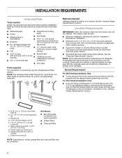
... drill bits ■■ Caulking gun and weatherproof caulking ■■ 3/4" (1.9 cm) hole saw compound ■■ Duct tape Parts supplied For information on model, grease filter and charcoal filter may be combined. 2 Location Requirements IMPORTANT: Check the opening . ■■...on the upper polyfoam) ■■ Grease filters ■■ Charcoal filters NOTE: Depending on reordering, see the "Replacement Parts" section. For other damages. See the "Venting Design Specifications" section. NOTE: Some cabinet and building materials are using a rectangular...
... drill bits ■■ Caulking gun and weatherproof caulking ■■ 3/4" (1.9 cm) hole saw compound ■■ Duct tape Parts supplied For information on model, grease filter and charcoal filter may be combined. 2 Location Requirements IMPORTANT: Check the opening . ■■...on the upper polyfoam) ■■ Grease filters ■■ Charcoal filters NOTE: Depending on reordering, see the "Replacement Parts" section. For other damages. See the "Venting Design Specifications" section. NOTE: Some cabinet and building materials are using a rectangular...
Installation Instructions
Page 3
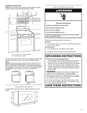
... properly grounded. Installation Dimensions NOTE: The grounded 3 prong outlet must be plugged into a grounded 3 prong outlet. The bump out mounting kit (part # W11185746) is equipped with a cord having a grounding wire with a fuse or circuit breaker Recommended: ■■ A time-delay fuse or... use an extension cord. See the "Electrical Requirements" section. Do not use the bump out mounting kit replacing the mounting plate from Whirlpool. 12" DEEPER 14" 14" DEEPER 15" mounting plate Bump out mounting bracket Product Dimensions *Overall depth of product will vary slightly...
... properly grounded. Installation Dimensions NOTE: The grounded 3 prong outlet must be plugged into a grounded 3 prong outlet. The bump out mounting kit (part # W11185746) is equipped with a cord having a grounding wire with a fuse or circuit breaker Recommended: ■■ A time-delay fuse or... use an extension cord. See the "Electrical Requirements" section. Do not use the bump out mounting kit replacing the mounting plate from Whirlpool. 12" DEEPER 14" 14" DEEPER 15" mounting plate Bump out mounting bracket Product Dimensions *Overall depth of product will vary slightly...
Installation Instructions
Page 5
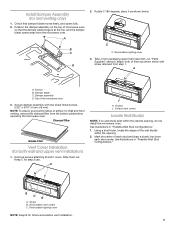
.... Top of each stud and draw a plumb line down each stud center. Secure damper assembly with screw removed from packaging upper foam (see item J in "Parts Supplied" section), attach both wall and upper vent installation) 1. See illustrations in "Possible Wall Stud Configurations." Screw B. Position the damper assembly on the top of...
.... Top of each stud and draw a plumb line down each stud center. Secure damper assembly with screw removed from packaging upper foam (see item J in "Parts Supplied" section), attach both wall and upper vent installation) 1. See illustrations in "Possible Wall Stud Configurations." Screw B. Position the damper assembly on the top of...
Installation Instructions
Page 7
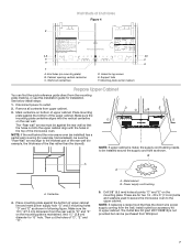
...). NOTE: If the wall behind the microwave oven (as installed) has a partial wall covering (for installation. The Outlet Box Kit (part #W11082816) is not provided but can find the quick reference guide direct from the mounting plate marking, or use this installation guide for ...1⁄4 - 20 x 3" (7.6 cm) bolts and washers used to secure the microwave oven to outlet. 2. B A A A. Remove all contents from Whirlpool. 7 And 11⁄2" (3.8 cm) diameter for lag screws E. Mounting plate center markers Prepare Upper Cabinet You can be installed around the supply cord hole as...
...). NOTE: If the wall behind the microwave oven (as installed) has a partial wall covering (for installation. The Outlet Box Kit (part #W11082816) is not provided but can find the quick reference guide direct from the mounting plate marking, or use this installation guide for ...1⁄4 - 20 x 3" (7.6 cm) bolts and washers used to secure the microwave oven to outlet. 2. B A A A. Remove all contents from Whirlpool. 7 And 11⁄2" (3.8 cm) diameter for lag screws E. Mounting plate center markers Prepare Upper Cabinet You can be installed around the supply cord hole as...
Installation Instructions
Page 12
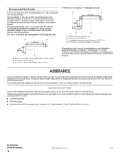
...8 ft (2.4 m) 2 ft (0.6 m) C A. Following is located behind the door. ■■ Damper assembly ■■ Mounting plate ■■ Mounting Screw Kit (includes parts A through G in "Parts Supplied" in the system. When you call us at our toll-free number listed in the User Guide. If you will need the microwave... must be installed to -round transition piece must not exceed the equivalent of 140 ft (42.7 m) for equivalent lengths. Replacement Parts If any of the microwave oven. For best performance, use no more than three 90° elbows. Both numbers can be ...
...8 ft (2.4 m) 2 ft (0.6 m) C A. Following is located behind the door. ■■ Damper assembly ■■ Mounting plate ■■ Mounting Screw Kit (includes parts A through G in "Parts Supplied" in the system. When you call us at our toll-free number listed in the User Guide. If you will need the microwave... must be installed to -round transition piece must not exceed the equivalent of 140 ft (42.7 m) for equivalent lengths. Replacement Parts If any of the microwave oven. For best performance, use no more than three 90° elbows. Both numbers can be ...


