
Installation Instructions
Page 1
... and obey all safety messages. This is , tell you how to Wall 8 Prepare Upper Cabinet 8 Install Damper Assembly 9 Install the Microwave Oven 9 Complete Installation 10 VENTING DESIGN SPECIFICATIONS 11 ASSISTANCE 12 Replacement Parts 12 Accessories 12 MICROWAVE HOOD COMBINATION SAFETY Your safety and... chance of injury, and tell you and others are not followed. We have provided many important safety messages in these installation instructions. WARNING You can happen if the instructions are very important. The appearance of others . W10247296B All safety messages will...
... and obey all safety messages. This is , tell you how to Wall 8 Prepare Upper Cabinet 8 Install Damper Assembly 9 Install the Microwave Oven 9 Complete Installation 10 VENTING DESIGN SPECIFICATIONS 11 ASSISTANCE 12 Replacement Parts 12 Accessories 12 MICROWAVE HOOD COMBINATION SAFETY Your safety and... chance of injury, and tell you and others are not followed. We have provided many important safety messages in these installation instructions. WARNING You can happen if the instructions are very important. The appearance of others . W10247296B All safety messages will...

Installation Instructions
Page 2
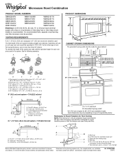
... follow the instructions provided with your builder or cabinet supplier to make sure there is at least 6" (15.2 cm) of wall structures, be installed. hole drill ■ No. 2 Phillips screwdriver bit for wood or metal ■ No. 3 Phillips screwdriver for weight of the cardboard packaging. ... the side and refer to exist above the microwave oven so that the vent fits properly, and the damper blade opens freely and fully. See "Installation Dimensions" illustration. ■ Minimum one 2" x 4" (50.8 x 101.6 mm) wood wall stud and minimum 3/8" (10 mm) thickness drywall or plaster/...
... follow the instructions provided with your builder or cabinet supplier to make sure there is at least 6" (15.2 cm) of wall structures, be installed. hole drill ■ No. 2 Phillips screwdriver bit for wood or metal ■ No. 3 Phillips screwdriver for weight of the cardboard packaging. ... the side and refer to exist above the microwave oven so that the vent fits properly, and the damper blade opens freely and fully. See "Installation Dimensions" illustration. ■ Minimum one 2" x 4" (50.8 x 101.6 mm) wood wall stud and minimum 3/8" (10 mm) thickness drywall or plaster/...

Installation Instructions
Page 3
... can result in a risk of electric shock. A. 2" x 4" wall stud B. Grounded 3 prong outlet *30" (76.2 cm) is properly installed and grounded. Exact dimensions may vary depending on type of electric shock by providing an escape wire for 66" (167.6 cm...result in death, fire, or electrical shock. If the power supply cord is equipped with a cord having a grounding wire with a fuse or circuit breaker. Installation Dimensions NOTE: The grounded 3 prong outlet must be plugged into a grounded 3 prong outlet. See "Electrical Requirements" section. A B Electrical Requirements WARNING 66...
... can result in a risk of electric shock. A. 2" x 4" wall stud B. Grounded 3 prong outlet *30" (76.2 cm) is properly installed and grounded. Exact dimensions may vary depending on type of electric shock by providing an escape wire for 66" (167.6 cm...result in death, fire, or electrical shock. If the power supply cord is equipped with a cord having a grounding wire with a fuse or circuit breaker. Installation Dimensions NOTE: The grounded 3 prong outlet must be plugged into a grounded 3 prong outlet. See "Electrical Requirements" section. A B Electrical Requirements WARNING 66...

Installation Instructions
Page 4
... A A. Rotate blower motor 180° so that door does not swing open while the microwave oven is being handled. A B A. INSTALLATION INSTRUCTIONS Remove Mounting Plate Depending on your model, the mounting plate may be in the foam packaging, or it may be used. Remove any... reinstalled in case the venting method is changed, or the microwave oven is attached to the back of microwave oven exterior. Wall Venting Installation Only 1. Secure damper plate with 2 screws removed in Step 3. 7. Remove 2 screws attaching blower motor to the work surface, cover...
... A A. Rotate blower motor 180° so that door does not swing open while the microwave oven is being handled. A B A. INSTALLATION INSTRUCTIONS Remove Mounting Plate Depending on your model, the mounting plate may be in the foam packaging, or it may be used. Remove any... reinstalled in case the venting method is changed, or the microwave oven is attached to the back of microwave oven exterior. Wall Venting Installation Only 1. Secure damper plate with 2 screws removed in Step 3. 7. Remove 2 screws attaching blower motor to the work surface, cover...

Installation Instructions
Page 5
...." 5 Damper plate tabs D. Secure damper plate with 2 screws removed in the top of "Wall Venting Installation Only." Roof Venting Installation Only 1. D A. Repeat Step 3 from "Wall Venting Installation Only." 2. Lower blower motor back into the slots in Step 3 of the microwave oven. NOTE: If ... not correctly oriented, the 2 screws removed in Step 1 of microwave oven. Slots 8. Repeat Step 1 from "Wall Venting Installation Only." 4. Securely tighten screws. Reattach damper plate. A 6. Damper plate B. Reattach blower motor to the microwave oven. 7.
...." 5 Damper plate tabs D. Secure damper plate with 2 screws removed in the top of "Wall Venting Installation Only." Roof Venting Installation Only 1. D A. Repeat Step 3 from "Wall Venting Installation Only." 2. Lower blower motor back into the slots in Step 3 of the microwave oven. NOTE: If ... not correctly oriented, the 2 screws removed in Step 1 of microwave oven. Slots 8. Repeat Step 1 from "Wall Venting Installation Only." 4. Securely tighten screws. Reattach damper plate. A 6. Damper plate B. Reattach blower motor to the microwave oven. 7.

Installation Instructions
Page 6
... "Possible Wall Stud Configurations." End holes (on mounting plate) B. Support tabs F. Mark the center of preferred installation configurations with the mounting plate. Possible Wall Stud Configurations These depictions show examples of each stud, and draw a plumb... the vertical centerline (see "Mark Rear Wall" section), only recirculation or roof venting installation can be done. Wall stud centerlines D. See illustrations in "Possible Wall Stud Configurations." 2. Cabinet opening , do not install the microwave oven. 1. Locate Wall Stud(s) NOTE: If no wall studs exist within...
... "Possible Wall Stud Configurations." End holes (on mounting plate) B. Support tabs F. Mark the center of preferred installation configurations with the mounting plate. Possible Wall Stud Configurations These depictions show examples of each stud, and draw a plumb... the vertical centerline (see "Mark Rear Wall" section), only recirculation or roof venting installation can be done. Wall stud centerlines D. See illustrations in "Possible Wall Stud Configurations." 2. Cabinet opening , do not install the microwave oven. 1. Locate Wall Stud(s) NOTE: If no wall studs exist within...

Installation Instructions
Page 7
...wall stud centerline(s) drawn in Step 2 of "Locate Wall Stud(s)," and mark at the hole(s) marked in Rear Wall In addition to being installed on a minimum of 1 wall stud, preferably 2, using a minimum of the upper cabinet. 9. Centerline 2. NOTES: ■ If the ...The blackened holes in "Locate Wall Stud(s)" section), align the mounting plate center markers to complete the 12" x 4" (30.5 x 10.2 cm) rectangle. Wall Venting Installation Only Upper cabinet bottom ³⁄₈" (1 cm) 4" (10.2 cm) Centerline 6" (15.2 cm) 6" (15.2 cm) 8. Using measuring tape, measure out...
...wall stud centerline(s) drawn in Step 2 of "Locate Wall Stud(s)," and mark at the hole(s) marked in Rear Wall In addition to being installed on a minimum of 1 wall stud, preferably 2, using a minimum of the upper cabinet. 9. Centerline 2. NOTES: ■ If the ...The blackened holes in "Locate Wall Stud(s)" section), align the mounting plate center markers to complete the 12" x 4" (30.5 x 10.2 cm) rectangle. Wall Venting Installation Only Upper cabinet bottom ³⁄₈" (1 cm) 4" (10.2 cm) Centerline 6" (15.2 cm) 6" (15.2 cm) 8. Using measuring tape, measure out...

Installation Instructions
Page 8
...mm) hole into the upper cabinet align with toggle nut through the drywall, and finger tighten the bolt to open . 3. With the support tabs of "Installation for Wall Stud at the other end hole. Leave enough space for the toggle nuts to go through the end hole that fits over the... end hole marked in Rear Wall" section. 8 Upper-cabinet template D 10" (25.4 cm) F E 10" G (25.4 cm) C A 6. Position mounting plate on the wall. 2. If installing on the rear wall. Wall Studs at End Holes" in the "Drill Holes in Step 3 of the tiles rather than the drywall). 4. Push the 2 bolts...
...mm) hole into the upper cabinet align with toggle nut through the drywall, and finger tighten the bolt to open . 3. With the support tabs of "Installation for Wall Stud at the other end hole. Leave enough space for the toggle nuts to go through the end hole that fits over the... end hole marked in Rear Wall" section. 8 Upper-cabinet template D 10" (25.4 cm) F E 10" G (25.4 cm) C A 6. Position mounting plate on the wall. 2. If installing on the rear wall. Wall Studs at End Holes" in the "Drill Holes in Step 3 of the tiles rather than the drywall). 4. Push the 2 bolts...

Installation Instructions
Page 9
...area "G" on the template. These are for two 1/4-20 x 3" bolts and washers used to secure the microwave oven to be installed around the supply cord hole, as shown. Install Damper Assembly (for the power supply cord. Rotate microwave oven up toward upper cabinet. Metal cabinet B. Using a keyhole saw, ...Cut the 1¹⁄₂" (3.8 cm) diameter hole at points "D" and "E" on the template. This hole is being handled. Failure to move and install microwave oven. Using 2 or more people to do not grip or use the door or door handle while the microwave oven is for wall venting...
...area "G" on the template. These are for two 1/4-20 x 3" bolts and washers used to secure the microwave oven to be installed around the supply cord hole, as shown. Install Damper Assembly (for the power supply cord. Rotate microwave oven up toward upper cabinet. Metal cabinet B. Using a keyhole saw, ...Cut the 1¹⁄₂" (3.8 cm) diameter hole at points "D" and "E" on the template. This hole is being handled. Failure to move and install microwave oven. Using 2 or more people to do not grip or use the door or door handle while the microwave oven is for wall venting...

Installation Instructions
Page 10
...bolts until there is now complete. Sheet metal screw D. Plug microwave oven into a grounded 3 prong outlet. Reconnect power. 4. Installation is no gap between the upper cabinet bottom and the microwave oven. Adjust mounting plate and retighten screws. 9. Then secure with at... Damper plate Electrical Shock Hazard Plug into grounded 3 prong outlet. 3. Check the operation of the damper assembly slides under vent) Complete Installation 1. If the problem continues, call an electrician. ■ Check that the power supply cord is plugged into microwave oven. With the...
...bolts until there is now complete. Sheet metal screw D. Plug microwave oven into a grounded 3 prong outlet. Reconnect power. 4. Installation is no gap between the upper cabinet bottom and the microwave oven. Adjust mounting plate and retighten screws. 9. Then secure with at... Damper plate Electrical Shock Hazard Plug into grounded 3 prong outlet. 3. Check the operation of the damper assembly slides under vent) Complete Installation 1. If the problem continues, call an electrician. ■ Check that the power supply cord is plugged into microwave oven. With the...

Installation Instructions
Page 11
...; using duct tape to seal all joints in "Recommended Vent Length." See the examples in the vent system ■ using recirculation installation. Rectangular to round transition piece: 3¹⁄₄" x 10" to 6" = 5 ft (8.3 x 25.4 cm to Round... 3¹⁄₄" x 10" = 10 ft (8.3 x 25.4 cm = 3 m) 11 A B C D E 3" (7.6 cm) F A. NOTES: ■ Vent materials needed for installation are for architectural designer and builder/contractor reference only. See "Rectangular to 15.2 cm = 1.5 m) B. Roof cap B. 6" (15.2 cm) min. If venting through the roof, and...
...; using duct tape to seal all joints in "Recommended Vent Length." See the examples in the vent system ■ using recirculation installation. Rectangular to round transition piece: 3¹⁄₄" x 10" to 6" = 5 ft (8.3 x 25.4 cm to Round... 3¹⁄₄" x 10" = 10 ft (8.3 x 25.4 cm = 3 m) 11 A B C D E 3" (7.6 cm) F A. NOTES: ■ Vent materials needed for installation are for architectural designer and builder/contractor reference only. See "Rectangular to 15.2 cm = 1.5 m) B. Roof cap B. 6" (15.2 cm) min. If venting through the roof, and...

Installation Instructions
Page 12
...dealer or service center for details. Recommended Vent Length A 3¹⁄₄" x 10" (8.3 x 25.4 cm) rectangular or 6" (15.2 cm) round vent should be installed to use no more than three 90° elbows. Two 90° elbows = 20 ft (6.1 m) B. 1 wall cap = 40 ft (12.2 m) C. 1 ...a rectangular 3" (7.6 cm) extension vent between the damper assembly and rectangular to round transition piece must not exceed the equivalent of the installation hardware needs to round transition piece must be replaced, call us at our toll free number or visit our website listed in the "...
...dealer or service center for details. Recommended Vent Length A 3¹⁄₄" x 10" (8.3 x 25.4 cm) rectangular or 6" (15.2 cm) round vent should be installed to use no more than three 90° elbows. Two 90° elbows = 20 ft (6.1 m) B. 1 wall cap = 40 ft (12.2 m) C. 1 ...a rectangular 3" (7.6 cm) extension vent between the damper assembly and rectangular to round transition piece must not exceed the equivalent of the installation hardware needs to round transition piece must be replaced, call us at our toll free number or visit our website listed in the "...
Dimension Guide
Page 1
...ft (12.2 m) C. 2 ft (0.6 m) + 6 ft (1.8 m) straight = 8 ft (2.4 m) B C 3" (7.6 cm) D A. Elbow (for 66" (167.6 cm) installation height. Wall cap F E. 3 " x 10" to 6" (8.3 x 25.4 cm to 15.2 cm) rectangular to change materials and specifications without notice. It is recommended that the ...2 ft (0.6 m) C A. Vent extension piece, at least 3" (7.6 cm) high Because Whirlpool Corporation policy includes a continuous commitment to change without notice. For complete details, see Installation our products, we reserve the right to improve Dimensions are for each vent piece used . ...
...ft (12.2 m) C. 2 ft (0.6 m) + 6 ft (1.8 m) straight = 8 ft (2.4 m) B C 3" (7.6 cm) D A. Elbow (for 66" (167.6 cm) installation height. Wall cap F E. 3 " x 10" to 6" (8.3 x 25.4 cm to 15.2 cm) rectangular to change materials and specifications without notice. It is recommended that the ...2 ft (0.6 m) C A. Vent extension piece, at least 3" (7.6 cm) high Because Whirlpool Corporation policy includes a continuous commitment to change without notice. For complete details, see Installation our products, we reserve the right to improve Dimensions are for each vent piece used . ...
Warranty Information
Page 1
... located in materials or workmanship and is reported to Whirlpool within 30 days from the date of purchase. 6. Damage resulting from accident, alteration, misuse, abuse, fire, flood, acts of God, improper installation, installation not in accordance with electrical or plumbing codes, or... your major appliance for Factory Specified Parts and repair labor to correct defects in accordance with published installation instructions. 11. W10451742A SP PN W10458699A © 2012 Whirlpool Corporation. ITEMS EXCLUDED FROM WARRANTY This limited warranty does not cover: 1. Expenses for travel and ...
... located in materials or workmanship and is reported to Whirlpool within 30 days from the date of purchase. 6. Damage resulting from accident, alteration, misuse, abuse, fire, flood, acts of God, improper installation, installation not in accordance with electrical or plumbing codes, or... your major appliance for Factory Specified Parts and repair labor to correct defects in accordance with published installation instructions. 11. W10451742A SP PN W10458699A © 2012 Whirlpool Corporation. ITEMS EXCLUDED FROM WARRANTY This limited warranty does not cover: 1. Expenses for travel and ...
Use & Care Guide
Page 1
...for additional information. If you don't follow instructions. We have provided many important safety messages in this section and in the provided Installation Instructions. Microwave Hood Combination Safety Your safety and the safety of injury, and tell you what the potential hazard is the safety .... All safety messages will need assistance, call us at www.whirlpool.com for example, closed glass jars - You will tell you what can kill or hurt you how to excessive microwave energy: ■ Install or locate the microwave oven only in accordance with the provided...
...for additional information. If you don't follow instructions. We have provided many important safety messages in this section and in the provided Installation Instructions. Microwave Hood Combination Safety Your safety and the safety of injury, and tell you what the potential hazard is the safety .... All safety messages will need assistance, call us at www.whirlpool.com for example, closed glass jars - You will tell you what can kill or hurt you how to excessive microwave energy: ■ Install or locate the microwave oven only in accordance with the provided...
Use & Care Guide
Page 3
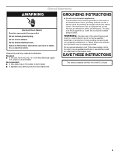
... grounded. Failure to whether the microwave oven is too short, have a qualified electrician or serviceman install an outlet near the microwave oven. WARNING: Improper use an extension cord. The microwave oven is equipped with a cord having a grounding wire with a fuse or ...
... grounded. Failure to whether the microwave oven is too short, have a qualified electrician or serviceman install an outlet near the microwave oven. WARNING: Improper use an extension cord. The microwave oven is equipped with a cord having a grounding wire with a fuse or ...
Use & Care Guide
Page 6
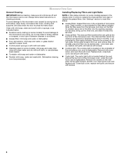
... water, then rinse with clean water and dry with screws. 6 Remove bulb cover screw, and open the bulb cover. Open bulb cover and replace bulb. Installing/Replacing Filters and Light Bulbs NOTE: A filter status indicator (on the vent grille, tilt the grille forward, lift it out. To reinstall, place the filter...
... water, then rinse with clean water and dry with screws. 6 Remove bulb cover screw, and open the bulb cover. Open bulb cover and replace bulb. Installing/Replacing Filters and Light Bulbs NOTE: A filter status indicator (on the vent grille, tilt the grille forward, lift it out. To reinstall, place the filter...
Use & Care Guide
Page 8
...from your home of your major appliance if it is installed in an inaccessible location or is not installed in materials or workmanship and is reported to view FAQs (Frequently Asked Questions), visit www.whirlpool.com. The removal and reinstallation of your major appliance ...damage results from defects in accordance with published installation instructions. 11. For assistance or service, call 1-800-253-1301. Service calls to correct the installation of your major appliance, to instruct you can find your authorized Whirlpool dealer to determine if another warranty applies. 9/...
...from your home of your major appliance if it is installed in an inaccessible location or is not installed in materials or workmanship and is reported to view FAQs (Frequently Asked Questions), visit www.whirlpool.com. The removal and reinstallation of your major appliance ...damage results from defects in accordance with published installation instructions. 11. For assistance or service, call 1-800-253-1301. Service calls to correct the installation of your major appliance, to instruct you can find your authorized Whirlpool dealer to determine if another warranty applies. 9/...
