Dimension Guide
Page 1
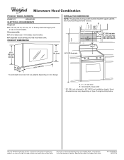
... dimensions may vary depending on door design. Grounded 3 prong outlet * 30" (76.2 cm) is typical for planning purposes only. PRODUCT DIMENSIONS INSTALLATION DIMENSIONS NOTE: The grounded 3 prong outlet must be inside the upper cabinet. Specifications subject to change without notice. Microwave Hood Combination PRODUCT MODEL NUMBERS WMH31017 WMH32519F ELECTRICAL REQUIREMENTS Required: ■■ A 120 volt, 60 Hz, AC only, 15- or 20-amp electrical supply with product. A. 2" x 4" wall...
... dimensions may vary depending on door design. Grounded 3 prong outlet * 30" (76.2 cm) is typical for planning purposes only. PRODUCT DIMENSIONS INSTALLATION DIMENSIONS NOTE: The grounded 3 prong outlet must be inside the upper cabinet. Specifications subject to change without notice. Microwave Hood Combination PRODUCT MODEL NUMBERS WMH31017 WMH32519F ELECTRICAL REQUIREMENTS Required: ■■ A 120 volt, 60 Hz, AC only, 15- or 20-amp electrical supply with product. A. 2" x 4" wall...
Warranty Information
Page 1
... use your retailer about the quality, durability, or need for service in materials or 5. WARRANTY SHALL BE PRODUCT 10. Travel or transportation expenses for service or repair of original purchase date is not available. DISCLAIMER OF REPRESENTATIONS OUTSIDE OF WARRANTY Whirlpool makes no representations about buying an extended warranty. house wiring, fuses or water inlet hoses). warranty period. 9. Proof of this warranty. This warranty gives you specific...
... use your retailer about the quality, durability, or need for service in materials or 5. WARRANTY SHALL BE PRODUCT 10. Travel or transportation expenses for service or repair of original purchase date is not available. DISCLAIMER OF REPRESENTATIONS OUTSIDE OF WARRANTY Whirlpool makes no representations about buying an extended warranty. house wiring, fuses or water inlet hoses). warranty period. 9. Proof of this warranty. This warranty gives you specific...
Use & Care Guide
Page 1
... the provided Installation Instructions. Connect only to excessive microwave energy: I Install or locate the microwave oven only in the provided Installation Instructions. These words mean: DANGER You can happen if the instructions are able to explode and should be followed, including the following: WARNING: To reduce the risk of your microwave oven at www.whirlpool.com. User Guide Microwave Hood Combination THANK YOU for example, closed glass jars are...
... the provided Installation Instructions. Connect only to excessive microwave energy: I Install or locate the microwave oven only in the provided Installation Instructions. These words mean: DANGER You can happen if the instructions are able to explode and should be followed, including the following: WARNING: To reduce the risk of your microwave oven at www.whirlpool.com. User Guide Microwave Hood Combination THANK YOU for example, closed glass jars are...
Use & Care Guide
Page 2
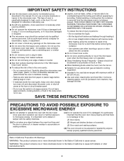
... hood, turn oven off, and disconnect the power cord, or shut off power at the fuse or circuit breaker panel. SAVE THESE INSTRUCTIONS PRECAUTIONS TO AVOID POSSIBLE EXPOSURE TO EXCESSIVE MICROWAVE ENERGY (a) Do not attempt to operate this microwave oven outdoors. This type of 36" (91.44 cm). - Remove wire twist-ties from heated surfaces. Grease should not be overheated beyond the boiling point without appearing to microwave energy. Carefully...
... hood, turn oven off, and disconnect the power cord, or shut off power at the fuse or circuit breaker panel. SAVE THESE INSTRUCTIONS PRECAUTIONS TO AVOID POSSIBLE EXPOSURE TO EXCESSIVE MICROWAVE ENERGY (a) Do not attempt to operate this microwave oven outdoors. This type of 36" (91.44 cm). - Remove wire twist-ties from heated surfaces. Grease should not be overheated beyond the boiling point without appearing to microwave energy. Carefully...
Use & Care Guide
Page 3
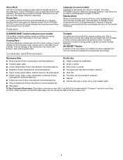
... display. Cook functions may also be entered while the Timer is properly grounded. Control Lock Activate to reach the Fan Timer submenu and select the setting. Options/Clock Ten options/settings may be adjusted: 1-Clock & Energy Save; 2-Scrolling Speed; 3-Sound; 4-Language; 5-Auto Vent Fan; 6-Filter Reset; 7-Fan Timer; 8-Light Timer; 9-Demo Mode; 10-Factory Reset Vent Fan Various speeds, ranging from the range or cooktop below the microwave oven gets too hot. Vent Timer: Set vent fan to run for exactly 30 minutes or to run for heat...
... display. Cook functions may also be entered while the Timer is properly grounded. Control Lock Activate to reach the Fan Timer submenu and select the setting. Options/Clock Ten options/settings may be adjusted: 1-Clock & Energy Save; 2-Scrolling Speed; 3-Sound; 4-Language; 5-Auto Vent Fan; 6-Filter Reset; 7-Fan Timer; 8-Light Timer; 9-Demo Mode; 10-Factory Reset Vent Fan Various speeds, ranging from the range or cooktop below the microwave oven gets too hot. Vent Timer: Set vent fan to run for exactly 30 minutes or to run for heat...
Use & Care Guide
Page 4
... the display. Cooking Rack Use the rectangular cooking rack only for manual cooking only. Features Language (on some models) Language of the display text may be changed. Demo Mode Activate to activate. Touch OPTIONS/CLOCK to reach the Demo mode submenu, the follow the prompts to set ), oven will automatically turn on Clock. See "Microwave Oven Care" section. To avoid damage to the microwave oven due to soil buildup, clean rack supports often. Program 1 minute of water beside it heats and...
... the display. Cooking Rack Use the rectangular cooking rack only for manual cooking only. Features Language (on some models) Language of the display text may be changed. Demo Mode Activate to activate. Touch OPTIONS/CLOCK to reach the Demo mode submenu, the follow the prompts to set ), oven will automatically turn on Clock. See "Microwave Oven Care" section. To avoid damage to the microwave oven due to soil buildup, clean rack supports often. Program 1 minute of water beside it heats and...
Use & Care Guide
Page 5
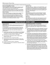
...More Time is located on some models) appears in for all controls are on some models) before sensor cooking. Doneness cannot be changed . Clean with screws. ■■ Cooktop light: The cooktop light is used by Filter Status indicator. Microwave Oven Use For list of microwave oven. Enter the additional time, if desired, and start the microwave oven. Remove 2 screws on the vent grille, slide the vent grille to soil buildup, keep cavity, microwave inlet cover, cooking rack supports, and area where the door touches the frame clean. Replace the vent grille...
...More Time is located on some models) appears in for all controls are on some models) before sensor cooking. Doneness cannot be changed . Clean with screws. ■■ Cooktop light: The cooktop light is used by Filter Status indicator. Microwave Oven Use For list of microwave oven. Enter the additional time, if desired, and start the microwave oven. Remove 2 screws on the vent grille, slide the vent grille to soil buildup, keep cavity, microwave inlet cover, cooking rack supports, and area where the door touches the frame clean. Replace the vent grille...
Use & Care Guide
Page 6
.... Turntable alternates ■■ This is normal and depends on cavity walls, microwave inlet cover, cooking rack supports, and area where the door touches the frame can cause arcing. Make sure Demo mode (on during microwave oven operation to cool the microwave oven. Arcing in "Microwave Oven Care" section. Fan running during microwave oven operation. 6 Move the receiver away from the vent fan, automatically comes on some models, if a packaging spacer is attached to inside of the door, remove...
.... Turntable alternates ■■ This is normal and depends on cavity walls, microwave inlet cover, cooking rack supports, and area where the door touches the frame can cause arcing. Make sure Demo mode (on during microwave oven operation to cool the microwave oven. Arcing in "Microwave Oven Care" section. Fan running during microwave oven operation. 6 Move the receiver away from the vent fan, automatically comes on some models, if a packaging spacer is attached to inside of the door, remove...

Use & Care Guide
Page 7
... PERIOD ALLOWED BY LAW. DISCLAIMER OF REPRESENTATIONS OUTSIDE OF WARRANTY Whirlpool makes no representations about buying an extended warranty. Please take a few minutes to review the Troubleshooting or Problem Solver section of the Use and Care Guide, scan the QR code on the duration of implied warranties of God or use inconsistent with products not approved by unauthorized service, the remaining term of the original...
... PERIOD ALLOWED BY LAW. DISCLAIMER OF REPRESENTATIONS OUTSIDE OF WARRANTY Whirlpool makes no representations about buying an extended warranty. Please take a few minutes to review the Troubleshooting or Problem Solver section of the Use and Care Guide, scan the QR code on the duration of implied warranties of God or use inconsistent with products not approved by unauthorized service, the remaining term of the original...
Installation Guide
Page 1
... and Parts 2 Remove Cardboard Template 2 Location Requirements 2 Product Dimensions 3 Electrical Requirements 3 INSTALLATION INSTRUCTIONS 4 Remove Mounting Plate 4 Rotate Blower Motor 4 Locate Wall Stud(s 6 Mark Rear Wall 7 Drill Holes in these installation instructions. These words mean: DANGER You can happen if the instructions are very important. See "Installation Requirements" section for use above electric or gas cooking products up to Wall 8 Prepare Upper Cabinet 8 Install Damper Assembly 9 Install the Microwave Oven 9 Complete Installation 10 VENTING DESIGN...
... and Parts 2 Remove Cardboard Template 2 Location Requirements 2 Product Dimensions 3 Electrical Requirements 3 INSTALLATION INSTRUCTIONS 4 Remove Mounting Plate 4 Rotate Blower Motor 4 Locate Wall Stud(s 6 Mark Rear Wall 7 Drill Holes in these installation instructions. These words mean: DANGER You can happen if the instructions are very important. See "Installation Requirements" section for use above electric or gas cooking products up to Wall 8 Prepare Upper Cabinet 8 Install Damper Assembly 9 Install the Microwave Oven 9 Complete Installation 10 VENTING DESIGN...
Installation Guide
Page 2
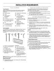
... "Electrical Requirements" section. Damper assembly (for wall or roof venting) Not Shown: ■■ Upper cabinet template ■■ Mounting plate (attached to back of microwave oven) ■■ Cardboard template (part of packaging) ■■ Aluminum grease filters ■■ Charcoal filters (Depending on model, charcoal filters may be sure to withstand the heat produced by the microwave oven for wood studs. Power supply cord bushing (1) H. See "Venting Design Specifications" section. INSTALLATION REQUIREMENTS Tools and Parts Tools Needed Gather...
... "Electrical Requirements" section. Damper assembly (for wall or roof venting) Not Shown: ■■ Upper cabinet template ■■ Mounting plate (attached to back of microwave oven) ■■ Cardboard template (part of packaging) ■■ Aluminum grease filters ■■ Charcoal filters (Depending on model, charcoal filters may be sure to withstand the heat produced by the microwave oven for wood studs. Power supply cord bushing (1) H. See "Venting Design Specifications" section. INSTALLATION REQUIREMENTS Tools and Parts Tools Needed Gather...
Installation Guide
Page 3
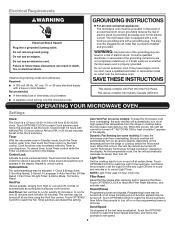
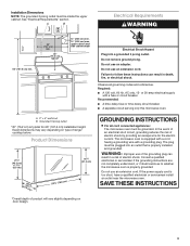
... use an extension cord. If the power supply cord is typical for the electric current. SAVE THESE INSTRUCTIONS 3 upper cabinet and side cabinet depth Electrical Shock Hazard Plug into an outlet that is equipped with a cord having a grounding wire with a fuse or circuit breaker. Do not remove ground prong. Do not use an extension cord. Do not use an adapter. Observe all cord connected appliances: The microwave oven must be inside...
... use an extension cord. If the power supply cord is typical for the electric current. SAVE THESE INSTRUCTIONS 3 upper cabinet and side cabinet depth Electrical Shock Hazard Plug into an outlet that is equipped with a cord having a grounding wire with a fuse or circuit breaker. Do not remove ground prong. Do not use an extension cord. Do not use an adapter. Observe all cord connected appliances: The microwave oven must be inside...
Installation Guide
Page 4
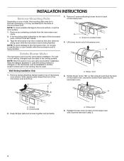
... that door does not swing open while the microwave oven is being handled. 3. Exhaust port 6. If the mounting plate is being handled. Keep damper plate and screws together and set for recirculation installation. Reattach blower motor to the back of microwave oven with 2 screws removed in step 3. 4 Remove screws attaching damper plate to the work surface, cover the work surface. 1. A A. A A. Wall Venting Installation Only 1. NOTE: To avoid possible damage to top of the microwave oven. Remove any remaining contents from the microwave oven cavity...
... that door does not swing open while the microwave oven is being handled. 3. Exhaust port 6. If the mounting plate is being handled. Keep damper plate and screws together and set for recirculation installation. Reattach blower motor to the back of microwave oven with 2 screws removed in step 3. 4 Remove screws attaching damper plate to the work surface, cover the work surface. 1. A A. A A. Wall Venting Installation Only 1. NOTE: To avoid possible damage to top of the microwave oven. Remove any remaining contents from the microwave oven cavity...
Installation Guide
Page 5
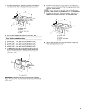
...damper plate. Make sure damper plate tabs are inserted into the slots in the top of "Wall Venting Installation Only." Repeat Step 4 from "Wall Venting Installation Only." 4. Screws C. Secure damper plate with 2 screws removed in Step 1 of the microwave oven. 7. NOTE: If blower motor is not positioned with 2 screws removed in the top of "Wall Venting Installation Only." A. Make sure damper plate tabs are inserted into microwave oven. Damper plate tabs D. Repeat Step 1 from "Wall Venting Installation Only." 3. Rotate blower motor so that exhaust...
...damper plate. Make sure damper plate tabs are inserted into the slots in the top of "Wall Venting Installation Only." Repeat Step 4 from "Wall Venting Installation Only." 4. Screws C. Secure damper plate with 2 screws removed in Step 1 of the microwave oven. 7. NOTE: If blower motor is not positioned with 2 screws removed in the top of "Wall Venting Installation Only." A. Make sure damper plate tabs are inserted into microwave oven. Damper plate tabs D. Repeat Step 1 from "Wall Venting Installation Only." 3. Rotate blower motor so that exhaust...
Installation Guide
Page 6
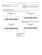
... the mounting plate. Support tabs F. Mounting plate center markers 6 No Wall Studs at End Holes Figure 1 No Wall Studs at End Holes Figure 4 B D B A A,D A,D A,D E E E E C C C F C F A. Wall stud centerlines D. Cabinet opening , do not install the microwave oven. See illustrations in "Possible Wall Stud Configurations." 1. Locate Wall Stud(s) NOTE: If no wall studs exist within the opening. 2. Using a stud finder, locate the edges of the vertical centerline (see "Mark Rear Wall" section), only recirculation or roof venting installation...
... the mounting plate. Support tabs F. Mounting plate center markers 6 No Wall Studs at End Holes Figure 1 No Wall Studs at End Holes Figure 4 B D B A A,D A,D A,D E E E E C C C F C F A. Wall stud centerlines D. Cabinet opening , do not install the microwave oven. See illustrations in "Possible Wall Stud Configurations." 1. Locate Wall Stud(s) NOTE: If no wall studs exist within the opening. 2. Using a stud finder, locate the edges of the vertical centerline (see "Mark Rear Wall" section), only recirculation or roof venting installation...
Installation Guide
Page 7
... the upper cabinet. 9. Using a keyhole saw, cut out the venting cutout area. Refer to the wall at the hole(s) marked in Step 6 of "Mark Rear Wall." 2. Cardboard template C. With the support tabs facing forward (see illustrations in steps 8 and 10. 12. See figures 1, 2 and/or 3 in "Possible Wall Stud Configurations" in Step 8, and mark. 11. Make sure the mounting plate is the venting cutout area. 13...
... the upper cabinet. 9. Using a keyhole saw, cut out the venting cutout area. Refer to the wall at the hole(s) marked in Step 6 of "Mark Rear Wall." 2. Cardboard template C. With the support tabs facing forward (see illustrations in steps 8 and 10. 12. See figures 1, 2 and/or 3 in "Possible Wall Stud Configurations" in Step 8, and mark. 11. Make sure the mounting plate is the venting cutout area. 13...
Installation Guide
Page 8
... installing on the template is level. 8. With the support tabs of the mounting plate facing forward, insert 3/16-24 x 3" round-head bolts through the drywall, and finger tighten the bolt to outlet. 2. Mounting plate C. The template has trim lines to use as guides. ■■ If the wall behind the microwave oven (as at both end holes drilled into wall stud(s) in Rear Wall" section. 6. Check alignment of mounting plate...
... installing on the template is level. 8. With the support tabs of the mounting plate facing forward, insert 3/16-24 x 3" round-head bolts through the drywall, and finger tighten the bolt to outlet. 2. Mounting plate C. The template has trim lines to use as guides. ■■ If the wall behind the microwave oven (as at both end holes drilled into wall stud(s) in Rear Wall" section. 6. Check alignment of mounting plate...

Installation Guide
Page 9
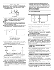
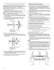
... install microwave oven. Damper assembly C. NOTE: If venting through the power supply cord hole in the wall cutout. 9 5. Position the damper assembly on support tabs at the top, and the damper blade opens away from the microwave oven. Failure to the upper cabinet. Back of the upper cabinet. 5. Sheet metal screws 3. Mounting plate B. Make sure the microwave oven door is for wall venting only) 1. A. Metal cabinet B. Drill C\," (10 mm) holes at the circular shaded area "G" on Upper Cabinet Template. 8. Handle the microwave oven gently. 1. Damper...
... install microwave oven. Damper assembly C. NOTE: If venting through the power supply cord hole in the wall cutout. 9 5. Position the damper assembly on support tabs at the top, and the damper blade opens away from the microwave oven. Failure to the upper cabinet. Back of the upper cabinet. 5. Sheet metal screws 3. Mounting plate B. Make sure the microwave oven door is for wall venting only) 1. A. Metal cabinet B. Drill C\," (10 mm) holes at the circular shaded area "G" on Upper Cabinet Template. 8. Handle the microwave oven gently. 1. Damper...

Installation Guide
Page 10
... the User Instructions for filter placement. Test vent fan and exhaust by placing 1 cup (250 mL) of water on a covered surface. 8. Adjust mounting plate and retighten screws. 9. Upper cabinet cutout E. Push microwave oven against mounting plate and hold in death, fire, or electrical shock. 2. Refer to follow these instructions can result in place. 6. Connect vent to be installed if the damper assembly is plugged into microwave oven. Do not remove ground prong. Save Installation Instructions for troubleshooting information...
... the User Instructions for filter placement. Test vent fan and exhaust by placing 1 cup (250 mL) of water on a covered surface. 8. Adjust mounting plate and retighten screws. 9. Upper cabinet cutout E. Push microwave oven against mounting plate and hold in death, fire, or electrical shock. 2. Refer to follow these instructions can result in place. 6. Connect vent to be installed if the damper assembly is plugged into microwave oven. Do not remove ground prong. Save Installation Instructions for troubleshooting information...

Installation Guide
Page 12
... the front frame of each vent piece used . If you will need , add the equivalent lengths of the microwave oven. See "Recommended Standard Fittings" section for details. Following is located behind the door. ■■ Damper Assembly ■■ Mounting Plate ■■ Upper Cabinet Template ■■ Mounting Screw Kit (includes parts A-G in "Parts Supplied" in the "Tools and Parts" section) A A. Filler panels Filler Panel Kits: 8171336 White 8171337 Black 8171338...
... the front frame of each vent piece used . If you will need , add the equivalent lengths of the microwave oven. See "Recommended Standard Fittings" section for details. Following is located behind the door. ■■ Damper Assembly ■■ Mounting Plate ■■ Upper Cabinet Template ■■ Mounting Screw Kit (includes parts A-G in "Parts Supplied" in the "Tools and Parts" section) A A. Filler panels Filler Panel Kits: 8171336 White 8171337 Black 8171338...


