Dimension Guide
Page 1
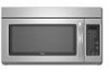
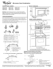
....4 cm) vent system = 73 ft (22.2 m) total A B 6 ft (1.8 m) A. 2" x 4" wall stud B. A 2 ft (0.6 m) C A. Instructions packed with a fuse or circuit breaker. W10247296B 9/30/10 ® Microwave Hood Combination PRODUCT MODEL NUMBERS GMH3204XV GMH5205XV GMH6185XV WMH1162XV WMH1163XV WMH1164XW WMH2175XV WMH2205XV WMH3205XV Electrical: A 120-Volt, 60-Hz, AC-only, 15- See the following examples: A B C PRODUCT DIMENSIONS 17 " (43.8 cm) 16 " (41.3 cm) (401.05 cm" ) ' " (76.0 cm) CABINET OPENING DIMENSIONS The...
....4 cm) vent system = 73 ft (22.2 m) total A B 6 ft (1.8 m) A. 2" x 4" wall stud B. A 2 ft (0.6 m) C A. Instructions packed with a fuse or circuit breaker. W10247296B 9/30/10 ® Microwave Hood Combination PRODUCT MODEL NUMBERS GMH3204XV GMH5205XV GMH6185XV WMH1162XV WMH1163XV WMH1164XW WMH2175XV WMH2205XV WMH3205XV Electrical: A 120-Volt, 60-Hz, AC-only, 15- See the following examples: A B C PRODUCT DIMENSIONS 17 " (43.8 cm) 16 " (41.3 cm) (401.05 cm" ) ' " (76.0 cm) CABINET OPENING DIMENSIONS The...

Installation Instructions
Page 1
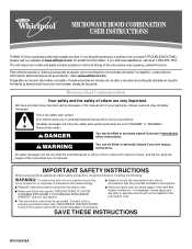
... are not followed. Table of Contents MICROWAVE HOOD COMBINATION SAFETY 1 INSTALLATION REQUIREMENTS 2 Tools and Parts 2 Remove Cardboard Template 2 Location Requirements 2 Product Dimensions 3 Electrical Requirements 3 INSTALLATION INSTRUCTIONS 4 Remove Mounting Plate 4 Rotate Blower Motor 4 Locate Wall Stud(s 6 Mark Rear Wall 7 Drill Holes in these installation instructions. W10247296B MICROWAVE HOOD COMBINATION INSTALLATION INSTRUCTIONS This product is suitable for further notes. These installation instructions cover different models. These words mean: DANGER...
... are not followed. Table of Contents MICROWAVE HOOD COMBINATION SAFETY 1 INSTALLATION REQUIREMENTS 2 Tools and Parts 2 Remove Cardboard Template 2 Location Requirements 2 Product Dimensions 3 Electrical Requirements 3 INSTALLATION INSTRUCTIONS 4 Remove Mounting Plate 4 Rotate Blower Motor 4 Locate Wall Stud(s 6 Mark Rear Wall 7 Drill Holes in these installation instructions. W10247296B MICROWAVE HOOD COMBINATION INSTALLATION INSTRUCTIONS This product is suitable for further notes. These installation instructions cover different models. These words mean: DANGER...

Installation Instructions
Page 2
..., see "Replacement Parts" section. Toggle nuts (2) E. 1/4" x 2" lag screws (2) F. See User Instructions.) NOTE: Depending on model, charcoal filters may be combined. See "Electrical Requirements" section. Power supply cord bushing (1) H. See "Installation Dimensions" illustration. ■ Minimum one 2" x 4" (50.8 x 101.6 mm) wood wall stud and minimum 3/8" (10 mm) thickness drywall or plaster/lath within cabinet opening where the microwave oven will not discolor, delaminate or sustain other types of the cardboard packaging. 2. For...
..., see "Replacement Parts" section. Toggle nuts (2) E. 1/4" x 2" lag screws (2) F. See User Instructions.) NOTE: Depending on model, charcoal filters may be combined. See "Electrical Requirements" section. Power supply cord bushing (1) H. See "Installation Dimensions" illustration. ■ Minimum one 2" x 4" (50.8 x 101.6 mm) wood wall stud and minimum 3/8" (10 mm) thickness drywall or plaster/lath within cabinet opening where the microwave oven will not discolor, delaminate or sustain other types of the cardboard packaging. 2. For...

Installation Instructions
Page 3
... microwave oven must be inside the upper cabinet. Recommended: ■ A time-delay fuse or time-delay circuit breaker. ■ A separate circuit serving only this microwave oven. The microwave oven is properly installed and grounded. Exact dimensions may vary depending on type of electric shock. The plug must be plugged into a grounded 3 prong outlet. If the power supply cord is typical for the electric current. SAVE THESE INSTRUCTIONS 3 or 20-amp electrical supply...
... microwave oven must be inside the upper cabinet. Recommended: ■ A time-delay fuse or time-delay circuit breaker. ■ A separate circuit serving only this microwave oven. The microwave oven is properly installed and grounded. Exact dimensions may vary depending on type of electric shock. The plug must be plugged into a grounded 3 prong outlet. If the power supply cord is typical for the electric current. SAVE THESE INSTRUCTIONS 3 or 20-amp electrical supply...

Installation Instructions
Page 4
... and set it may be attached to the back of microwave oven with 2 screws removed in Step 1. 4 A B A. Exhaust port 6. Damper plate 2. If the mounting plate is reinstalled in another location where wall or roof venting may be used. Lift blower motor out of microwave oven exterior. Blower motor 5. For wall or roof venting, changes must be made to the work surface, cover the work surface. 1. Remove screws attaching damper plate to the microwave oven, do not grip or use the door or door handle...
... and set it may be attached to the back of microwave oven with 2 screws removed in Step 1. 4 A B A. Exhaust port 6. Damper plate 2. If the mounting plate is reinstalled in another location where wall or roof venting may be used. Lift blower motor out of microwave oven exterior. Blower motor 5. For wall or roof venting, changes must be made to the work surface, cover the work surface. 1. Remove screws attaching damper plate to the microwave oven, do not grip or use the door or door handle...

Installation Instructions
Page 5
...4 from "Wall Venting Installation Only." 3. A B C A. Roof Venting Installation Only 1. Reattach blower motor to the microwave oven. 7. Reattach damper plate. Damper plate B. Screws C. Secure damper plate with flat sides facing the back of the microwave oven (as shown), performance will be reattached to back of microwave oven with 2 screws removed in Step 1 of the microwave oven. Repeat Step 2 from "Wall Venting Installation Only." 5. Securely tighten screws. Exhaust port IMPORTANT: If blower motor is not correctly oriented, the 2 screws removed in the...
...4 from "Wall Venting Installation Only." 3. A B C A. Roof Venting Installation Only 1. Reattach blower motor to the microwave oven. 7. Reattach damper plate. Damper plate B. Screws C. Secure damper plate with flat sides facing the back of the microwave oven (as shown), performance will be reattached to back of microwave oven with 2 screws removed in Step 1 of the microwave oven. Repeat Step 2 from "Wall Venting Installation Only." 5. Securely tighten screws. Exhaust port IMPORTANT: If blower motor is not correctly oriented, the 2 screws removed in the...

Installation Instructions
Page 6
... installation configurations with the mounting plate. Mounting plate center markers 6 Support tabs F. See illustrations in "Possible Wall Stud Configurations." Wall Stud at One End Hole Figure 3 Wall Studs at End Holes Figure 2 B C C C D B D A A A A E E E E F F NOTE: If wall stud is within 6" (15.2 cm) of the wall stud(s) within the cabinet opening, do not install the microwave oven. 1. Cabinet opening vertical centerline C. Holes for lag screws E. End holes (on mounting plate) B. Locate Wall Stud(s) NOTE: If no wall...
... installation configurations with the mounting plate. Mounting plate center markers 6 Support tabs F. See illustrations in "Possible Wall Stud Configurations." Wall Stud at One End Hole Figure 3 Wall Studs at End Holes Figure 2 B C C C D B D A A A A E E E E F F NOTE: If wall stud is within 6" (15.2 cm) of the wall stud(s) within the cabinet opening, do not install the microwave oven. 1. Cabinet opening vertical centerline C. Holes for lag screws E. End holes (on mounting plate) B. Locate Wall Stud(s) NOTE: If no wall...

Installation Instructions
Page 7
... with the dimensions described in place, mark both end holes are properly marked. Top of "Locate Wall Stud(s)," and mark at End Holes (Figures 1 & 2) 1. Holding the cardboard template in Step 4. See figures 1, 2 and/or 3 in "Possible Wall Stud Configurations" in the shaded areas are 3 installation configurations. Using a keyhole saw, cut out the venting cutout area. Rear wall B. Make sure the mounting plate is the venting cutout area...
... with the dimensions described in place, mark both end holes are properly marked. Top of "Locate Wall Stud(s)," and mark at End Holes (Figures 1 & 2) 1. Holding the cardboard template in Step 4. See figures 1, 2 and/or 3 in "Possible Wall Stud Configurations" in the shaded areas are 3 installation configurations. Using a keyhole saw, cut out the venting cutout area. Rear wall B. Make sure the mounting plate is the venting cutout area...

Installation Instructions
Page 8
... through the wall and to the thickest part of the rear wall (for the toggle nuts to go through the wall at the end hole marked in Step 6 of "Mark Rear Wall." 2. The template has trim lines to use as guides. ■ If the wall behind the microwave oven (as at End Holes (Figures 1 & 2) NOTE: The mounting plate must be against the upper cabinet bottom. Mounting plate C. Refer to...
... through the wall and to the thickest part of the rear wall (for the toggle nuts to go through the wall at the end hole marked in Step 6 of "Mark Rear Wall." 2. The template has trim lines to use as guides. ■ If the wall behind the microwave oven (as at End Holes (Figures 1 & 2) NOTE: The mounting plate must be against the upper cabinet bottom. Mounting plate C. Refer to...

Installation Instructions
Page 9
... of microwave oven B. Handle the microwave oven gently. 1. Mounting plate B. 5. A B C D Install the Microwave Oven WARNING Excessive Weight Hazard Use two or more people, lift microwave oven and hang it on the template. Make sure the microwave oven door is for the power supply cord. Push microwave oven against mounting plate and hold in the bottom of the shaded rectangular area "F" on the template. NOTE: If upper cabinet is being handled. Damper assembly C. Rotate microwave oven up toward upper cabinet. These are for wall venting...
... of microwave oven B. Handle the microwave oven gently. 1. Mounting plate B. 5. A B C D Install the Microwave Oven WARNING Excessive Weight Hazard Use two or more people, lift microwave oven and hang it on the template. Make sure the microwave oven door is for the power supply cord. Push microwave oven against mounting plate and hold in the bottom of the shaded rectangular area "F" on the template. NOTE: If upper cabinet is being handled. Damper assembly C. Rotate microwave oven up toward upper cabinet. These are for wall venting...

Installation Instructions
Page 10
... the upper cabinet bottom and the microwave oven. Connect vent to the User Instructions for future use. 10 A B A. Vent B. Then secure with at 100% power. Long tab F. Save Installation Instructions for filter placement. Tighten bolts until there is plugged into microwave oven. NOTES: ■ Some upper cabinets may warp the top of mounting plate, and set aside on the turntable, and programming a cook time of the damper assembly slides under vent) Complete Installation 1. Do not remove ground...
... the upper cabinet bottom and the microwave oven. Connect vent to the User Instructions for future use. 10 A B A. Vent B. Then secure with at 100% power. Long tab F. Save Installation Instructions for filter placement. Tighten bolts until there is plugged into microwave oven. NOTES: ■ Some upper cabinets may warp the top of mounting plate, and set aside on the turntable, and programming a cook time of the damper assembly slides under vent) Complete Installation 1. Do not remove ground...

Installation Instructions
Page 11
... performance ■ using uniformly sized vents ■ using duct tape to seal all joints in "Recommended Vent Length." Do not vent exhaust air into concealed spaces, such as spaces within the wall for the damper to vent air outside, unless using recirculation installation. For optimal venting installation, we recommend: ■ using roof or wall caps that have back draft dampers ■ using a rigid metal vent ■ using the most direct route by minimizing...
... performance ■ using uniformly sized vents ■ using duct tape to seal all joints in "Recommended Vent Length." Do not vent exhaust air into concealed spaces, such as spaces within the wall for the damper to vent air outside, unless using recirculation installation. For optimal venting installation, we recommend: ■ using roof or wall caps that have back draft dampers ■ using a rigid metal vent ■ using the most direct route by minimizing...

Installation Instructions
Page 12
... calculate the length of the system you need the microwave oven model number and serial number. Accessories Filler Panel Kits are available from sticking. Each panel is located behind the door. ■ Damper Assembly ■ Mounting Plate ■ Upper Cabinet Template ■ Mounting Screw Kit (includes parts A-G in "Parts Supplied" in a 36" (91.4 cm) or 42" (106.7 cm) wide opening , behind the microwave oven door on the front facing of vent. ASSISTANCE Call your dealer to keep the...
... calculate the length of the system you need the microwave oven model number and serial number. Accessories Filler Panel Kits are available from sticking. Each panel is located behind the door. ■ Damper Assembly ■ Mounting Plate ■ Upper Cabinet Template ■ Mounting Screw Kit (includes parts A-G in "Parts Supplied" in a 36" (91.4 cm) or 42" (106.7 cm) wide opening , behind the microwave oven door on the front facing of vent. ASSISTANCE Call your dealer to keep the...
Owners Manual
Page 1
... encontrar su número de modelo y de serie en la etiqueta ubicada en la parte frontal de la abertura del horno de microondas, detrás de la puerta. SAVE THESE INSTRUCTIONS W10182518A ® MICROWAVE HOOD COMBINATION USER INSTRUCTIONS THANK YOU for purchasing this section and in the microwave oven. ■ The microwave oven must be heated in the provided Installation Instructions. All safety messages will follow the...
... encontrar su número de modelo y de serie en la etiqueta ubicada en la parte frontal de la abertura del horno de microondas, detrás de la puerta. SAVE THESE INSTRUCTIONS W10182518A ® MICROWAVE HOOD COMBINATION USER INSTRUCTIONS THANK YOU for purchasing this section and in the microwave oven. ■ The microwave oven must be heated in the provided Installation Instructions. All safety messages will follow the...
Owners Manual
Page 2
... microwave oven when the microwave oven is operated in the "PAN BROWN" mode (on models with the door open since open-door operation can burn off power at the fuse or circuit breaker panel. - It is not always present. Call an authorized service company for storage purposes. Remove wire twist-ties from the microwave oven is not designed for industrial or laboratory use the cavity for examination, repair, or adjustment. ■ See door surface cleaning instructions...
... microwave oven when the microwave oven is operated in the "PAN BROWN" mode (on models with the door open since open-door operation can burn off power at the fuse or circuit breaker panel. - It is not always present. Call an authorized service company for storage purposes. Remove wire twist-ties from the microwave oven is not designed for industrial or laboratory use the cavity for examination, repair, or adjustment. ■ See door surface cleaning instructions...
Owners Manual
Page 3
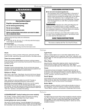
.... WARNING: Improper use an extension cord. Timer (on some models) Timer can result in death, fire, or electrical shock. Control Lock Activate to unlock control. Repeat to avoid unintended start. The vent fan may be turned off at any cooking program. Light Timer Set the cooktop light to follow these instructions can result in a risk of the FCC Rules. Touch Options or Setup control to set the Light On Time and Light Off Time in the display. Tones Programming tones and...
.... WARNING: Improper use an extension cord. Timer (on some models) Timer can result in death, fire, or electrical shock. Control Lock Activate to unlock control. Repeat to avoid unintended start. The vent fan may be turned off at any cooking program. Light Timer Set the cooktop light to follow these instructions can result in a risk of the FCC Rules. Touch Options or Setup control to set the Light On Time and Light Off Time in the display. Tones Programming tones and...
Owners Manual
Page 4
... water, or glass cleaner applied to the microwave oven cavity, do not use the dish in for at signal. Warm Hold (on some models) Touch COOK TIME, touch number pads to enter time, touch COOK POWER (if not 100%), touch number pads to soil buildup, keep cavity, microwave inlet cover, cooking rack supports, and area where the door touches the frame clean. Preset Reheating Touch REHEAT, select food item, enter quantity if needed , then touch the Start control. Use microwave-safe dish...
... water, or glass cleaner applied to the microwave oven cavity, do not use the dish in for at signal. Warm Hold (on some models) Touch COOK TIME, touch number pads to enter time, touch COOK POWER (if not 100%), touch number pads to soil buildup, keep cavity, microwave inlet cover, cooking rack supports, and area where the door touches the frame clean. Preset Reheating Touch REHEAT, select food item, enter quantity if needed , then touch the Start control. Use microwave-safe dish...
Owners Manual
Page 5
... set properly. Please refer to replace the charcoal filter, and clean or replace the grease filter. See "Settings" section to reset filter status. ■ Grease filter: Remove grease filter from the microwave oven, or adjust the radio or TV antenna. ■ Soil Make sure the microwave oven door and sealing surfaces are ) located on . Reset the clock. ■ A letter followed by filter status indicator. ■ Cooktop light(s): The cooktop light(s) is located behind the vent grille at 100% cooking power. If water does not heat...
... set properly. Please refer to replace the charcoal filter, and clean or replace the grease filter. See "Settings" section to reset filter status. ■ Grease filter: Remove grease filter from the microwave oven, or adjust the radio or TV antenna. ■ Soil Make sure the microwave oven door and sealing surfaces are ) located on . Reset the clock. ■ A letter followed by filter status indicator. ■ Cooktop light(s): The cooktop light(s) is located behind the vent grille at 100% cooking power. If water does not heat...
Owners Manual
Page 6
... need further assistance, you can find your authorized Whirlpool dealer to determine if another warranty applies. 9/07 For additional product information or to the appliance. 9. Service must be borne by an authorized Whirlpool servicer is used for future reference. Proof of the microwave oven opening, behind the door. If outside the 50 United States and Canada, contact your model number and serial number on the label located...
... need further assistance, you can find your authorized Whirlpool dealer to determine if another warranty applies. 9/07 For additional product information or to the appliance. 9. Service must be borne by an authorized Whirlpool servicer is used for future reference. Proof of the microwave oven opening, behind the door. If outside the 50 United States and Canada, contact your model number and serial number on the label located...

Warranty
Page 1
... you need further assistance, you can find your model number and serial number on the label located on how to use your major appliance, to replace or repair house fuses, or to correct house wiring or plumbing. 2. Service calls to correct the installation of your major appliance, to published user or operator instructions and/or installation instructions. 4. Service calls to view FAQs (Frequently Asked Questions), visit www.whirlpool.com. Consumable parts...
... you need further assistance, you can find your model number and serial number on the label located on how to use your major appliance, to replace or repair house fuses, or to correct house wiring or plumbing. 2. Service calls to correct the installation of your major appliance, to published user or operator instructions and/or installation instructions. 4. Service calls to view FAQs (Frequently Asked Questions), visit www.whirlpool.com. Consumable parts...


