Dimension Guide
Page 1
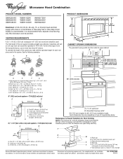
... Wall cap F E. 3 " x 10" to 6" (8.3 x 25.4 cm to 15.2 cm) rectangular to 15.2 cm = 1.5 m) B. Vent extension piece, at least 3" (7.6 cm) high Because Whirlpool Corporation policy includes a continuous commitment to round transition piece = 5 ft (1.5 m) D. 2 ft (0.6 m) + 6 ft (1.8 m) straight = 8 ft... = 8 ft (2.4 m) B C 3" (7.6 cm) D A. ® Microwave Hood Combination PRODUCT MODEL NUMBERS GMH3204XV GMH5205XV GMH6185XV WMH1162XV WMH1163XV WMH1164XW WMH2175XV WMH2205XV WMH3205XV Electrical: A 120-Volt, 60-Hz, AC-only, 15- For best performance, use no more than three 90° ...
... Wall cap F E. 3 " x 10" to 6" (8.3 x 25.4 cm to 15.2 cm) rectangular to 15.2 cm = 1.5 m) B. Vent extension piece, at least 3" (7.6 cm) high Because Whirlpool Corporation policy includes a continuous commitment to round transition piece = 5 ft (1.5 m) D. 2 ft (0.6 m) + 6 ft (1.8 m) straight = 8 ft... = 8 ft (2.4 m) B C 3" (7.6 cm) D A. ® Microwave Hood Combination PRODUCT MODEL NUMBERS GMH3204XV GMH5205XV GMH6185XV WMH1162XV WMH1163XV WMH1164XW WMH2175XV WMH2205XV WMH3205XV Electrical: A 120-Volt, 60-Hz, AC-only, 15- For best performance, use no more than three 90° ...

Installation Instructions
Page 1
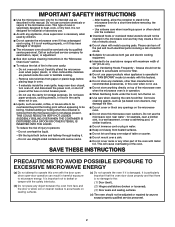
... tell you what the potential hazard is, tell you how to Wall 8 Prepare Upper Cabinet 8 Install Damper Assembly 9 Install the Microwave Oven 9 Complete Installation 10 VENTING DESIGN SPECIFICATIONS 11 ASSISTANCE 12 Replacement Parts 12 Accessories 12 MICROWAVE HOOD COMBINATION SAFETY Your safety and the safety of injury, and tell you what...
... tell you what the potential hazard is, tell you how to Wall 8 Prepare Upper Cabinet 8 Install Damper Assembly 9 Install the Microwave Oven 9 Complete Installation 10 VENTING DESIGN SPECIFICATIONS 11 ASSISTANCE 12 Replacement Parts 12 Accessories 12 MICROWAVE HOOD COMBINATION SAFETY Your safety and the safety of injury, and tell you what...

Installation Instructions
Page 2
... here are using a rectangular to round transition piece, the 3" (7.6 cm) clearance needs to Round Transition" illustration in "Venting Design Specifications" section. 2 Power supply cord bushing (1) H. Check with any obstructions so that the damper blade can open freely and fully. ...within cabinet opening where the microwave oven will not discolor, delaminate or sustain other types of the cardboard packaging. 2. For Roof Venting Installation Only: ■ If you are for cooking. INSTALLATION REQUIREMENTS Tools and Parts Tools Needed Gather the required tools and parts...
... here are using a rectangular to round transition piece, the 3" (7.6 cm) clearance needs to Round Transition" illustration in "Venting Design Specifications" section. 2 Power supply cord bushing (1) H. Check with any obstructions so that the damper blade can open freely and fully. ...within cabinet opening where the microwave oven will not discolor, delaminate or sustain other types of the cardboard packaging. 2. For Roof Venting Installation Only: ■ If you are for cooking. INSTALLATION REQUIREMENTS Tools and Parts Tools Needed Gather the required tools and parts...

Installation Instructions
Page 4
... any remaining contents from the microwave oven cavity. 2. Rotate Blower Motor The microwave oven is reinstalled in Step 3. 7. For wall or roof venting, changes must be attached to the work surface, cover the work surface. 1. Damper plate tabs D. If the mounting plate is attached to the... back of the microwave oven. Remove 2 screws attaching blower motor to the venting system. A A. NOTE: To avoid possible damage to the back of the microwave oven, remove it may be made to back of microwave oven ...
... any remaining contents from the microwave oven cavity. 2. Rotate Blower Motor The microwave oven is reinstalled in Step 3. 7. For wall or roof venting, changes must be attached to the work surface, cover the work surface. 1. Damper plate tabs D. If the mounting plate is attached to the... back of the microwave oven. Remove 2 screws attaching blower motor to the venting system. A A. NOTE: To avoid possible damage to the back of the microwave oven, remove it may be made to back of microwave oven ...

Installation Instructions
Page 5
... be reattached to the microwave oven. 7. Slots 8. Repeat Step 4 from "Wall Venting Installation Only." 3. A B C A. Screws C. Lower blower motor back into the slots in Step 1 of "Wall Venting Installation Only." Exhaust port IMPORTANT: If blower motor is not correctly oriented, the 2...cannot be poor. Securely tighten screws. D A. Repeat Step 1 from "Wall Venting Installation Only." 4. Make sure damper plate tabs are inserted into microwave oven. Damper plate B. Roof Venting Installation Only 1. Reattach damper plate. Rotate blower motor so that exhaust ports face...
... be reattached to the microwave oven. 7. Slots 8. Repeat Step 4 from "Wall Venting Installation Only." 3. A B C A. Screws C. Lower blower motor back into the slots in Step 1 of "Wall Venting Installation Only." Exhaust port IMPORTANT: If blower motor is not correctly oriented, the 2...cannot be poor. Securely tighten screws. D A. Repeat Step 1 from "Wall Venting Installation Only." 4. Make sure damper plate tabs are inserted into microwave oven. Damper plate B. Roof Venting Installation Only 1. Reattach damper plate. Rotate blower motor so that exhaust ports face...

Installation Instructions
Page 6
Using a stud finder, locate the edges of the vertical centerline (see "Mark Rear Wall" section), only recirculation or roof venting installation can be done. End holes (on mounting plate) B. Cabinet opening vertical centerline C. Wall stud centerlines D. Holes for lag screws E. Locate Wall Stud(s) NOTE: If ...
Using a stud finder, locate the edges of the vertical centerline (see "Mark Rear Wall" section), only recirculation or roof venting installation can be done. End holes (on mounting plate) B. Cabinet opening vertical centerline C. Wall stud centerlines D. Holes for lag screws E. Locate Wall Stud(s) NOTE: If ...

Installation Instructions
Page 7
...from the centerline. 5. Refer to complete the 12" x 4" (30.5 x 10.2 cm) rectangle. Using a keyhole saw, cut out the venting cutout area. Installation for No Wall Studs at least 1, preferably 2 hole(s) through the wall at both end holes marked in Rear Wall In ..., and must align with toggle nuts; Holding the mounting plate in place, find and clearly mark the vertical centerline of 1 lag screw, preferably 2. 1. Wall Venting Installation Only Upper cabinet bottom ³⁄₈" (1 cm) 4" (10.2 cm) Centerline 6" (15.2 cm) 6" (15.2 cm) 8. Using measuring ...
...from the centerline. 5. Refer to complete the 12" x 4" (30.5 x 10.2 cm) rectangle. Using a keyhole saw, cut out the venting cutout area. Installation for No Wall Studs at least 1, preferably 2 hole(s) through the wall at both end holes marked in Rear Wall In ..., and must align with toggle nuts; Holding the mounting plate in place, find and clearly mark the vertical centerline of 1 lag screw, preferably 2. 1. Wall Venting Installation Only Upper cabinet bottom ³⁄₈" (1 cm) 4" (10.2 cm) Centerline 6" (15.2 cm) 6" (15.2 cm) 8. Using measuring ...

Installation Instructions
Page 9
... Sheet metal screws 3. Cut the 1¹⁄₂" (3.8 cm) diameter hole at points "D" and "E" on the template. These are for wall venting only) 1. Cut 3/4" (19 mm) hole at the bottom of microwave oven B. Position the damper assembly on Upper Cabinet Template. 8. Support tabs ... side of the shaded rectangular area "F" on the back of the upper cabinet. 5. Back of mounting plate. Metal cabinet B. NOTE: If venting through the power supply cord hole in the wall cutout. 6. Power supply cord bushing 6. A B C D Install the Microwave Oven WARNING ...
... Sheet metal screws 3. Cut the 1¹⁄₂" (3.8 cm) diameter hole at points "D" and "E" on the template. These are for wall venting only) 1. Cut 3/4" (19 mm) hole at the bottom of microwave oven B. Position the damper assembly on Upper Cabinet Template. 8. Support tabs ... side of the shaded rectangular area "F" on the back of the upper cabinet. 5. Back of mounting plate. Metal cabinet B. NOTE: If venting through the power supply cord hole in the wall cutout. 6. Power supply cord bushing 6. A B C D Install the Microwave Oven WARNING ...

Installation Instructions
Page 10
...placement. Longer or shorter bolts are available at 100% power. Refer to the User Instructions for future use. 10 Bolts For Roof Venting Installation Only 1. Do not use an adapter. WARNING A. Sheet metal screw D. Plug microwave oven into a grounded 3 prong outlet... supply cord is required, rotate microwave oven downward. Replace the fuse or reset the circuit breaker. Repeat steps 3-6. 10. Connect vent to damper assembly. Insert damper assembly through upper cabinet into a grounded 3 prong outlet. ■ See the User Instructions for ...
...placement. Longer or shorter bolts are available at 100% power. Refer to the User Instructions for future use. 10 Bolts For Roof Venting Installation Only 1. Do not use an adapter. WARNING A. Sheet metal screw D. Plug microwave oven into a grounded 3 prong outlet... supply cord is required, rotate microwave oven downward. Replace the fuse or reset the circuit breaker. Repeat steps 3-6. 10. Connect vent to damper assembly. Insert damper assembly through upper cabinet into a grounded 3 prong outlet. ■ See the User Instructions for ...

Installation Instructions
Page 11
... reference only. Rectangular to round transition piece: 3¹⁄₄" x 10" to 6" = 5 ft (8.3 x 25.4 cm to Round Transition" illustration. A B C Roof venting Roof cap Wall venting Wall cap D E F G A. Roof cap: 3¹⁄₄" x 10" = 24 ft (8.3 x 25.4 cm = 7.3 m) C. 90° elbow: 3¹...Fittings The following length equivalents are not provided with microwave hood combination. ■ We do not recommend using a flexible metal vent. ■ To avoid possible product damage, be sure that the damper can open fully. Wall cap: 3¹⁄&#...
... reference only. Rectangular to round transition piece: 3¹⁄₄" x 10" to 6" = 5 ft (8.3 x 25.4 cm to Round Transition" illustration. A B C Roof venting Roof cap Wall venting Wall cap D E F G A. Roof cap: 3¹⁄₄" x 10" = 24 ft (8.3 x 25.4 cm = 7.3 m) C. 90° elbow: 3¹...Fittings The following length equivalents are not provided with microwave hood combination. ■ We do not recommend using a flexible metal vent. ■ To avoid possible product damage, be sure that the damper can open fully. Wall cap: 3¹⁄&#...

Installation Instructions
Page 12
... x 10" (8.3 x 25.4 cm) 90° elbow = 25 ft (7.6 m) B. 1 wall cap = 40 ft (12.2 m) C. 2 ft (0.6 m) + 6 ft (1.8 m) straight = 8 ft (2.4 m) 6" (15.2 cm) vent system = 73 ft (22.2 m) total A B 6 ft (1.8 m) 2 ft (0.6 m) C D A. Two 90° elbows = 20 ft (6.1 m) B. 1 wall cap = 40 ft (12.2 m) C. 1 rectangular to be replaced, ... for either type of 140 ft (42.7 m) for equivalent lengths. In addition, a rectangular 3" (7.6 cm) extension vent between the damper assembly and rectangular to keep the damper from your authorized dealer or service center for details. W10247296B SP ...
... x 10" (8.3 x 25.4 cm) 90° elbow = 25 ft (7.6 m) B. 1 wall cap = 40 ft (12.2 m) C. 2 ft (0.6 m) + 6 ft (1.8 m) straight = 8 ft (2.4 m) 6" (15.2 cm) vent system = 73 ft (22.2 m) total A B 6 ft (1.8 m) 2 ft (0.6 m) C D A. Two 90° elbows = 20 ft (6.1 m) B. 1 wall cap = 40 ft (12.2 m) C. 1 rectangular to be replaced, ... for either type of 140 ft (42.7 m) for equivalent lengths. In addition, a rectangular 3" (7.6 cm) extension vent between the damper assembly and rectangular to keep the damper from your authorized dealer or service center for details. W10247296B SP ...
Owners Manual
Page 2
... to be allowed to heat, cook, or dry food. Do not use . ■ Do not store anything directly on . ■ Use care when cleaning the vent-hood filter. This type of fire in water. ■ Keep cord away from heated surfaces. ■ Do not let cord hang over edge of table...
... to be allowed to heat, cook, or dry food. Do not use . ■ Do not store anything directly on . ■ Use care when cleaning the vent-hood filter. This type of fire in water. ■ Keep cord away from heated surfaces. ■ Do not let cord hang over edge of table...
Owners Manual
Page 3
... Programming tones and signals. Programming tones may be plugged into a grounded 3 prong outlet. Touch the Options or Setup control to reach the "Vent Fan" submenu, and select the setting. This is properly grounded. Do not remove ground prong. Observe all governing codes and ordinances. The plug... are not completely understood, or if doubt exists as cooling fan during any cooking program. Do not use an extension cord. The vent fan may be adjusted. Filter Reset Reset the filter status after 2-level cooking. Turntable Turntable may be turned off at certain times....
... Programming tones and signals. Programming tones may be plugged into a grounded 3 prong outlet. Touch the Options or Setup control to reach the "Vent Fan" submenu, and select the setting. This is properly grounded. Do not remove ground prong. Observe all governing codes and ordinances. The plug... are not completely understood, or if doubt exists as cooling fan during any cooking program. Do not use an extension cord. The vent fan may be adjusted. Filter Reset Reset the filter status after 2-level cooking. Turntable Turntable may be turned off at certain times....
Owners Manual
Page 4
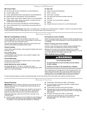
...): To avoid damage to follow label instructions on some models): mild soap and water, then rinse with clean water and dry with plastic wrap and vent. Adjust doneness for 1 lb (454 g). If programming additional stages, enter the cook time and cook power of preset programs, see the Cooking Guide label on...
...): To avoid damage to follow label instructions on some models): mild soap and water, then rinse with clean water and dry with plastic wrap and vent. Adjust doneness for 1 lb (454 g). If programming additional stages, enter the cook time and cook power of preset programs, see the Cooking Guide label on...
Owners Manual
Page 5
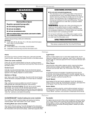
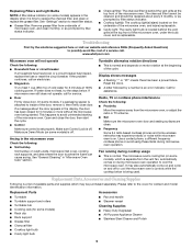
www.whirlpool.com Microwave oven will not operate Check the following : ■ Soil ...call an electrician. ■ Magnetron Try to reset filter status. ■ Grease filter: Remove grease filter from the vent fan, automatically comes on some models), which may be replaced about the door appears in "Microwave Oven Care" section.... Replacement Parts, Accesssories and Cleaning Supplies Following is a list of available parts and supplies which is located behind the vent grille at the top front of the microwave oven. This happens to cool the microwave oven. Display shows messages &#...
www.whirlpool.com Microwave oven will not operate Check the following : ■ Soil ...call an electrician. ■ Magnetron Try to reset filter status. ■ Grease filter: Remove grease filter from the vent fan, automatically comes on some models), which may be replaced about the door appears in "Microwave Oven Care" section.... Replacement Parts, Accesssories and Cleaning Supplies Following is a list of available parts and supplies which is located behind the vent grille at the top front of the microwave oven. This happens to cool the microwave oven. Display shows messages &#...


