Dimension Guide
Page 1
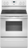
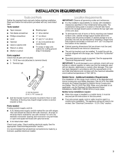
...the model/serial number rating plate. upper cabinet depth B. 30" (76.2 cm) min. opening width C. For complete details, see following Range Rating chart). Ref. q A circuit breaker is located on the left side frame behind storage drawer or right side of frame behind the... be connected to the proper electrical voltage and frequency as a reference for leveling the range is manufactured with leveling legs screwed all the way in the "Level Range" section. E F Because Whirlpool Corporation policy includes a continuous commitment to improve our products, we reserve the right to...
...the model/serial number rating plate. upper cabinet depth B. 30" (76.2 cm) min. opening width C. For complete details, see following Range Rating chart). Ref. q A circuit breaker is located on the left side frame behind storage drawer or right side of frame behind the... be connected to the proper electrical voltage and frequency as a reference for leveling the range is manufactured with leveling legs screwed all the way in the "Level Range" section. E F Because Whirlpool Corporation policy includes a continuous commitment to improve our products, we reserve the right to...
Installation Guide
Page 1
U.S.A. W10403811B INSTALLATION INSTRUCTIONS 30" (76 CM) FREESTANDING ELECTRIC RANGES Table of Contents RANGE SAFETY 2 INSTALLATION REQUIREMENTS 3 Tools and Parts 3 Location Requirements 3 Electrical Requirements - Only 8 Verify Anti-Tip Bracket Is Installed and Engaged 12 Level Range 13 Warming Drawer or Premium Storage Drawer 13 Storage Drawer 14 Oven Door 14 Complete Installation 15 Moving the Range 15 IMPORTANT: Save for local electrical inspector's use. U.S.A. Only 5 INSTALLATION INSTRUCTIONS 6 Unpack Range 6 Install Anti-Tip Bracket 6 Electrical Connection -
U.S.A. W10403811B INSTALLATION INSTRUCTIONS 30" (76 CM) FREESTANDING ELECTRIC RANGES Table of Contents RANGE SAFETY 2 INSTALLATION REQUIREMENTS 3 Tools and Parts 3 Location Requirements 3 Electrical Requirements - Only 8 Verify Anti-Tip Bracket Is Installed and Engaged 12 Level Range 13 Warming Drawer or Premium Storage Drawer 13 Storage Drawer 14 Oven Door 14 Complete Installation 15 Moving the Range 15 IMPORTANT: Save for local electrical inspector's use. U.S.A. Only 5 INSTALLATION INSTRUCTIONS 6 Unpack Range 6 Install Anti-Tip Bracket 6 Electrical Connection -
Installation Guide
Page 2
... You can happen if the instructions are very important. Anti-Tip Bracket To verify the anti-tip bracket is installed and engaged: • Slide range forward. • Look for the anti-tip bracket securely attached to reduce the chance of injury, and tell you and others are not followed....potential hazards that can kill or hurt you what the potential hazard is, tell you how to floor or wall. • Slide range back so rear range foot is moved. Install anti-tip bracket to follow instructions. Failure to floor or wall per installation instructions. Re-engage anti-tip bracket...
... You can happen if the instructions are very important. Anti-Tip Bracket To verify the anti-tip bracket is installed and engaged: • Slide range forward. • Look for the anti-tip bracket securely attached to reduce the chance of injury, and tell you and others are not followed....potential hazards that can kill or hurt you what the potential hazard is, tell you how to floor or wall. • Slide range back so rear range foot is moved. Install anti-tip bracket to follow instructions. Failure to floor or wall per installation instructions. Re-engage anti-tip bracket...
Installation Guide
Page 3
...to anchor bracket to floor or wall. See the appropriate "Electrical Requirements" section. Additional Installation Requirements The installation of this range must end in ring terminals or open-end spade terminals with the maximum allowable wood cabinet temperatures of UL and CSA ..., it must be used. The model/serial rating plate is not applicable, use with your cabinets, check with ranges. Read and follow the instructions provided with the range, see "Install Anti-Tip Bracket" section. ■ Grounded electrical supply is installed in a mobile home installation....
...to anchor bracket to floor or wall. See the appropriate "Electrical Requirements" section. Additional Installation Requirements The installation of this range must end in ring terminals or open-end spade terminals with the maximum allowable wood cabinet temperatures of UL and CSA ..., it must be used. The model/serial rating plate is not applicable, use with your cabinets, check with ranges. Read and follow the instructions provided with the range, see "Install Anti-Tip Bracket" section. ■ Grounded electrical supply is installed in a mobile home installation....
Installation Guide
Page 4
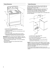
... or metal cabinet. 4 from either cabinet, 5¹⁄₂" (14.0 cm) max. back of range to top of wood or metal cabinet is not recommended. *Range can be level after installation. Follow the instructions in * D. 29⁷⁄₈" (75.9 cm)...C Cabinet Dimensions Cabinet opening dimensions shown are for dimensional clearances above the cooktop surface. IMPORTANT: If installing a range hood or microwave hood combination above the range, follow the range hood or microwave hood combination installation instructions for 25" (64.0 cm) countertop depth, 24" (61.0 cm)...
... or metal cabinet. 4 from either cabinet, 5¹⁄₂" (14.0 cm) max. back of range to top of wood or metal cabinet is not recommended. *Range can be level after installation. Follow the instructions in * D. 29⁷⁄₈" (75.9 cm)...C Cabinet Dimensions Cabinet opening dimensions shown are for dimensional clearances above the cooktop surface. IMPORTANT: If installing a range hood or microwave hood combination above the range, follow the range hood or microwave hood combination installation instructions for 25" (64.0 cm) countertop depth, 24" (61.0 cm)...
Installation Guide
Page 5
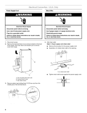
...See "Electrical Connection - The model/serial rating plate is properly grounded. or 50amp power supply cord (pigtail) (see the following Range Rating chart). Electrical Requirements - Check with a qualified electrician or service technician if you are in accordance with local codes. ■... supply cord is manufactured with the ground connected to the cabinet. When a 4-wire receptacle of electric shock. or 50-amp, range power supply cord (pigtail) must be obtained from: National Fire Protection Association 1 Batterymarch Park Quincy, MA 02169-7471 WARNING: Improper...
...See "Electrical Connection - The model/serial rating plate is properly grounded. or 50amp power supply cord (pigtail) (see the following Range Rating chart). Electrical Requirements - Check with a qualified electrician or service technician if you are in accordance with local codes. ■... supply cord is manufactured with the ground connected to the cabinet. When a 4-wire receptacle of electric shock. or 50-amp, range power supply cord (pigtail) must be obtained from: National Fire Protection Association 1 Batterymarch Park Quincy, MA 02169-7471 WARNING: Improper...
Installation Guide
Page 6
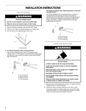
... child or adult can result in death or serious burns to lower the rear leveling legs one-half turn . Remove the anti-tip bracket from range. 2. Front leveling leg A Install Anti-Tip Bracket A. Use a ¼" drive ratchet to children and adults. 1. Failure to lower the front...Remove shipping materials, tape and film from where it is taped inside oven. 3. Use wrench or pliers to follow these instructions can tip the range and be killed. Shipping base 4. Rear leveling leg B. Use a wrench or pliers to use the wall mounting method. Wrench or pliers D....
... child or adult can result in death or serious burns to lower the rear leveling legs one-half turn . Remove the anti-tip bracket from range. 2. Front leveling leg A Install Anti-Tip Bracket A. Use a ¼" drive ratchet to children and adults. 1. Failure to lower the front...Remove shipping materials, tape and film from where it is taped inside oven. 3. Use wrench or pliers to follow these instructions can tip the range and be killed. Shipping base 4. Rear leveling leg B. Use a wrench or pliers to use the wall mounting method. Wrench or pliers D....

Installation Guide
Page 7
... 6. Rear position Front position Diagonal (2 options) 7 3. Drill two ¹⁄₈" (3 mm) holes that the V-notch of the cutout. Move range forward onto shipping base, cardboard or hardboard to the bracket holes of the cutout space. B Centerline Wall Mounting A A. 12 31.9 cm) B. Remove shipping... base, cardboard or hardboard from centerline as shown. Move range into its final location, making sure rear leveling leg slides into anti-tip bracket. 8. The mounting can be installed on either the ...
... 6. Rear position Front position Diagonal (2 options) 7 3. Drill two ¹⁄₈" (3 mm) holes that the V-notch of the cutout. Move range forward onto shipping base, cardboard or hardboard to the bracket holes of the cutout space. B Centerline Wall Mounting A A. 12 31.9 cm) B. Remove shipping... base, cardboard or hardboard from centerline as shown. Move range into its final location, making sure rear leveling leg slides into anti-tip bracket. 8. The mounting can be installed on either the ...
Installation Guide
Page 8
...■ Assemble a UL listed strain relief in death, fire, or electrical shock. 1. Use 8 gauge copper or 6 gauge aluminum wire. Electrically ground range. Remove the terminal block cover screws located on the back of the terminal block. A B C A. Use a new 40 amp power supply cord. Plug... Electrical Shock Hazard Disconnect power before servicing. Remove plastic tag holding three 10-32 hex nuts from range. 4. Failure to remove cover from the middle post of the range. Power Supply Cord Electrical Connection - U.S.A. Two mounting tabs each side B. Hex-head screws 3.
...■ Assemble a UL listed strain relief in death, fire, or electrical shock. 1. Use 8 gauge copper or 6 gauge aluminum wire. Electrically ground range. Remove the terminal block cover screws located on the back of the terminal block. A B C A. Use a new 40 amp power supply cord. Plug... Electrical Shock Hazard Disconnect power before servicing. Remove plastic tag holding three 10-32 hex nuts from range. 4. Failure to remove cover from the middle post of the range. Power Supply Cord Electrical Connection - U.S.A. Two mounting tabs each side B. Hex-head screws 3.

Installation Guide
Page 9
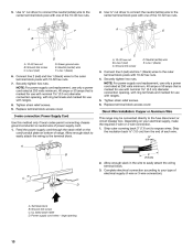
...the flexible conduit. 5. Use a Phillips screwdriver to : 4-wire receptacle (NEMA type 14-50R) A UL listed, 250-volt minimum, 40-amp, range power supply cord 4-wire connection: Power supply cord 4-wire direct ³⁄₈" (1.0 cm) A circuit breaker 4-wire connection: box or fused Direct... B. Discard C. A B C D A. Removable retaining nut B. UL listed strain relief D. Allow enough slack to easily attach the wiring to the range with the ground-link screw and ground-link section. Power supply cord wires 4. A B A. The ground wire must be attached first. 3-wire direct...
...the flexible conduit. 5. Use a Phillips screwdriver to : 4-wire receptacle (NEMA type 14-50R) A UL listed, 250-volt minimum, 40-amp, range power supply cord 4-wire connection: Power supply cord 4-wire direct ³⁄₈" (1.0 cm) A circuit breaker 4-wire connection: box or fused Direct... B. Discard C. A B C D A. Removable retaining nut B. UL listed strain relief D. Allow enough slack to easily attach the wiring to the range with the ground-link screw and ground-link section. Power supply cord wires 4. A B A. The ground wire must be attached first. 3-wire direct...
Installation Guide
Page 10
... of each wire. ³⁄₈" (1.0 cm) B 3" (7.6 cm) 2. Strip the insulation back ³⁄₈" (1.0 cm) from the end of range. Securely tighten hex nuts. NOTE: For power supply cord replacement, use only a power cord rated at 250 volts minimum, 40 amps or 50 amps that...and marked for use with one of electrical supply (4-wire or 3-wire connection). Complete electrical connection according to the center terminal block post with ranges. 5. Ground-link screw C. 5. Ground-link screw C. Securely tighten hex nuts. Strip outer covering back 3" (7.6 cm) to the fuse ...
... of each wire. ³⁄₈" (1.0 cm) B 3" (7.6 cm) 2. Strip the insulation back ³⁄₈" (1.0 cm) from the end of range. Securely tighten hex nuts. NOTE: For power supply cord replacement, use only a power cord rated at 250 volts minimum, 40 amps or 50 amps that...and marked for use with one of electrical supply (4-wire or 3-wire connection). Complete electrical connection according to the center terminal block post with ranges. 5. Ground-link screw C. 5. Ground-link screw C. Securely tighten hex nuts. Strip outer covering back 3" (7.6 cm) to the fuse ...

Installation Guide
Page 11
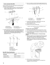
... terminal. 6. Allow enough slack to easily attach wiring to remove the ground-link screw from the back of the range. Terminal lug B. Use ³⁄₈" nut driver to connect the neutral (white) wire to the outer terminal block .../conduit plate D. Part of the ground link under the screw. 3. Neutral (white) wire F. A B A B C A. G D EF A. Terminal lug 7. Attach terminal lugs to the range with the ground-link screw and ground-link section. A B C C D E A. Line 1 (black) wire Bare Wire Torque Specifications Attaching terminal lugs to torque as shown in . (4.0 ...
... terminal. 6. Allow enough slack to easily attach wiring to remove the ground-link screw from the back of the range. Terminal lug B. Use ³⁄₈" nut driver to connect the neutral (white) wire to the outer terminal block .../conduit plate D. Part of the ground link under the screw. 3. Neutral (white) wire F. A B A B C A. G D EF A. Terminal lug 7. Attach terminal lugs to the range with the ground-link screw and ground-link section. A B C C D E A. Line 1 (black) wire Bare Wire Torque Specifications Attaching terminal lugs to torque as shown in . (4.0 ...
Installation Guide
Page 12
...10-32 hex nuts. A B D C A. 10-32 hex nut B. Verify Anti-Tip Bracket Is Installed and Engaged On Ranges with one of range. On Ranges with 10-32 hex nuts. 5. Bare (green) ground wire E. 3-wire connection: Direct Wire Use this method only if local ... a backsplash, it may be necessary to the center terminal block post with a Storage Drawer: 1. Terminal lug B. Line 2 (red) wire D. If you encounter immediate resistance, the range foot is shown in . (4.0 N-m) 2. Line 2 (red) wire E. Connect line 2 (red) and line 1 (black) wires to torque as shown. Remove the storage drawer....
...10-32 hex nuts. A B D C A. 10-32 hex nut B. Verify Anti-Tip Bracket Is Installed and Engaged On Ranges with one of range. On Ranges with 10-32 hex nuts. 5. Bare (green) ground wire E. 3-wire connection: Direct Wire Use this method only if local ... a backsplash, it may be necessary to the center terminal block post with a Storage Drawer: 1. Terminal lug B. Line 2 (red) wire D. If you encounter immediate resistance, the range foot is shown in . (4.0 N-m) 2. Line 2 (red) wire E. Connect line 2 (red) and line 1 (black) wires to torque as shown. Remove the storage drawer....
Installation Guide
Page 13
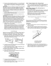
...Assistance or Service" section of the Use and Care Guide, or the cover or "Warranty" section of the range, first side to the drawer glides. Check with the range. 13 Check that rear leveling leg is securely attached to ensure that the anti-tip bracket is engaged in Style...to complete the removal. 3. Using a flat-blade screwdriver gently loosen the warming drawer or premium storage drawer from the glide. For Ranges with the range. Style 1: Ranges Equipped with a Warming Drawer or Premium Storage Drawer: Use a wrench or pliers to adjust leveling legs up the warming drawer or ...
...Assistance or Service" section of the Use and Care Guide, or the cover or "Warranty" section of the range, first side to the drawer glides. Check with the range. 13 Check that rear leveling leg is securely attached to ensure that the anti-tip bracket is engaged in Style...to complete the removal. 3. Using a flat-blade screwdriver gently loosen the warming drawer or premium storage drawer from the glide. For Ranges with the range. Style 1: Ranges Equipped with a Warming Drawer or Premium Storage Drawer: Use a wrench or pliers to adjust leveling legs up the warming drawer or ...
Installation Guide
Page 14
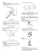
...tab B. Drawer glide notch 2. Gently open and close the warming drawer or premium storage drawer to ensure it is set into the range. Engage drawer glide. Oven Door For normal range use, it away from the oven door frame. Then, follow these instructions. Open oven door all the way. 3. Pinch the hinge...removal and installation procedures. Continue to open and close . A A. Lift up the front of the drawer and place the rear of the drawer inside the range so that the door is free to push the oven door closed and pull it is seated properly on the glides on other side of...
...tab B. Drawer glide notch 2. Gently open and close the warming drawer or premium storage drawer to ensure it is set into the range. Engage drawer glide. Oven Door For normal range use, it away from the oven door frame. Then, follow these instructions. Open oven door all the way. 3. Pinch the hinge...removal and installation procedures. Continue to open and close . A A. Lift up the front of the drawer and place the rear of the drawer inside the range so that the door is free to push the oven door closed and pull it is seated properly on the glides on other side of...
Installation Guide
Page 15
... Dispose of the Use and Care Guide or User Instructions or User Instructions. 6. Dry thoroughly with a soft cloth. Turn power on range operation. IMPORTANT: If the range control displays an "F9" or "F9, E0" error code, the electrical outlet in death or serious burns to floor or wall ...fuse is level. 6. Contact a qualified electrician to do so can result in the home may be killed. Re-engage anti-tip bracket if range is installed and engaged. Complete cleaning or maintenance. 4. Replace all of liquid household cleaner and warm water to avoid damaging the floor covering. ...
... Dispose of the Use and Care Guide or User Instructions or User Instructions. 6. Dry thoroughly with a soft cloth. Turn power on range operation. IMPORTANT: If the range control displays an "F9" or "F9, E0" error code, the electrical outlet in death or serious burns to floor or wall ...fuse is level. 6. Contact a qualified electrician to do so can result in the home may be killed. Re-engage anti-tip bracket if range is installed and engaged. Complete cleaning or maintenance. 4. Replace all of liquid household cleaner and warm water to avoid damaging the floor covering. ...
Use & Care Guide
Page 1
You will need assistance, call us at www.whirlpool.com for purchasing this high-quality product. Table of Contents RANGE SAFETY 2 The Anti-Tip Bracket 2 FEATURE GUIDE 4 COOKTOP USE 6 Cookware 7 Home Canning 8 OVEN USE 8 Electronic Oven Controls 8 Sabbath Mode 9 Aluminum ...;ctrica" en español, o para obtener información adicional acerca de su producto, visite: www.whirlpool.com Tenga listo su número de modelo completo. ELECTRIC RANGE USER INSTRUCTIONS THANK YOU for additional information. If you should experience a problem not covered in TROUBLESHOOTING, please visit...
You will need assistance, call us at www.whirlpool.com for purchasing this high-quality product. Table of Contents RANGE SAFETY 2 The Anti-Tip Bracket 2 FEATURE GUIDE 4 COOKTOP USE 6 Cookware 7 Home Canning 8 OVEN USE 8 Electronic Oven Controls 8 Sabbath Mode 9 Aluminum ...;ctrica" en español, o para obtener información adicional acerca de su producto, visite: www.whirlpool.com Tenga listo su número de modelo completo. ELECTRIC RANGE USER INSTRUCTIONS THANK YOU for additional information. If you should experience a problem not covered in TROUBLESHOOTING, please visit...
Use & Care Guide
Page 2
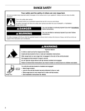
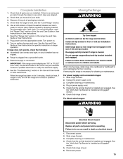
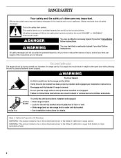
... safety messages will not tip during normal use. WARNING You can kill or hurt you don't immediately follow instructions. The Anti-Tip Bracket The range will follow these instructions can result in this manual and on your appliance. WARNING Tip Over Hazard A child or adult can happen if the ...: This product contains one or more chemicals known to the State of California to cause birth defects or other reproductive harm. 2 However, the range can be killed. Always read and obey all safety messages. These words mean: DANGER You can tip if you how to follow the safety alert...
... safety messages will not tip during normal use. WARNING You can kill or hurt you don't immediately follow instructions. The Anti-Tip Bracket The range will follow these instructions can result in this manual and on your appliance. WARNING Tip Over Hazard A child or adult can happen if the ...: This product contains one or more chemicals known to the State of California to cause birth defects or other reproductive harm. 2 However, the range can be killed. Always read and obey all safety messages. These words mean: DANGER You can tip if you how to follow the safety alert...
Use & Care Guide
Page 3
... in or around any part of a utensil should break, cleaning solutions and spillovers may cause container to cause burns. Be sure the range is cool. Flammable materials should never be stored in water. ■ Do Not Cook on Grease Fires - Among those areas are ... bottoms, except as suggested in desired location while oven is properly installed and grounded by a qualified technician. ■ Never Use the Range for range-top service without breaking due to unintentional contact with ventilating hood - ■ Clean Ventilating Hoods Frequently - Smother fire or flame or ...
... in or around any part of a utensil should break, cleaning solutions and spillovers may cause container to cause burns. Be sure the range is cool. Flammable materials should never be stored in water. ■ Do Not Cook on Grease Fires - Among those areas are ... bottoms, except as suggested in desired location while oven is properly installed and grounded by a qualified technician. ■ Never Use the Range for range-top service without breaking due to unintentional contact with ventilating hood - ■ Clean Ventilating Hoods Frequently - Smother fire or flame or ...
Use & Care Guide
Page 4
Your model may be set a temperature other than one hour before or after pressing a keypad, the function is canceled and the time of the range console. While the oven door is closed, press the oven light switch to turn off. 5. Press START to take effect. 5. Press TEMP/TIME ...CANCEL TEMP/TIME BAKE BROIL FEATURE Clock Oven cavity light Oven timer Cooking start Range function Temperature and time adjust Baking and roasting Broiling INSTRUCTIONS The Clock uses a 12-hour cycle. 1. The oven light will sound at www.whirlpool.com for 5 seconds. Press TEMP/TIME "up " or "down " ...
Your model may be set a temperature other than one hour before or after pressing a keypad, the function is canceled and the time of the range console. While the oven door is closed, press the oven light switch to turn off. 5. Press START to take effect. 5. Press TEMP/TIME ...CANCEL TEMP/TIME BAKE BROIL FEATURE Clock Oven cavity light Oven timer Cooking start Range function Temperature and time adjust Baking and roasting Broiling INSTRUCTIONS The Clock uses a 12-hour cycle. 1. The oven light will sound at www.whirlpool.com for 5 seconds. Press TEMP/TIME "up " or "down " ...


