
Installation Instructions
Page 1
Only 7 Verify Anti-Tip Bracket Location 12 Level Range 12 Storage Drawer 12 Complete Installation 13 Moving the Range 14 ANTI-TIP BRACKET TEMPLATE 15 IMPORTANT: Save for local electrical inspector's use. W10252706B U.S.A. U.S.A. Only 4 INSTALLATION INSTRUCTIONS 6 Unpack Range 6 Install Anti-Tip Bracket 6 Electrical Connection - INSTALLATION INSTRUCTIONS 30" (76 CM) FREESTANDING ELECTRIC RANGES Table of Contents RANGE SAFETY 2 INSTALLATION REQUIREMENTS 3 Tools and Parts 3 Location Requirements 3 Electrical Requirements -
Only 7 Verify Anti-Tip Bracket Location 12 Level Range 12 Storage Drawer 12 Complete Installation 13 Moving the Range 14 ANTI-TIP BRACKET TEMPLATE 15 IMPORTANT: Save for local electrical inspector's use. W10252706B U.S.A. U.S.A. Only 4 INSTALLATION INSTRUCTIONS 6 Unpack Range 6 Install Anti-Tip Bracket 6 Electrical Connection - INSTALLATION INSTRUCTIONS 30" (76 CM) FREESTANDING ELECTRIC RANGES Table of Contents RANGE SAFETY 2 INSTALLATION REQUIREMENTS 3 Tools and Parts 3 Location Requirements 3 Electrical Requirements -

Installation Instructions
Page 2
... of injury, and tell you don't immediately follow instructions. This symbol alerts you how to children and adults. 2 Reconnect the anti-tip bracket, if the range is the safety alert symbol. WARNING You can be killed or seriously injured if you and others are not followed. WARNING Tip Over Hazard A child...and either the word "DANGER" or "WARNING." These words mean: DANGER You can be killed. All safety messages will follow these instructions can tip the range and be killed or seriously injured if you what can kill or hurt you don't follow instructions.
... of injury, and tell you don't immediately follow instructions. This symbol alerts you how to children and adults. 2 Reconnect the anti-tip bracket, if the range is the safety alert symbol. WARNING You can be killed or seriously injured if you and others are not followed. WARNING Tip Over Hazard A child...and either the word "DANGER" or "WARNING." These words mean: DANGER You can be killed. All safety messages will follow these instructions can tip the range and be killed or seriously injured if you what can kill or hurt you don't follow instructions.

Installation Instructions
Page 3
...section. To install the antitip bracket shipped with any tools listed here. Mobile Home - Read and follow the instructions provided with the range, see "Install Anti-Tip Bracket" section. ■ Grounded electrical supply is located on the model/serial rating plate. Given dimensions...; A UL listed strain relief. See "Electrical Requirements" section. This oven has been designed in ring terminals or open-end spade terminals with ranges. Parts needed ■ Tape measure ■ ¼" drive ratchet ■ Flat-blade screwdriver ■ Level ■ Hammer ■ ...
...section. To install the antitip bracket shipped with any tools listed here. Mobile Home - Read and follow the instructions provided with the range, see "Install Anti-Tip Bracket" section. ■ Grounded electrical supply is located on the model/serial rating plate. Given dimensions...; A UL listed strain relief. See "Electrical Requirements" section. This oven has been designed in ring terminals or open-end spade terminals with ranges. Parts needed ■ Tape measure ■ ¼" drive ratchet ■ Flat-blade screwdriver ■ Level ■ Hammer ■ ...

Installation Instructions
Page 4
...If it is used, it will not fit the outlet, have a proper outlet installed by a qualified electrician. 4 IMPORTANT: If installing a range hood or microwave hood combination above the cooktop surface. Check with a qualified electrician or service technician if you are adequate and in doubt as .... D. 30¹⁄₈" (76.5 cm) min. Be sure that the ground path and wire gauge are for dimensional clearances above the range, follow the range hood or microwave hood combination installation instructions for 25" (64.0 cm) countertop depth, 24" (61.0 cm) base cabinet depth and 36" ...
...If it is used, it will not fit the outlet, have a proper outlet installed by a qualified electrician. 4 IMPORTANT: If installing a range hood or microwave hood combination above the cooktop surface. Check with a qualified electrician or service technician if you are adequate and in doubt as .... D. 30¹⁄₈" (76.5 cm) min. Be sure that the ground path and wire gauge are for dimensional clearances above the range, follow the range hood or microwave hood combination installation instructions for 25" (64.0 cm) countertop depth, 24" (61.0 cm) base cabinet depth and 36" ...

Installation Instructions
Page 5
...-end spade terminals with upturned ends, terminating in a NEMA Type 10-50P plug on the model/serial number rating plate. or 50-amp range power supply cord (pigtail). The model/serial number rating plate is connected to the proper electrical voltage and frequency as specified on the supply ...end. Grounding through the neutral conductor. or 50-amp, range power supply cord (pigtail) must be identified by a green or green/yellow cover and the neutral conductor by a link. Cord should be ...
...-end spade terminals with upturned ends, terminating in a NEMA Type 10-50P plug on the model/serial number rating plate. or 50-amp range power supply cord (pigtail). The model/serial number rating plate is connected to the proper electrical voltage and frequency as specified on the supply ...end. Grounding through the neutral conductor. or 50-amp, range power supply cord (pigtail) must be identified by a green or green/yellow cover and the neutral conductor by a link. Cord should be ...

Installation Instructions
Page 6
... not remove the shipping base at this manual. 2. A D C Install Anti-Tip Bracket WARNING Tip Over Hazard A child or adult can tip the range and be accessed by removing the warming drawer. Tape template into place. 4. B A. ¼" drive ratchet B. It will be necessary to lower the... C. Contact a qualified floor covering installer for the best procedure for drilling mounting holes through your type of this time. Before moving range, slide range onto shipping base, cardboard or hardboard. 1. Place template on the floor in cabinet opening is wider than that the left edge is...
... not remove the shipping base at this manual. 2. A D C Install Anti-Tip Bracket WARNING Tip Over Hazard A child or adult can tip the range and be accessed by removing the warming drawer. Tape template into place. 4. B A. ¼" drive ratchet B. It will be necessary to lower the... C. Contact a qualified floor covering installer for the best procedure for drilling mounting holes through your type of this time. Before moving range, slide range onto shipping base, cardboard or hardboard. 1. Place template on the floor in cabinet opening is wider than that the left edge is...

Installation Instructions
Page 7
... holes with screws provided. To mount anti-tip bracket to concrete or ceramic floor, use a 4.8 mm) masonry drill bit to remove cover from range. 3. Use a new 40 amp power supply cord. Disconnect power. 2. Pull cover down and toward you to drill 2 holes at the positions ... death, fire, or electrical shock. Remove template from the middle post of your local hardware store. Failure to the subfloor. Electrically ground range. Depending on the bracket template. Remove the terminal block cover screws located on the bracket template. To mount anti-tip bracket to follow...
... holes with screws provided. To mount anti-tip bracket to concrete or ceramic floor, use a 4.8 mm) masonry drill bit to remove cover from range. 3. Use a new 40 amp power supply cord. Disconnect power. 2. Pull cover down and toward you to drill 2 holes at the positions ... death, fire, or electrical shock. Remove template from the middle post of your local hardware store. Failure to the subfloor. Electrically ground range. Depending on the bracket template. Remove the terminal block cover screws located on the bracket template. To mount anti-tip bracket to follow...

Installation Instructions
Page 8
...) 3-wire (if 4-wire is not available) A. Metal ground strap B. A B A. Discard C. Save the ground-link screw and the end of the range. 4. Concuit ■ Tighten strain relief screw against the power supply cord. 4-wire direct ³⁄₈" (1.0 cm) A circuit breaker 4-wire connection:...under the screw. 8 Use a Phillips screwdriver to : 4-wire receptacle (NEMA type 14-50R) A UL listed, 250-volt minimum, 40-amp, range power supply cord 4-wire connection: Power supply cord A A. Add strain relief. Style 1: Power supply cord strain relief ■ Remove the knockout for...
...) 3-wire (if 4-wire is not available) A. Metal ground strap B. A B A. Discard C. Save the ground-link screw and the end of the range. 4. Concuit ■ Tighten strain relief screw against the power supply cord. 4-wire direct ³⁄₈" (1.0 cm) A circuit breaker 4-wire connection:...under the screw. 8 Use a Phillips screwdriver to : 4-wire receptacle (NEMA type 14-50R) A UL listed, 250-volt minimum, 40-amp, range power supply cord 4-wire connection: Power supply cord A A. Add strain relief. Style 1: Power supply cord strain relief ■ Remove the knockout for...

Installation Instructions
Page 9
...Tighten strain relief screws. 6. Feed the power supply cord through the strain relief on the cord/conduit plate on bottom of range. Use a Phillips screwdriver to connect the green ground wire from the power supply cord to neutral wire of the 10-32 ... E A. 10-32 hex nut B. Ground-link screw C. Green ground wire E. Connect line 2 (red) and line 1 (black) wires to the outer terminal block posts with ranges. 5. Replace terminal block access cover. Ground-link screw D. Neutral (white) wire E. Line 1 (black) 3. Connect line 2 (red) and line 1 (black) wires to ...
...Tighten strain relief screws. 6. Feed the power supply cord through the strain relief on the cord/conduit plate on bottom of range. Use a Phillips screwdriver to connect the green ground wire from the power supply cord to neutral wire of the 10-32 ... E A. 10-32 hex nut B. Ground-link screw C. Green ground wire E. Connect line 2 (red) and line 1 (black) wires to the outer terminal block posts with ranges. 5. Replace terminal block access cover. Ground-link screw D. Neutral (white) wire E. Line 1 (black) 3. Connect line 2 (red) and line 1 (black) wires to ...

Installation Instructions
Page 10
Depending on bottom of range. Allow enough slack to easily attach wiring to line 1 (black), neutral (white), and line 2 (red) wires. A B 3" (7.6 cm) 2. Ground... the end of terminal lugs. Line 2 (red) wire F. Direct Wire Installation: Copper or Aluminum Wire This range may be connected directly to the range with the ground-link screw and ground-link section. Strip outer covering back 3" (7.6 cm) to torque as... connection according to remove the ground-link screw from the end of the range. Securely tighten setscrew to expose wires. A A B B C A. Discard C.
Depending on bottom of range. Allow enough slack to easily attach wiring to line 1 (black), neutral (white), and line 2 (red) wires. A B 3" (7.6 cm) 2. Ground... the end of terminal lugs. Line 2 (red) wire F. Direct Wire Installation: Copper or Aluminum Wire This range may be connected directly to the range with the ground-link screw and ground-link section. Strip outer covering back 3" (7.6 cm) to torque as... connection according to remove the ground-link screw from the end of the range. Securely tighten setscrew to expose wires. A A B B C A. Discard C.

Installation Instructions
Page 11
... E. Ground-link screw C. Line 2 (red) wire E. Ground-link screw D. Connect line 2 (red) and line 1 (black) wires to the outer terminal block posts with one of range. Pull the wires through bottom of the 10-32 hex nuts. Terminal lug 4. Securely tighten hex nuts. 6. 6. Cord/conduit plate F D. Terminal lug 7. Attach terminal lugs...
... E. Ground-link screw C. Line 2 (red) wire E. Ground-link screw D. Connect line 2 (red) and line 1 (black) wires to the outer terminal block posts with one of range. Pull the wires through bottom of the 10-32 hex nuts. Terminal lug 4. Securely tighten hex nuts. 6. 6. Cord/conduit plate F D. Terminal lug 7. Attach terminal lugs...

Installation Instructions
Page 12
... by pressing the screwdriver handle toward the side of storage drawer 4. Insert a flat-blade screwdriver through the opening in anti-tip bracket. NOTE: Range must be removed. Repeat steps 2, 3, and 4, for the anti-tip bracket securely attached to side; Check that rear leveling leg is level.... Replace the storage drawer (on rack and check levelness of the range. ■ Look for the other side of the drawer clip. 2. Drawer clip 3. Storage Drawer The storage drawer can be level for ...
... by pressing the screwdriver handle toward the side of storage drawer 4. Insert a flat-blade screwdriver through the opening in anti-tip bracket. NOTE: Range must be removed. Repeat steps 2, 3, and 4, for the anti-tip bracket securely attached to side; Check that rear leveling leg is level.... Replace the storage drawer (on rack and check levelness of the range. ■ Look for the other side of the drawer clip. 2. Drawer clip 3. Storage Drawer The storage drawer can be level for ...

Installation Instructions
Page 13
... fuse is connected. ■ See "Troubleshooting" in its fully forward position. 2. or circuit breaker has not tripped. ■ Range is plugged into the closed position. 5. If range is fully engaged on both sides, slide the drawer back into an outlet. ■ Electrical supply is intact and tight; Slowly ... of the storage drawer to move the drawer stop notch past the drawer glides. Lift up the front of your tools. 3. Turn on range operation. See the Use and Care Guide for heat. Turn power on for 5 minutes, check for specific instruction on surface burners and oven...
... fuse is connected. ■ See "Troubleshooting" in its fully forward position. 2. or circuit breaker has not tripped. ■ Range is plugged into the closed position. 5. If range is fully engaged on both sides, slide the drawer back into an outlet. ■ Electrical supply is intact and tight; Slowly ... of the storage drawer to move the drawer stop notch past the drawer glides. Lift up the front of your tools. 3. Turn on range operation. See the Use and Care Guide for heat. Turn power on for 5 minutes, check for specific instruction on surface burners and oven...

Installation Instructions
Page 14
...installed: ■ Look for cleaning or maintenance: For power supply cord-connected ranges: 1. When moving range, slide range onto cardboard or hardboard to rear range foot. Electrical Shock Hazard Disconnect power before operating. Slide range forward. 3. Check that anti-tip bracket is installed: ■ Look for... the anti-tip bracket securely attached to children and adults. Check that range is under anti-tip bracket. 5. Failure to floor. ■ Slide range back so rear range foot is level. 14 Connect anti-tip bracket to avoid damaging the floor covering. ...
...installed: ■ Look for cleaning or maintenance: For power supply cord-connected ranges: 1. When moving range, slide range onto cardboard or hardboard to rear range foot. Electrical Shock Hazard Disconnect power before operating. Slide range forward. 3. Check that anti-tip bracket is installed: ■ Look for... the anti-tip bracket securely attached to children and adults. Check that range is under anti-tip bracket. 5. Failure to floor. ■ Slide range back so rear range foot is level. 14 Connect anti-tip bracket to avoid damaging the floor covering. ...

Owners Manual
Page 1
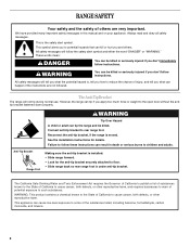
...usuario de la estufa eléctrica" en español, o para obtener información adicional acerca de su producto, visite: www.whirlpool.com Tenga listo su número de modelo completo. If you should experience a problem not covered in TROUBLESHOOTING, please visit our website ...at 1-800-253-1301. You will need assistance, call us at www.whirlpool.com for purchasing this high-quality product. Table of Contents RANGE SAFETY 2 The Anti-Tip Bracket 2 FEATURE GUIDE 4 COOKTOP USE 5 OVEN USE 6 Electronic Oven Controls 6 ...
...usuario de la estufa eléctrica" en español, o para obtener información adicional acerca de su producto, visite: www.whirlpool.com Tenga listo su número de modelo completo. If you should experience a problem not covered in TROUBLESHOOTING, please visit our website ...at 1-800-253-1301. You will need assistance, call us at www.whirlpool.com for purchasing this high-quality product. Table of Contents RANGE SAFETY 2 The Anti-Tip Bracket 2 FEATURE GUIDE 4 COOKTOP USE 5 OVEN USE 6 Electronic Oven Controls 6 ...
Owners Manual
Page 2
...warn of the substances listed, including benzene, formaldehyde, carbon monoxide, and toluene. 2 Always read and obey all safety messages. However, the range can be killed or seriously injured if you don't immediately follow the safety alert symbol and either the word "DANGER" or "WARNING." See ...the installation instructions for the anti-tip bracket securely attached to floor. • Slide range back so rear range foot is under anti-tip bracket. WARNING: This product contains a chemical known to the open door without the antitip bracket fastened...
...warn of the substances listed, including benzene, formaldehyde, carbon monoxide, and toluene. 2 Always read and obey all safety messages. However, the range can be killed or seriously injured if you don't immediately follow the safety alert symbol and either the word "DANGER" or "WARNING." See ...the installation instructions for the anti-tip bracket securely attached to floor. • Slide range back so rear range foot is under anti-tip bracket. WARNING: This product contains a chemical known to the open door without the antitip bracket fastened...

Owners Manual
Page 3
...may become hot enough to damage. ■ Protective Liners - No commercial oven cleaner or oven liner protective coating of any part of the range. ■ Wear Proper Apparel - The use , do not let potholder contact hot heating element in the manual. Interior surfaces of Oven... near units until they have had sufficient time to unintentional contact with ventilating hood - ■ Clean Ventilating Hoods Frequently - The range is cool. Heating elements should break, cleaning solutions and spillovers may result in desired location while oven is equipped with one or ...
...may become hot enough to damage. ■ Protective Liners - No commercial oven cleaner or oven liner protective coating of any part of the range. ■ Wear Proper Apparel - The use , do not let potholder contact hot heating element in the manual. Interior surfaces of Oven... near units until they have had sufficient time to unintentional contact with ventilating hood - ■ Clean Ventilating Hoods Frequently - The range is cool. Heating elements should break, cleaning solutions and spillovers may result in desired location while oven is equipped with one or ...
Owners Manual
Page 4
... to this manual or the Frequently Asked Questions (FAQs) section of our website at end of day, including a.m. The oven light will sound at www.whirlpool.com for the change the temperature repeat Step 2. The oven light will appear in the display. 3. Repeat to clear the display. 7. CLOCK Clock The ... in oven more information and helpful tips for more than 350°F (175°C) in hours or minutes up to set the length of the range. Push START. 5. OVEN LIGHT (on when the oven door is running, but not in food poisoning or sickness. SELF-CLEAN Self-clean cycle See ...
... to this manual or the Frequently Asked Questions (FAQs) section of our website at end of day, including a.m. The oven light will sound at www.whirlpool.com for the change the temperature repeat Step 2. The oven light will appear in the display. 3. Repeat to clear the display. 7. CLOCK Clock The ... in oven more information and helpful tips for more than 350°F (175°C) in hours or minutes up to set the length of the range. Push START. 5. OVEN LIGHT (on when the oven door is running, but not in food poisoning or sickness. SELF-CLEAN Self-clean cycle See ...
Owners Manual
Page 5
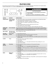
... glow as long as any surface cooking area is too hot to be at 170°F (75°C) for an oven function with a delayed start Range function Temperature and time adjust INSTRUCTIONS 1. Press BROIL. 3. Press START. 5. Press START. 4. To set a temperature other than ½" (1.3 cm) outside the ...300°F and 525°F (150°C and 275°C). 4. Press WARM. 2. The Start Time keypad is displayed. REMEMBER: When range is on some models) during the Self-Cleaning cycle, the entire cooktop area may not bake properly. Use cookware about the same size as breads...
... glow as long as any surface cooking area is too hot to be at 170°F (75°C) for an oven function with a delayed start Range function Temperature and time adjust INSTRUCTIONS 1. Press BROIL. 3. Press START. 5. Press START. 4. To set a temperature other than ½" (1.3 cm) outside the ...300°F and 525°F (150°C and 275°C). 4. Press WARM. 2. The Start Time keypad is displayed. REMEMBER: When range is on some models) during the Self-Cleaning cycle, the entire cooktop area may not bake properly. Use cookware about the same size as breads...
Owners Manual
Page 7
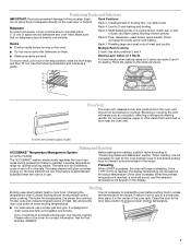
... vent (ceramic glass model) Baking and Roasting ACCUBAKE® Temperature Management System (on the racks as a guide. If you would like to maintain a precise temperature range for 2-rack baking and broiling. Make sure that could melt or burn near the oven vent. Blocking or covering the vent will not. This feature...
... vent (ceramic glass model) Baking and Roasting ACCUBAKE® Temperature Management System (on the racks as a guide. If you would like to maintain a precise temperature range for 2-rack baking and broiling. Make sure that could melt or burn near the oven vent. Blocking or covering the vent will not. This feature...


