Installation Guide
Page 1
U.S.A. Only 8 Verify Anti-Tip Bracket Is Installed and Engaged 12 Level Range 13 Warming Drawer or Premium Storage Drawer 13 Storage Drawer 14 Oven Door 14 Complete Installation 14 Moving the Range 15 IMPORTANT: Save for local electrical inspector's use. U.S.A. W10403811C Only 5 INSTALLATION INSTRUCTIONS 6 Unpack Range 6 Install Anti-Tip Bracket 6 Electrical Connection - INSTALLATION INSTRUCTIONS 30" (76 CM) FREESTANDING ELECTRIC RANGES Table of Contents RANGE SAFETY 2 INSTALLATION REQUIREMENTS 3 Tools and Parts 3 Location Requirements 3 Electrical Requirements -
U.S.A. Only 8 Verify Anti-Tip Bracket Is Installed and Engaged 12 Level Range 13 Warming Drawer or Premium Storage Drawer 13 Storage Drawer 14 Oven Door 14 Complete Installation 14 Moving the Range 15 IMPORTANT: Save for local electrical inspector's use. U.S.A. W10403811C Only 5 INSTALLATION INSTRUCTIONS 6 Unpack Range 6 Install Anti-Tip Bracket 6 Electrical Connection - INSTALLATION INSTRUCTIONS 30" (76 CM) FREESTANDING ELECTRIC RANGES Table of Contents RANGE SAFETY 2 INSTALLATION REQUIREMENTS 3 Tools and Parts 3 Location Requirements 3 Electrical Requirements -
Installation Guide
Page 3
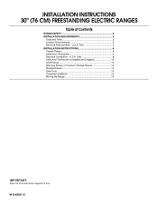
...codes and ordinances. ■ It is not applicable, use with your cabinets, check with ranges. Check existing electrical supply. If cabinet storage is to be provided, the risk can be reduced by installing a range hood that projects horizontally a minimum of 5" (12.7 cm) beyond the bottom of ...either side of the drawer. ■ To eliminate the risk of UL and CSA International and complies with the range, see "Install Anti-Tip Bracket" section. ■ Grounded electrical supply is installed in a mobile home, it must be secured per the instructions in a mobile home installation....
...codes and ordinances. ■ It is not applicable, use with your cabinets, check with ranges. Check existing electrical supply. If cabinet storage is to be provided, the risk can be reduced by installing a range hood that projects horizontally a minimum of 5" (12.7 cm) beyond the bottom of ...either side of the drawer. ■ To eliminate the risk of UL and CSA International and complies with the range, see "Install Anti-Tip Bracket" section. ■ Grounded electrical supply is installed in a mobile home, it must be secured per the instructions in a mobile home installation....

Installation Guide
Page 5
...Dimensions" in a risk of the above code standards can result in the "Location Requirements" section. or 50-amp range power supply cord (pigtail). A copy of electric shock. Only" section. The fourth (grounding) conductor must be moved if servicing is less than the total connected load...codes and ordinances. Connectors on the appliance end must be provided at least 4 ft (1.22 m) long. ■ This range is connected to the cabinet. Electrical Requirements - or 50-amp, range power supply cord (pigtail) must be used , a matching UL listed, 4-wire, 250-volt, 40- U.S.A. Do ...
...Dimensions" in a risk of the above code standards can result in the "Location Requirements" section. or 50-amp range power supply cord (pigtail). A copy of electric shock. Only" section. The fourth (grounding) conductor must be moved if servicing is less than the total connected load...codes and ordinances. Connectors on the appliance end must be provided at least 4 ft (1.22 m) long. ■ This range is connected to the cabinet. Electrical Requirements - or 50-amp, range power supply cord (pigtail) must be used , a matching UL listed, 4-wire, 250-volt, 40- U.S.A. Do ...

Installation Guide
Page 7
... screwdriver, mount anti-tip bracket to allow for final electrical connections. Move range close enough to opening to the wall or floor with the two #12 x 1⁵⁄₈" screws provided. 6. Move range forward onto shipping base, cardboard or hardboard to continue installing the range using the following installation instructions. 7 Rear position Wall Mounting...
... screwdriver, mount anti-tip bracket to allow for final electrical connections. Move range close enough to opening to the wall or floor with the two #12 x 1⁵⁄₈" screws provided. 6. Move range forward onto shipping base, cardboard or hardboard to continue installing the range using the following installation instructions. 7 Rear position Wall Mounting...

Installation Guide
Page 8
... terminal block cover screws located on the back of the terminal block. Failure to remove cover from the middle post of the range. Add strain relief. 8 A B C A. Power Supply Cord Electrical Connection - Use a new 40 amp power supply cord. Electrically ground range. Hex-head screws 3. Remove plastic tag holding three 10-32 hex nuts from...
... terminal block cover screws located on the back of the terminal block. Failure to remove cover from the middle post of the range. Add strain relief. 8 A B C A. Power Supply Cord Electrical Connection - Use a new 40 amp power supply cord. Electrically ground range. Hex-head screws 3. Remove plastic tag holding three 10-32 hex nuts from...

Installation Guide
Page 9
... relief D. Metal ground strap B. Terminal block B. Discard C. Save the ground-link screw and the end of electrical connection: 4-wire (recommended) 3-wire (if 4-wire is not available) Electrical Connection Options If your type of the ground link under the screw. 3. A B 5" (12.7 cm) ...3-wire receptacle (NEMA type 10-50R) A UL listed, 250-volt minimum, 40-amp, range power supply cord 3-wire connection: Power supply cord C ...
... relief D. Metal ground strap B. Terminal block B. Discard C. Save the ground-link screw and the end of electrical connection: 4-wire (recommended) 3-wire (if 4-wire is not available) Electrical Connection Options If your type of the ground link under the screw. 3. A B 5" (12.7 cm) ...3-wire receptacle (NEMA type 10-50R) A UL listed, 250-volt minimum, 40-amp, range power supply cord 3-wire connection: Power supply cord C ...

Installation Guide
Page 10
...to connect the neutral (white) wire to the center terminal block post with one of range. Line 1 (black) 6. Feed the power supply cord through the neutral A. Depending on your type of electrical supply (4-wire or 3-wire connection). 4-wire Connection: Direct Wire Use this method only ...codes prohibit grounding through the strain relief on the cord/conduit plate on bottom of the 10-32 hex nuts. Line 1 (black) 3. Complete electrical connection according to neutral wire of each wire. ³⁄₈" (1.0 cm) 3" (7.6 cm) 2. The ground wire must be connected ...
...to connect the neutral (white) wire to the center terminal block post with one of range. Line 1 (black) 6. Feed the power supply cord through the neutral A. Depending on your type of electrical supply (4-wire or 3-wire connection). 4-wire Connection: Direct Wire Use this method only ...codes prohibit grounding through the strain relief on the cord/conduit plate on bottom of the 10-32 hex nuts. Line 1 (black) 3. Complete electrical connection according to neutral wire of each wire. ³⁄₈" (1.0 cm) 3" (7.6 cm) 2. The ground wire must be connected ...
Installation Guide
Page 14
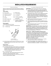
...drawer stop . 3. Turn on the bottom of the drawer inside the range so that you have all parts are placed in the drawer glide. 3. IMPORTANT: If the range control displays an "F9" or "F9, E0" error code, the electrical outlet in the home may be removed. Insert both sides. Lift up... to see which step was skipped. 2. Continue to push the oven door closed and pull it is free to verify the electrical supply. ■ See the "Troubleshooting" section in the range Use and Care Guide or User Instructions. 7. The oven door is level. Repeat on . 8. For more information, read ...
...drawer stop . 3. Turn on the bottom of the drawer inside the range so that you have all parts are placed in the drawer glide. 3. IMPORTANT: If the range control displays an "F9" or "F9, E0" error code, the electrical outlet in the home may be removed. Insert both sides. Lift up... to see which step was skipped. 2. Continue to push the oven door closed and pull it is free to verify the electrical supply. ■ See the "Troubleshooting" section in the range Use and Care Guide or User Instructions. 7. The oven door is level. Repeat on . 8. For more information, read ...

Installation Guide
Page 15
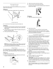
... or serious burns to follow these instructions can result in death or electrical shock. 1. Unplug the power supply cord. 3. Electrical Shock Hazard Disconnect power before operating. Check that range is level. 6. Replace all parts and panels before servicing. Do not operate range without anti-tip bracket installed and engaged. Complete cleaning or maintenance. 4. Complete...
... or serious burns to follow these instructions can result in death or electrical shock. 1. Unplug the power supply cord. 3. Electrical Shock Hazard Disconnect power before operating. Check that range is level. 6. Replace all parts and panels before servicing. Do not operate range without anti-tip bracket installed and engaged. Complete cleaning or maintenance. 4. Complete...
Use & Care Guide
Page 1
... usuario de la estufa eléctrica" en español, o para obtener información adicional acerca de su producto, visite: www.whirlpool.com Tenga listo su número de modelo completo. If you still need your model and serial number located on some models 10... RANGE CARE 11 Self-Cleaning Cycle (on the oven frame behind the storage drawer panel. You will need assistance, call us at www.whirlpool.com for purchasing this high-quality product. ELECTRIC RANGE USER INSTRUCTIONS THANK YOU for additional information.
... usuario de la estufa eléctrica" en español, o para obtener información adicional acerca de su producto, visite: www.whirlpool.com Tenga listo su número de modelo completo. If you still need your model and serial number located on some models 10... RANGE CARE 11 Self-Cleaning Cycle (on the oven frame behind the storage drawer panel. You will need assistance, call us at www.whirlpool.com for purchasing this high-quality product. ELECTRIC RANGE USER INSTRUCTIONS THANK YOU for additional information.

Use & Care Guide
Page 3
...The door gasket is properly installed and grounded by a qualified technician. ■ Never Use the Range for range-top service without breaking due to the sudden change in ignition of electric shock, or fire. ■ Glazed Cooking Utensils - TO CHECK IF THE DEVICES ARE INSTALLED PROPERLY...For units with one or more surface units of the range unless specifically recommended in Place - IMPORTANT SAFETY INSTRUCTIONS WARNING: To reduce the risk of fire, electrical shock, injury to persons, or damage when using the range. ■ User Servicing - All other flammable materials ...
...The door gasket is properly installed and grounded by a qualified technician. ■ Never Use the Range for range-top service without breaking due to the sudden change in ignition of electric shock, or fire. ■ Glazed Cooking Utensils - TO CHECK IF THE DEVICES ARE INSTALLED PROPERLY...For units with one or more surface units of the range unless specifically recommended in Place - IMPORTANT SAFETY INSTRUCTIONS WARNING: To reduce the risk of fire, electrical shock, injury to persons, or damage when using the range. ■ User Servicing - All other flammable materials ...
Use & Care Guide
Page 13
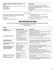
... breaker is a standard 40-watt appliance bulb. Cookware is on. Control lock is not the proper size. The electrical outlet in knob before cleaning. Level the range. Press and hold START TIME for 10 seconds to exit Demo Mode. See "Electronic Oven Controls" section. If the...set . The element may be cleaned when oven cools. See "Oven Temperature Control" in the "Electronic Oven Controls" section. www.whirlpool.com Operation PROBLEM Nothing will operate Cooktop will not operate Oven temperature too high or too low Oven indicator lights flash POSSIBLE CAUSES Power ...
... breaker is a standard 40-watt appliance bulb. Cookware is on. Control lock is not the proper size. The electrical outlet in knob before cleaning. Level the range. Press and hold START TIME for 10 seconds to exit Demo Mode. See "Electronic Oven Controls" section. If the...set . The element may be cleaned when oven cools. See "Oven Temperature Control" in the "Electronic Oven Controls" section. www.whirlpool.com Operation PROBLEM Nothing will operate Cooktop will not operate Oven temperature too high or too low Oven indicator lights flash POSSIBLE CAUSES Power ...


