
Warranty Information
Page 1
... to Whirlpool within 30 days from the date of purchase. 6. Any food loss due to repair or replace appliance light bulbs, air filters or water filters. The removal and reinstallation of your major appliance if it is used in the country in materials or workmanship. Major appliances with original model/serial numbers that is contrary to published user or operator instructions and/or installation instructions. 4. If outside the 50 United...
... to Whirlpool within 30 days from the date of purchase. 6. Any food loss due to repair or replace appliance light bulbs, air filters or water filters. The removal and reinstallation of your major appliance if it is used in the country in materials or workmanship. Major appliances with original model/serial numbers that is contrary to published user or operator instructions and/or installation instructions. 4. If outside the 50 United...
Installation Guide
Page 2
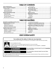
...2 INSTALLATION REQUIREMENTS 4 Tools and Parts 4 Location Requirements 4 Electrical Requirements 7 Venting Requirements 7 INSTALLATION INSTRUCTIONS 8 Venting Methods 8 Install Vent System 9 Rear Mounting-Blower Motor 11 Complete Installation 12 Make Electrical Connections 13 Check Operation 14 VENT SYSTEM USE 14 Operating Downdraft Vent 15 VENT SYSTEM CARE 15 Surface of Downdraft Vent 15 Filters 15 WIRING DIAGRAM 16 ASSISTANCE OR SERVICE 17 In the U.S.A 17 In Canada 17 Accessories 17 WARRANTY 18 TABLE DES MATIÈRES SÉCURITÉ DU SYSTÈME DE VENTILATION...
...2 INSTALLATION REQUIREMENTS 4 Tools and Parts 4 Location Requirements 4 Electrical Requirements 7 Venting Requirements 7 INSTALLATION INSTRUCTIONS 8 Venting Methods 8 Install Vent System 9 Rear Mounting-Blower Motor 11 Complete Installation 12 Make Electrical Connections 13 Check Operation 14 VENT SYSTEM USE 14 Operating Downdraft Vent 15 VENT SYSTEM CARE 15 Surface of Downdraft Vent 15 Filters 15 WIRING DIAGRAM 16 ASSISTANCE OR SERVICE 17 In the U.S.A 17 In Canada 17 Accessories 17 WARRANTY 18 TABLE DES MATIÈRES SÉCURITÉ DU SYSTÈME DE VENTILATION...
Installation Guide
Page 3
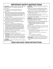
... not vent exhaust air into spaces within walls or ceilings, attics or into wall or ceiling; Boilovers cause smoking and greasy spillovers that may be vented outdoors. Heat oils slowly on fan or filter. ■ Use proper pan size. Grease should not be done by qualified person(s) in accordance with all applicable codes and standards, including fire-rated construction. ■ Do not operate any solid-state speed control...
... not vent exhaust air into spaces within walls or ceilings, attics or into wall or ceiling; Boilovers cause smoking and greasy spillovers that may be vented outdoors. Heat oils slowly on fan or filter. ■ Use proper pan size. Grease should not be done by qualified person(s) in accordance with all applicable codes and standards, including fire-rated construction. ■ Do not operate any solid-state speed control...
Installation Guide
Page 4
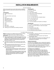
... compound Parts Needed ■ UL listed or CSA approved ½" (12.7 mm) conduit connector ■ Wall or roof cap with damper to comply with local codes. 4 It is located on the model/serial rating plate. The model/serial rating plate is the installer's responsibility to match vent system ■ Vent system ■ Home power supply cable ■ UL listed wire connectors (3) ■ Vent clamps/duct tape as required Location Requirements NOTE: Downdraft vent is 13" (33 cm). Cabinet Construction: Downdraft vent is required. Overhead cabinets installed at...
... compound Parts Needed ■ UL listed or CSA approved ½" (12.7 mm) conduit connector ■ Wall or roof cap with damper to comply with local codes. 4 It is located on the model/serial rating plate. The model/serial rating plate is the installer's responsibility to match vent system ■ Vent system ■ Home power supply cable ■ UL listed wire connectors (3) ■ Vent clamps/duct tape as required Location Requirements NOTE: Downdraft vent is 13" (33 cm). Cabinet Construction: Downdraft vent is required. Overhead cabinets installed at...
Installation Guide
Page 5
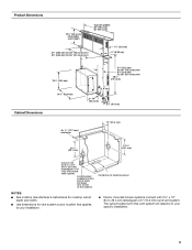
... cooktop cutout NOTES: ■ See cooktop manufacturer's instructions for cooktop cutout depth and width. ■ Use dimensions for this vent system will depend on your installation. ■ Interior mounted blower systems connect with 3¹⁄₄" x 10" (8.3 x 25.4 cm) rectangular or 6" (15.2 cm) round vent system. Centerline of the cabinet. The cutout locations for vent system cutout location that applies to your specific installation. 5 Product Dimensions 13¹⁄₂" (34.3 cm) retractable vent height...
... cooktop cutout NOTES: ■ See cooktop manufacturer's instructions for cooktop cutout depth and width. ■ Use dimensions for this vent system will depend on your installation. ■ Interior mounted blower systems connect with 3¹⁄₄" x 10" (8.3 x 25.4 cm) rectangular or 6" (15.2 cm) round vent system. Centerline of the cabinet. The cutout locations for vent system cutout location that applies to your specific installation. 5 Product Dimensions 13¹⁄₂" (34.3 cm) retractable vent height...
Installation Guide
Page 6
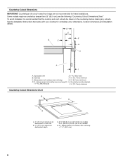
See the Installation Instructions that the cooktop and vent cutouts be drawn on 36" (91.4 cm) models D. Countertop and backsplash + 1 46.2 mm] (E) I A. Cooktop F. ½" (12.7 mm) minimum C. Some models require a countertop deeper than 25" (63.5 cm); see the following "Countertop Cutout Dimensions Chart." D E F B C G H A I . ½" (12.7 mm) minimum Countertop Cutout Dimensions Chart B D C A A. ½" (12.7 mm) minimum to backsplash or rear wall B 19.1 mm) maximum backsplash depth C. 27¹⁄...
See the Installation Instructions that the cooktop and vent cutouts be drawn on 36" (91.4 cm) models D. Countertop and backsplash + 1 46.2 mm] (E) I A. Cooktop F. ½" (12.7 mm) minimum C. Some models require a countertop deeper than 25" (63.5 cm); see the following "Countertop Cutout Dimensions Chart." D E F B C G H A I . ½" (12.7 mm) minimum Countertop Cutout Dimensions Chart B D C A A. ½" (12.7 mm) minimum to backsplash or rear wall B 19.1 mm) maximum backsplash depth C. 27¹⁄...
Installation Guide
Page 7
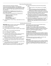
... cold air side of the thermal break. The model/serial plate is located on the model/serial rating plate. Recommended vent system length: For either interior-mounted or exterior-mounted blower installations, the vent system length should not exceed the maximum lengths listed in the vent system. ■ Use caulking tape to aluminum. If it is recommended that a qualified electrician determine that the electrical installation is proper clearance within the wall or floor before making exhaust vent cutouts. ■ Use...
... cold air side of the thermal break. The model/serial plate is located on the model/serial rating plate. Recommended vent system length: For either interior-mounted or exterior-mounted blower installations, the vent system length should not exceed the maximum lengths listed in the vent system. ■ Use caulking tape to aluminum. If it is recommended that a qualified electrician determine that the electrical installation is proper clearance within the wall or floor before making exhaust vent cutouts. ■ Use...
Installation Guide
Page 8
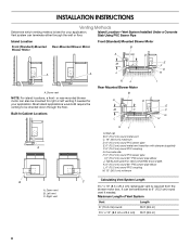
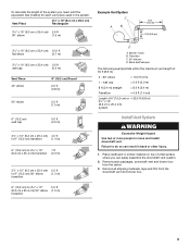
...B A. Maximum Length of Vent System Vent Length 6" (15.2 cm) round 35 ft (8.9 m) 3¹⁄₄" x 10" (8.3 cm x 25.4 cm) 35 ft (8.9 m) 8 Island Location-Vent System Installed Under a Concrete Slab Using PVC Sewer Pipe Island Location Front (Standard)-Mounted Blower Motor Rear-Mounted Blower Motor Front (Standard) Mounted Blower Motor B A D M C A A A. INSTALLATION INSTRUCTIONS Venting Methods Determine which venting method is required from the blower motor box. Most island applications would still require the venting to 6" (15.2 cm) round vent if needed for...
...B A. Maximum Length of Vent System Vent Length 6" (15.2 cm) round 35 ft (8.9 m) 3¹⁄₄" x 10" (8.3 cm x 25.4 cm) 35 ft (8.9 m) 8 Island Location-Vent System Installed Under a Concrete Slab Using PVC Sewer Pipe Island Location Front (Standard)-Mounted Blower Motor Rear-Mounted Blower Motor Front (Standard) Mounted Blower Motor B A D M C A A A. INSTALLATION INSTRUCTIONS Venting Methods Determine which venting method is required from the blower motor box. Most island applications would still require the venting to 6" (15.2 cm) round vent if needed for...
Installation Guide
Page 9
...) 90° elbow (1.5 m) transition 6" (15.2 cm) to do so can easily assemble the downdraft vent system. 2. Back draft damper The following example falls within the maximum vent length of 6" (15.2 cm) or = 22.5 ft (6.8 m) 3¹⁄₄" x 10" (8.3 cm x 25.4 cm) system Install Vent System WARNING Excessive Weight Hazard Use two or more people to move and install downdraft vent. Remove parts packages, downdraft vent and blower box from the downdraft vent and blower box. 9 Failure...
...) 90° elbow (1.5 m) transition 6" (15.2 cm) to do so can easily assemble the downdraft vent system. 2. Back draft damper The following example falls within the maximum vent length of 6" (15.2 cm) or = 22.5 ft (6.8 m) 3¹⁄₄" x 10" (8.3 cm x 25.4 cm) system Install Vent System WARNING Excessive Weight Hazard Use two or more people to move and install downdraft vent. Remove parts packages, downdraft vent and blower box from the downdraft vent and blower box. 9 Failure...
Installation Guide
Page 10
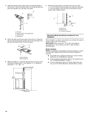
... Vent Direction Is Best For Your Installation When installed in down position, a wall or roof cap with blower in a cabinet, vent system can exhaust through the bottom, right or left or right venting is shipped with a damper at each support leg. 4. B A C 7. A B A. Measure distance "X" from the cabinet floor to lock into place. Bottom Venting: NOTE: If installing the vent damper in the down venting position so no modification is required. ■ If rear mounting of the blower motor...
... Vent Direction Is Best For Your Installation When installed in down position, a wall or roof cap with blower in a cabinet, vent system can exhaust through the bottom, right or left or right venting is shipped with a damper at each support leg. 4. B A C 7. A B A. Measure distance "X" from the cabinet floor to lock into place. Bottom Venting: NOTE: If installing the vent damper in the down venting position so no modification is required. ■ If rear mounting of the blower motor...
Installation Guide
Page 11
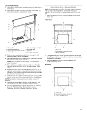
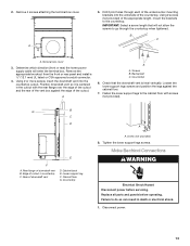
... the downdraft vent system on its back. 2. The blower motor box assembly can be used. 6. Motor mounting screws (4) E. Remove 3 screws and the vent cover plate from the left or right side to the chosen venting direction and secure to the back of the motor box and set blower motor box aside. 3. NOTE: Reinstall the electrical wiring connection to the "Complete Installation" section. Otherwise, go to the face of the blower motor box. Front View A A A D E A. Remove 4 screws from the mounting flange of the motor box that...
... the downdraft vent system on its back. 2. The blower motor box assembly can be used. 6. Motor mounting screws (4) E. Remove 3 screws and the vent cover plate from the left or right side to the chosen venting direction and secure to the back of the motor box and set blower motor box aside. 3. NOTE: Reinstall the electrical wiring connection to the "Complete Installation" section. Otherwise, go to the face of the blower motor box. Front View A A A D E A. Remove 4 screws from the mounting flange of the motor box that...
Installation Guide
Page 12
... screws on the rear of the vent box. Blower motor box 6. Place the wire assembly through the slot in the blower motor box, using the 6 screws previously removed from the wire mounting plate. Install the wire mounting plate to the vent box and secure using the 4 screws previously removed. 11. Go to "3¹⁄₄" x 10" (8.3 x 25.4 cm) back draft damper" or "6" (15.2 cm) round vent transition with the keyhole slots over the 2 shoulder screws, align the mounting holes, and secure the cover box to the wire mounting plate...
... screws on the rear of the vent box. Blower motor box 6. Place the wire assembly through the slot in the blower motor box, using the 6 screws previously removed from the wire mounting plate. Install the wire mounting plate to the vent box and secure using the 4 screws previously removed. 11. Go to "3¹⁄₄" x 10" (8.3 x 25.4 cm) back draft damper" or "6" (15.2 cm) round vent transition with the keyhole slots over the 2 shoulder screws, align the mounting holes, and secure the cover box to the wire mounting plate...
Installation Guide
Page 13
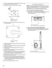
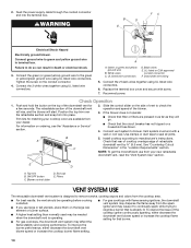
...;⁄₂" (12.7 mm) UL listed or CSA approved conduit connector. 4. Rear flange of downdraft vent D. Rear of downdraft vent B. Loosen the lower support legs screws and position the legs against the edge of the undercounter mounting brackets into the countertop cutout. Using 2 screws (not provided) of the appropriate length, mount the brackets to go through each of the cutout. Screws B. Replace all parts and panels before servicing. B C A. Check that will enter the terminal box.
...;⁄₂" (12.7 mm) UL listed or CSA approved conduit connector. 4. Rear flange of downdraft vent D. Rear of downdraft vent B. Loosen the lower support legs screws and position the legs against the edge of the undercounter mounting brackets into the countertop cutout. Using 2 screws (not provided) of the appropriate length, mount the brackets to go through each of the cutout. Screws B. Replace all parts and panels before servicing. B C A. Check that will enter the terminal box.
Installation Guide
Page 14
... cable through the conduit connector and into place. Slide the control slider on the large rear element or burner surface. ■ A higher heat setting than normally used may be operating before cooking is already lit. If the blower does not operate: ■ Check that the circuit breaker has not tripped or a household fuse blown. 4. UL listed wire connectors D. See "Countertop Cutout Dimensions" in terminal box. 2. The retractable section of retractable downdraft vent...
... cable through the conduit connector and into place. Slide the control slider on the large rear element or burner surface. ■ A higher heat setting than normally used may be operating before cooking is already lit. If the blower does not operate: ■ Check that the circuit breaker has not tripped or a household fuse blown. 4. UL listed wire connectors D. See "Countertop Cutout Dimensions" in terminal box. 2. The retractable section of retractable downdraft vent...
Installation Guide
Page 15
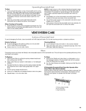
... to seep inside the downdraft vent while it will improve the operating efficiency of the retractable downdraft vent. Remove each filter by making sure that allows liquids to operate until the filter is properly installed. Repeat steps 1-5 for the downdraft vent to adjust the blower motor speed. 3. When the filter is removed, the microswitch behind the filter is operating. 2. Immediately turn the downdraft vent off the downdraft vent at the circuit breaker box or fuse box. This will go. Reinstall...
... to seep inside the downdraft vent while it will improve the operating efficiency of the retractable downdraft vent. Remove each filter by making sure that allows liquids to operate until the filter is properly installed. Repeat steps 1-5 for the downdraft vent to adjust the blower motor speed. 3. When the filter is removed, the microswitch behind the filter is operating. 2. Immediately turn the downdraft vent off the downdraft vent at the circuit breaker box or fuse box. This will go. Reinstall...
Installation Guide
Page 16
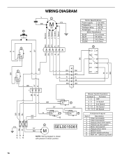
... drive motor 7 Blower motor 8 Blower speed switches 9 Start sw. - Description 1 Filter microswitch 2 Filter microswitch 3 Plenum down 16 Com N.C. 4 BU BR BR BK 1 23 Y/G G LN W GY 6 SEL0015061 BU NOTE: Wiring diagram is drawn with plenum in down position. Blower Switch Operation Contact Function 1 - 3 OFF 3 - 5 1st Speed 5 - 7 2nd Speed 8 - 10 3rd Speed 10 - 12 4th Speed Component Layout Num. WIRING DIAGRAM Y 7 BR Y/G S50 9 1˚ Speed 2˚ Speed 3˚ Speed 4˚ Speed Neutral W R GY BK BU 2 1 Motor Specifications Power...
... drive motor 7 Blower motor 8 Blower speed switches 9 Start sw. - Description 1 Filter microswitch 2 Filter microswitch 3 Plenum down 16 Com N.C. 4 BU BR BR BK 1 23 Y/G G LN W GY 6 SEL0015061 BU NOTE: Wiring diagram is drawn with plenum in down position. Blower Switch Operation Contact Function 1 - 3 OFF 3 - 5 1st Speed 5 - 7 2nd Speed 8 - 10 3rd Speed 10 - 12 4th Speed Component Layout Num. WIRING DIAGRAM Y 7 BR Y/G S50 9 1˚ Speed 2˚ Speed 3˚ Speed 4˚ Speed Neutral W R GY BK BU 2 1 Motor Specifications Power...
Installation Guide
Page 17
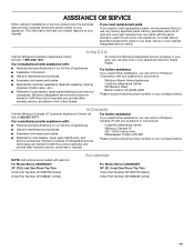
... dealers, repair parts distributors, and service companies. For Model Series UXD8630DY 30" (76.2 cm) One-Piece Top Trim Order Part Number W10387678 (black) Order Part Number W10388421 (white) Accessories For Model Series UXD8636DY 36" (91.4 cm) One-Piece Top Trim Order Part Number W10387679 (black) Order Part Number W10388422 (white) 17 Whirlpool designated service technicians are included with : To locate the Whirlpool designated service company in the United States. In Canada Call the Whirlpool Canada LP Customer eXperience...
... dealers, repair parts distributors, and service companies. For Model Series UXD8630DY 30" (76.2 cm) One-Piece Top Trim Order Part Number W10387678 (black) Order Part Number W10388421 (white) Accessories For Model Series UXD8636DY 36" (91.4 cm) One-Piece Top Trim Order Part Number W10387679 (black) Order Part Number W10388422 (white) 17 Whirlpool designated service technicians are included with : To locate the Whirlpool designated service company in the United States. In Canada Call the Whirlpool Canada LP Customer eXperience...
Installation Guide
Page 18
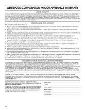
... the customer. Service must provide proof of purchase or installation date for product service if your major appliance is located in -warranty service. Costs associated with electrical or plumbing codes, or use your major appliance, to replace or repair house fuses, or to repair or replace appliance light bulbs, air filters or water filters. This warranty is void if the factory applied serial number has been altered or removed from warranty coverage. 3. LIMITATION OF REMEDIES CUSTOMER...
... the customer. Service must provide proof of purchase or installation date for product service if your major appliance is located in -warranty service. Costs associated with electrical or plumbing codes, or use your major appliance, to replace or repair house fuses, or to repair or replace appliance light bulbs, air filters or water filters. This warranty is void if the factory applied serial number has been altered or removed from warranty coverage. 3. LIMITATION OF REMEDIES CUSTOMER...


