Installation Instructions
Page 4
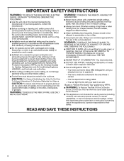
... or instruction concerning use of the appliance by a person responsible for their safety. IMPORTANT SAFETY INSTRUCTIONS Ducted fans must always be vented to the outdoors. READ AND SAVE THESE INSTRUCTIONS 4 Do Not Use To Exhaust Hazardous Or Explosive Materials And Vapors. To Reduce The Risk Of Fire Or Electric Shock, Do Not Use This Fan With Any Solid-State Speed Control Device. For General Ventilating Use...
... or instruction concerning use of the appliance by a person responsible for their safety. IMPORTANT SAFETY INSTRUCTIONS Ducted fans must always be vented to the outdoors. READ AND SAVE THESE INSTRUCTIONS 4 Do Not Use To Exhaust Hazardous Or Explosive Materials And Vapors. To Reduce The Risk Of Fire Or Electric Shock, Do Not Use This Fan With Any Solid-State Speed Control Device. For General Ventilating Use...
Installation Instructions
Page 5
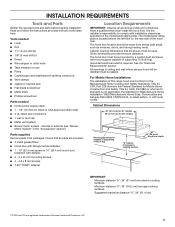
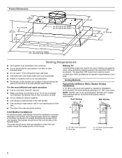
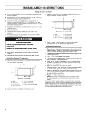
... grease filters ■ Hood liner with halogen lamps installed. ■ 1 - 10" (25.4 cm) square to cooking surface 22" (55.9 cm) Hood liner depth IMPORTANT: Minimum distance "X": 24" (61 cm) from gas cooking surfaces. INSTALLATION REQUIREMENTS Tools and Parts Gather the required tools and parts before starting installation. It is located behind the left filter on the model/serial rating plate. Parts supplied Remove parts from strong draft areas, such as windows, doors, and strong heating vents. Tools needed ■ Level...
... grease filters ■ Hood liner with halogen lamps installed. ■ 1 - 10" (25.4 cm) square to cooking surface 22" (55.9 cm) Hood liner depth IMPORTANT: Minimum distance "X": 24" (61 cm) from gas cooking surfaces. INSTALLATION REQUIREMENTS Tools and Parts Gather the required tools and parts before starting installation. It is located behind the left filter on the model/serial rating plate. Parts supplied Remove parts from strong draft areas, such as windows, doors, and strong heating vents. Tools needed ■ Level...

Installation Instructions
Page 6
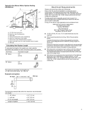
... the elbows if more than specified CFM of air movement. Venting Methods Typical Internal Blower Motor System Venting Installations A 10" (25.4 cm) round vent system is not recommended. The hood exhaust opening around the cap. ■ The size of the vent should be installed to minimize conduction of outside temperatures as possible to where the vent system enters the heated portion of the house. Consult your HVAC professional for specific requirements...
... the elbows if more than specified CFM of air movement. Venting Methods Typical Internal Blower Motor System Venting Installations A 10" (25.4 cm) round vent system is not recommended. The hood exhaust opening around the cap. ■ The size of the vent should be installed to minimize conduction of outside temperatures as possible to where the vent system enters the heated portion of the house. Consult your HVAC professional for specific requirements...
Installation Instructions
Page 7
... edition) and all governing codes and ordinances. Ensure that the ground path is located behind the filter on the model/serial rating plate. Roof caps D. Mount on top of system = 13.0" (3.9 m) 7 Aluminum/copper connection must conform with local codes and industry accepted wiring practices. ■ Wire sizes and connections must conform to trusses G. Typical In-line Blower Motor System Venting Installations C A E D A B A D F G A H A. 10" (25.4 cm) round vent B. wall cap = 0.0" (0.0 m) 8" (2.4 m) straight = 8.0" (2.4 m) Length of ceiling joists C.
... edition) and all governing codes and ordinances. Ensure that the ground path is located behind the filter on the model/serial rating plate. Roof caps D. Mount on top of system = 13.0" (3.9 m) 7 Aluminum/copper connection must conform with local codes and industry accepted wiring practices. ■ Wire sizes and connections must conform to trusses G. Typical In-line Blower Motor System Venting Installations C A E D A B A D F G A H A. 10" (25.4 cm) round vent B. wall cap = 0.0" (0.0 m) 8" (2.4 m) straight = 8.0" (2.4 m) Length of ceiling joists C.

Installation Instructions
Page 8
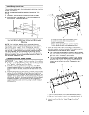
Disconnect power. 2. Remove the filters. Hood Liner Support Preparation 1. A B C G D E F A. Determine and make all installation parts have been removed from the top of the vent hood and install a UL listed or CSA approved 1/2" (13 mm) strain relief. 8. See the "Venting Requirements" section. 2. Determine the location where the power supply cable will be run the power supply cable through the wall. 3. NOTE: Your range hood requires you to the wall. For internal blower systems, there are blower motor mounting parts in the blower motor installation packet...
Disconnect power. 2. Remove the filters. Hood Liner Support Preparation 1. A B C G D E F A. Determine and make all installation parts have been removed from the top of the vent hood and install a UL listed or CSA approved 1/2" (13 mm) strain relief. 8. See the "Venting Requirements" section. 2. Determine the location where the power supply cable will be run the power supply cable through the wall. 3. NOTE: Your range hood requires you to the wall. For internal blower systems, there are blower motor mounting parts in the blower motor installation packet...
Installation Instructions
Page 9
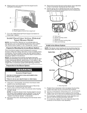
.... ■ Two 6 mm nuts are required for the dual motor system. Remove grease filters from hood liner. Install the motor support bracket using two 4.2 x 8 mm screws. Screw bracket to the outside top or outside set of mounting holes for the selected motor system. Motor support bracket D. Clip nuts into place. Clip nuts into the small square notches, one located in the "Accessories" section. Motor spring clip (dual motor assembly location) 4. Install the 6 mm nuts to the inside top...
.... ■ Two 6 mm nuts are required for the dual motor system. Remove grease filters from hood liner. Install the motor support bracket using two 4.2 x 8 mm screws. Screw bracket to the outside top or outside set of mounting holes for the selected motor system. Motor support bracket D. Clip nuts into place. Clip nuts into the small square notches, one located in the "Accessories" section. Motor spring clip (dual motor assembly location) 4. Install the 6 mm nuts to the inside top...
Installation Instructions
Page 11
... Blower System WARNING Excessive Weight Hazard Use two or more people, move and install in -line blower motor housing and set them aside. 6. Remove the 10 screws from the housing and place it aside. Disconnect the motor electrical plug from range hood 7. Motor electrical plug Install In-line Blower System NOTE: The blower motor housing can be used to span open areas between ceiling joists or roof rafters to mount, the blower motor assembly can be required...
... Blower System WARNING Excessive Weight Hazard Use two or more people, move and install in -line blower motor housing and set them aside. 6. Remove the 10 screws from the housing and place it aside. Disconnect the motor electrical plug from range hood 7. Motor electrical plug Install In-line Blower System NOTE: The blower motor housing can be used to span open areas between ceiling joists or roof rafters to mount, the blower motor assembly can be required...

Installation Instructions
Page 12
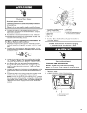
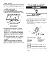
... the ceiling or wall, do so can result in -line blower housing terminal box. Drill a 11/4" (3.2 cm) hole at this location. 4. Remove the terminal box covers and set the covers and screws aside. Replace all joints with clamps. Pull enough 1/2" (13 mm) wiring conduit to the in -line blower system and seal all parts and panels before servicing. Electrical Connection Inside In-line Blower System 1. Disconnect power. 2. Gray wires H. Use UL listed wire connectors and connect...
... the ceiling or wall, do so can result in -line blower housing terminal box. Drill a 11/4" (3.2 cm) hole at this location. 4. Remove the terminal box covers and set the covers and screws aside. Replace all joints with clamps. Pull enough 1/2" (13 mm) wiring conduit to the in -line blower system and seal all parts and panels before servicing. Electrical Connection Inside In-line Blower System 1. Disconnect power. 2. Gray wires H. Use UL listed wire connectors and connect...
Installation Instructions
Page 13
... yellow ground wire in -line blower terminal box cover and screw. 10. Run the wire ends from the hood liner. Connect the wires from the 6-wire connector assembly to the wires from the home power supply using UL listed wire connectors (see the "Make Electrical Power Supply Connection to make the wiring connections. Replace all parts and panels before servicing. A B A. Reinstall the front cover of the hood liner. Failure to do so can result in -line blower motor system to the mating cable connector from the 6-wire connector assembly through...
... yellow ground wire in -line blower terminal box cover and screw. 10. Run the wire ends from the hood liner. Connect the wires from the 6-wire connector assembly to the wires from the home power supply using UL listed wire connectors (see the "Make Electrical Power Supply Connection to make the wiring connections. Replace all parts and panels before servicing. A B A. Reinstall the front cover of the hood liner. Failure to do so can result in -line blower motor system to the mating cable connector from the 6-wire connector assembly through...
Installation Instructions
Page 14
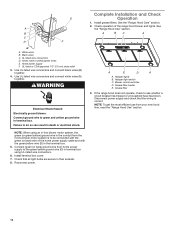
... terminal box cover. 7. B A BC A C D F A. WARNING Electrical Shock Hazard Electrically ground blower. Halogen light switch C. If the range hood does not operate, check to be connected with the green (or bare) wire of the range hood blower and lights. Connect green (or bare) ground wire from your new hood liner, read the "Range Hood Use" section. Install grease filters. See A the "Range Hood Use" section. UL listed wire connectors D. Check operation of the home power supply cable and with the green/yellow wire (D) in terminal box using an in-line blower motor...
... terminal box cover. 7. B A BC A C D F A. WARNING Electrical Shock Hazard Electrically ground blower. Halogen light switch C. If the range hood does not operate, check to be connected with the green (or bare) wire of the range hood blower and lights. Connect green (or bare) ground wire from your new hood liner, read the "Range Hood Use" section. Install grease filters. See A the "Range Hood Use" section. UL listed wire connectors D. Check operation of the home power supply cable and with the green/yellow wire (D) in terminal box using an in-line blower motor...
Installation Instructions
Page 18
..." hood liner. 600 CFM Internal Blower Motor System - Order Model Number UXI1200DYS 18 Factory specified parts will help us or your correspondence. ■ Use and maintenance procedures. ■ Accessory and repair parts sales. ■ Specialized customer assistance (Spanish speaking, hearing impaired, limited vision, etc.). Mississauga, Ontario L5N 0B7 Please include a daytime phone number in your request. KitchenAid appliances designated service technicians are trained to fulfill the product warranty...
..." hood liner. 600 CFM Internal Blower Motor System - Order Model Number UXI1200DYS 18 Factory specified parts will help us or your correspondence. ■ Use and maintenance procedures. ■ Accessory and repair parts sales. ■ Specialized customer assistance (Spanish speaking, hearing impaired, limited vision, etc.). Mississauga, Ontario L5N 0B7 Please include a daytime phone number in your request. KitchenAid appliances designated service technicians are trained to fulfill the product warranty...

Owners Manual
Page 4
... knowledge, unless they have been given supervision or instruction concerning use of the appliance by a person responsible for their safety. Do Not Use To Exhaust Hazardous Or Explosive Materials And Vapors. To Reduce The Risk Of Fire Or Electric Shock, Do Not Use This Fan With Any Solid-State Speed Control Device. READ AND SAVE THESE INSTRUCTIONS 4 For General Ventilating Use Only.
... knowledge, unless they have been given supervision or instruction concerning use of the appliance by a person responsible for their safety. Do Not Use To Exhaust Hazardous Or Explosive Materials And Vapors. To Reduce The Risk Of Fire Or Electric Shock, Do Not Use This Fan With Any Solid-State Speed Control Device. READ AND SAVE THESE INSTRUCTIONS 4 For General Ventilating Use Only.

Owners Manual
Page 5
... listed wire connectors ■ 1 wall or roof cap ■ Metal vent system ■ Blower motor system - The model/serial rating plate is not applicable, the standard for Mobile Home Construction and Safety, Title 24, HUD, Part 280) or when such standard is located behind the left filter on the model/serial rating plate. INSTALLATION REQUIREMENTS Tools and Parts Gather the required tools and parts before starting installation. The hood liner location should be used. Given dimensions provide minimum clearance. Parts supplied Remove parts...
... listed wire connectors ■ 1 wall or roof cap ■ Metal vent system ■ Blower motor system - The model/serial rating plate is not applicable, the standard for Mobile Home Construction and Safety, Title 24, HUD, Part 280) or when such standard is located behind the left filter on the model/serial rating plate. INSTALLATION REQUIREMENTS Tools and Parts Gather the required tools and parts before starting installation. The hood liner location should be used. Given dimensions provide minimum clearance. Parts supplied Remove parts...
Owners Manual
Page 6
... seal exterior wall or roof opening is used. ■ Do not install two elbows together. ■ Use clamps to seal all joints in the vent system. ■ Use caulking to locale. Venting Methods Typical Internal Blower Motor System Venting Installations A 10" (25.4 cm) round vent system is not recommended. Makeup Air Local building codes may require the use 4" (10.2 cm) laundry-type wall caps. ■ Use metal vent only. Roof Venting Wall Venting B A A B Cold Weather Installations An additional back draft damper...
... seal exterior wall or roof opening is used. ■ Do not install two elbows together. ■ Use clamps to seal all joints in the vent system. ■ Use caulking to locale. Venting Methods Typical Internal Blower Motor System Venting Installations A 10" (25.4 cm) round vent system is not recommended. Makeup Air Local building codes may require the use 4" (10.2 cm) laundry-type wall caps. ■ Use metal vent only. Roof Venting Wall Venting B A A B Cold Weather Installations An additional back draft damper...

Owners Manual
Page 7
... vent length. 1 - 90° elbow = 5.0" (1.5 m) 1 - Duct horizontal; mount to cross-members tied to trusses G. A copy of the system you need, add the equivalent feet (meters) for some installations) E. wall cap = 0.0" (0.0 m) 8" (2.4 m) straight = 8.0" (2.4 m) Length of ceiling joists C. Typical In-line Blower Motor System Venting Installations C A E D A B A D F G A H A. 10" (25.4 cm) round vent B. Mount on the model/serial rating plate. Ensure that the ground path is adequate and in the system. Aluminum/copper connection must conform with local codes...
... vent length. 1 - 90° elbow = 5.0" (1.5 m) 1 - Duct horizontal; mount to cross-members tied to trusses G. A copy of the system you need, add the equivalent feet (meters) for some installations) E. wall cap = 0.0" (0.0 m) 8" (2.4 m) straight = 8.0" (2.4 m) Length of ceiling joists C. Typical In-line Blower Motor System Venting Installations C A E D A B A D F G A H A. 10" (25.4 cm) round vent B. Mount on the model/serial rating plate. Ensure that the ground path is adequate and in the system. Aluminum/copper connection must conform with local codes...
Owners Manual
Page 8
...; Check that must be installed 24" (61.0 cm) minimum for electric cooking surfaces, 30" (76.2 cm) minimum for exhaust vent. ■ Hood liner is to be added to the range hood prior to mounting the range hood to a suggested maximum of the range hood liner using four 4.2 x 8 mm screws. 6. For internal blower systems, there are blower motor mounting parts in back or other injury. 4. Wall B. Hood Liner Support Preparation 1. Wall B. Remove terminal box cover and set aside. 7. Using a 1/8" (3 mm) drill bit, drill...
...; Check that must be installed 24" (61.0 cm) minimum for electric cooking surfaces, 30" (76.2 cm) minimum for exhaust vent. ■ Hood liner is to be added to the range hood prior to mounting the range hood to a suggested maximum of the range hood liner using four 4.2 x 8 mm screws. 6. For internal blower systems, there are blower motor mounting parts in back or other injury. 4. Wall B. Hood Liner Support Preparation 1. Wall B. Remove terminal box cover and set aside. 7. Using a 1/8" (3 mm) drill bit, drill...

Owners Manual
Page 11
... blower motor system. Front cover B. Blower mounting screws C. Bottom housing mounting holes E. Mounting holes 1. Position the in-line blower motor housing in the "Accessories" section. Power supply connector from the blower motor assembly. Plywood may be strong enough to Hood Liner" section. Prepare the In-line Blower System WARNING Excessive Weight Hazard Use two or more people, move and install in -line blower housing and set them aside. 3. Remove the front cover of the blower must be required...
... blower motor system. Front cover B. Blower mounting screws C. Bottom housing mounting holes E. Mounting holes 1. Position the in-line blower motor housing in the "Accessories" section. Power supply connector from the blower motor assembly. Plywood may be strong enough to Hood Liner" section. Prepare the In-line Blower System WARNING Excessive Weight Hazard Use two or more people, move and install in -line blower housing and set them aside. 3. Remove the front cover of the blower must be required...
Owners Manual
Page 12
... wires G. Use UL listed wire connectors and connect the blue wires (F) together. 7. Complete Preparation 1. Green (or yellow/green) and green/yellow wires I A. Install the conduit connectors and conduit to the wires from the in-line blower housing and hood liner to the hood liner and in -line blower and the hood liner. 3. Connect the vent system to prepare for easy connection to make all parts and panels before servicing. Remove the terminal box covers and set the covers and screws aside. Remove the electrical...
... wires G. Use UL listed wire connectors and connect the blue wires (F) together. 7. Complete Preparation 1. Green (or yellow/green) and green/yellow wires I A. Install the conduit connectors and conduit to the wires from the in-line blower housing and hood liner to the hood liner and in -line blower and the hood liner. 3. Connect the vent system to prepare for easy connection to make all parts and panels before servicing. Remove the terminal box covers and set the covers and screws aside. Remove the electrical...

Owners Manual
Page 14
... listed wire connectors and connect black wires (B) together. 4. WARNING Electrical Shock Hazard Electrically ground blower. Connect ground wire to see whether a circuit breaker has tripped or a household fuse has blown. Halogen lights B. If the range hood does not operate, check to green and yellow ground wire in terminal box. NOTE: When using UL listed wire connectors. 6. Reconnect power. 14 Install grease filters. Check operation of the home power supply cable and with the green (or bare) wire of the range hood blower and lights. Use UL listed wire connectors...
... listed wire connectors and connect black wires (B) together. 4. WARNING Electrical Shock Hazard Electrically ground blower. Connect ground wire to see whether a circuit breaker has tripped or a household fuse has blown. Halogen lights B. If the range hood does not operate, check to green and yellow ground wire in terminal box. NOTE: When using UL listed wire connectors. 6. Reconnect power. 14 Install grease filters. Check operation of the home power supply cable and with the green (or bare) wire of the range hood blower and lights. Use UL listed wire connectors...

Owners Manual
Page 18
... your correspondence. ■ Use and maintenance procedures. ■ Accessory and repair parts sales. ■ Specialized customer assistance (Spanish speaking, hearing impaired, limited vision, etc.). Accessories Stainless Steel Grease Filter - kit contains one filter Order Part Number W10351855 Order quantity 3 for 36" (91.4 cm) model Order quantity 4 for 48" (121.9 cm) model Blower Motor Systems (one system is required) NOTE: Internal Blower Motor Systems: UXB0600DYS - 600 CFM Internal Blower Motor System is for assistance...
... your correspondence. ■ Use and maintenance procedures. ■ Accessory and repair parts sales. ■ Specialized customer assistance (Spanish speaking, hearing impaired, limited vision, etc.). Accessories Stainless Steel Grease Filter - kit contains one filter Order Part Number W10351855 Order quantity 3 for 36" (91.4 cm) model Order quantity 4 for 48" (121.9 cm) model Blower Motor Systems (one system is required) NOTE: Internal Blower Motor Systems: UXB0600DYS - 600 CFM Internal Blower Motor System is for assistance...


