Use & Care Guide
Page 1
... manual and on the front facing of burns, electric shock, fire, injury to persons, or exposure to excessive microwave energy: ■ Install or locate the microwave oven only in accordance with the provided Installation Instructions. ■ Read all safety messages. IMPORTANT SAFETY INSTRUCTIONS When using the microwave oven. ■ Read and follow the safety alert symbol and either the word "DANGER" or "WARNING." User Guide Microwave Hood Combination...
... manual and on the front facing of burns, electric shock, fire, injury to persons, or exposure to excessive microwave energy: ■ Install or locate the microwave oven only in accordance with the provided Installation Instructions. ■ Read all safety messages. IMPORTANT SAFETY INSTRUCTIONS When using the microwave oven. ■ Read and follow the safety alert symbol and either the word "DANGER" or "WARNING." User Guide Microwave Hood Combination...

Use & Care Guide
Page 2
... the hood, turn oven off, and disconnect the power cord, or shut off power at the fuse or circuit breaker panel. ■ Use care when cleaning the vent-hood filter. Do not use . ■ As with maximum width of oven is damaged. State of California Proposition 65 Warnings: WARNING: This product contains one or more chemicals known to the State of table or counter. ■ See door surface cleaning instructions in the microwave oven. Carefully...
... the hood, turn oven off, and disconnect the power cord, or shut off power at the fuse or circuit breaker panel. ■ Use care when cleaning the vent-hood filter. Do not use . ■ As with maximum width of oven is damaged. State of California Proposition 65 Warnings: WARNING: This product contains one or more chemicals known to the State of table or counter. ■ See door surface cleaning instructions in the microwave oven. Carefully...

Use & Care Guide
Page 3
... the power supply cord is equipped with a cord having a grounding wire with a grounding plug. Recommended: ■ A time-delay fuse or time-delay circuit breaker. ■ A separate circuit serving only this microwave oven. Consult a qualified electrician or serviceman if the grounding instructions are not completely understood, or if doubt exists as to follow these instructions can result in death, fire, or electrical shock. Do not remove...
... the power supply cord is equipped with a cord having a grounding wire with a grounding plug. Recommended: ■ A time-delay fuse or time-delay circuit breaker. ■ A separate circuit serving only this microwave oven. Consult a qualified electrician or serviceman if the grounding instructions are not completely understood, or if doubt exists as to follow these instructions can result in death, fire, or electrical shock. Do not remove...

Use & Care Guide
Page 4
... activate reset. Touch Options or Setup control to unlock control. Touch the Start control to run for about 3 seconds until 2 tones sound and padlock icon appears in microwave oven with A.M. Options or Setup Vent Timer, Light Timer, Filter Reset, Sound On/Off, Scroll Speed, Demo Mode and Language (on the magnetron. Filter Reset Reset the filter status after 30 minutes). Demo Mode Activate to reach the "Demo Mode" submenu, and activate or deactivate Demo Mode. Program 1 minute of -function signals) may be changed. Light Timer Set the cooktop light...
... activate reset. Touch Options or Setup control to unlock control. Touch the Start control to run for about 3 seconds until 2 tones sound and padlock icon appears in microwave oven with A.M. Options or Setup Vent Timer, Light Timer, Filter Reset, Sound On/Off, Scroll Speed, Demo Mode and Language (on the magnetron. Filter Reset Reset the filter status after 30 minutes). Demo Mode Activate to reach the "Demo Mode" submenu, and activate or deactivate Demo Mode. Program 1 minute of -function signals) may be changed. Light Timer Set the cooktop light...

Use & Care Guide
Page 5
... Touch COOK TIME, touch number pads to enter time, touch COOK POWER (if not 100%), touch number pads to soil buildup, keep cavity, microwave inlet cover, cooking rack supports, and area where the door touches the frame clean. If programming additional stages, enter the cook time and cook power of each before touching the Start control. Preset Defrosting Unwrap food. The charcoal filter cannot be cleaned, and should be replaced about every 6 months, or as prompted by filter status indicator. Remove bulb cover screw, and open the bulb cover. Close bulb cover, replace vent grille...
... Touch COOK TIME, touch number pads to enter time, touch COOK POWER (if not 100%), touch number pads to soil buildup, keep cavity, microwave inlet cover, cooking rack supports, and area where the door touches the frame clean. If programming additional stages, enter the cook time and cook power of each before touching the Start control. Preset Defrosting Unwrap food. The charcoal filter cannot be cleaned, and should be replaced about every 6 months, or as prompted by filter status indicator. Remove bulb cover screw, and open the bulb cover. Close bulb cover, replace vent grille...

Use & Care Guide
Page 6
... phone number in this manual and scan the code with any questions or concerns at 100% cooking power. Make sure Demo Mode (on during microwave oven operation. Open and close door. Contact us by a number is normal. Move the receiver away from the vent fan, automatically comes on some models, if a packaging spacer is attached to avoid unintended starting of available parts and supplies which is a list of the microwave oven...
... phone number in this manual and scan the code with any questions or concerns at 100% cooking power. Make sure Demo Mode (on during microwave oven operation. Open and close door. Contact us by a number is normal. Move the receiver away from the vent fan, automatically comes on some models, if a packaging spacer is attached to avoid unintended starting of available parts and supplies which is a list of the microwave oven...

Use & Care Guide
Page 7
... the Use and Care Guide, scan the QR code on the duration of implied warranties of household electrical or plumbing (i.e. In the event of this major appliance other rights that existed when this limited warranty. 1. house wiring, fuses or water inlet hoses). 4. trim, decorative panels, flooring, cabinetry, islands, countertops, drywall, etc.) that comes with products not approved by Whirlpool. 7. Service or parts for service or repair of product replacement...
... the Use and Care Guide, scan the QR code on the duration of implied warranties of household electrical or plumbing (i.e. In the event of this major appliance other rights that existed when this limited warranty. 1. house wiring, fuses or water inlet hoses). 4. trim, decorative panels, flooring, cabinetry, islands, countertops, drywall, etc.) that comes with products not approved by Whirlpool. 7. Service or parts for service or repair of product replacement...
Warranty Information
Page 1
... with servicing, removal or replacement of the original unit's warranty period. trim, decorative panels, flooring, cabinetry, islands, countertops, drywall, etc.) that comes with the product, Whirlpool Corporation or Whirlpool Canada LP (hereafter "Whirlpool") will be borne by unauthorized service, alteration or modification of inaccessible appliances or built-in -home repair. 12. Please take a few minutes to review the Troubleshooting or Problem Solver section of the Use and Care Guide...
... with servicing, removal or replacement of the original unit's warranty period. trim, decorative panels, flooring, cabinetry, islands, countertops, drywall, etc.) that comes with the product, Whirlpool Corporation or Whirlpool Canada LP (hereafter "Whirlpool") will be borne by unauthorized service, alteration or modification of inaccessible appliances or built-in -home repair. 12. Please take a few minutes to review the Troubleshooting or Problem Solver section of the Use and Care Guide...
Installation Guide
Page 1
... follow instructions. Table of Contents MICROWAVE HOOD COMBINATION SAFETY 1 INSTALLATION REQUIREMENTS 2 Tools and Parts 2 Remove Cardboard Template 2 Location Requirements 2 Product Dimensions 3 Electrical Requirements 3 INSTALLATION INSTRUCTIONS 4 Remove Mounting Plate 4 Rotate Blower Motor 4 Locate Wall Stud(s 6 Mark Rear Wall 7 Drill Holes in Rear Wall 7 Attach Mounting Plate to reduce the chance of your particular model may differ slightly from the illustration in this manual and on your appliance. See "Installation Requirements" section for use above electric or...
... follow instructions. Table of Contents MICROWAVE HOOD COMBINATION SAFETY 1 INSTALLATION REQUIREMENTS 2 Tools and Parts 2 Remove Cardboard Template 2 Location Requirements 2 Product Dimensions 3 Electrical Requirements 3 INSTALLATION INSTRUCTIONS 4 Remove Mounting Plate 4 Rotate Blower Motor 4 Locate Wall Stud(s 6 Mark Rear Wall 7 Drill Holes in Rear Wall 7 Attach Mounting Plate to reduce the chance of your particular model may differ slightly from the illustration in this manual and on your appliance. See "Installation Requirements" section for use above electric or...

Installation Guide
Page 2
..."Mark Rear Wall" part of packaging) Aluminum grease filters Charcoal filters (Depending on model, charcoal filters may be combined. Sheet metal screws (2) G. Materials needed ■ Standard fittings for 1/4" x 2" lag screws ■ 1½" (3.8 cm) diam. Location Requirements Check the opening . ■ Support for wall or roof venting) Not Shown: Upper cabinet template Mounting plate (attached to back of microwave oven) Cardboard template (part of installation. Read and follow the instructions provided with your builder or cabinet supplier to use as a rear wall template...
..."Mark Rear Wall" part of packaging) Aluminum grease filters Charcoal filters (Depending on model, charcoal filters may be combined. Sheet metal screws (2) G. Materials needed ■ Standard fittings for 1/4" x 2" lag screws ■ 1½" (3.8 cm) diam. Location Requirements Check the opening . ■ Support for wall or roof venting) Not Shown: Upper cabinet template Mounting plate (attached to back of microwave oven) Cardboard template (part of installation. Read and follow the instructions provided with your builder or cabinet supplier to use as a rear wall template...

Installation Guide
Page 3
... depending on door design. Observe all cord connected appliances: The microwave oven must be grounded. Recommended: ■ A time-delay fuse or time-delay circuit breaker. ■ A separate circuit serving only this microwave oven. Do not use an adapter. SAVE THESE INSTRUCTIONS 3 Do not use an extension cord. or 20-amp electrical supply with a grounding plug. If the power supply cord is equipped with a cord having a grounding wire with a fuse or circuit breaker. Installation Dimensions NOTE...
... depending on door design. Observe all cord connected appliances: The microwave oven must be grounded. Recommended: ■ A time-delay fuse or time-delay circuit breaker. ■ A separate circuit serving only this microwave oven. Do not use an adapter. SAVE THESE INSTRUCTIONS 3 Do not use an extension cord. or 20-amp electrical supply with a grounding plug. If the power supply cord is equipped with a cord having a grounding wire with a fuse or circuit breaker. Installation Dimensions NOTE...

Installation Guide
Page 4
Remove 2 screws attaching blower motor to the work surface, cover the work surface. 1. Lift blower motor out of the microwave oven and lift up. NOTE: Skip this section if you are using recirculation installation. Wall Venting Installation Only 1. Screws B. Slide damper plate toward the front of microwave oven. A B A. Keep damper plate and screws together and set it aside. 3. A. INSTALLATION INSTRUCTIONS Remove Mounting Plate Depending on your model, the mounting plate may be in the foam packaging, or it may be attached to...
Remove 2 screws attaching blower motor to the work surface, cover the work surface. 1. Lift blower motor out of the microwave oven and lift up. NOTE: Skip this section if you are using recirculation installation. Wall Venting Installation Only 1. Screws B. Slide damper plate toward the front of microwave oven. A B A. Keep damper plate and screws together and set it aside. 3. A. INSTALLATION INSTRUCTIONS Remove Mounting Plate Depending on your model, the mounting plate may be in the foam packaging, or it may be attached to...

Installation Guide
Page 5
...facing the back of microwave oven. Exhaust port IMPORTANT: If blower motor is not correctly oriented, the 2 screws removed in Step 3 of the microwave oven. Repeat Step 2 from "Wall Venting Installation Only." 5. A C D A. Slots 8. Damper plate B. Make sure damper plate tabs are inserted into the slots in Step 1. Reattach damper plate. A B D A. Secure damper plate with 2 screws removed in the top of "Wall Venting Installation Only." A. Roof Venting Installation Only 1. Screws C. Repeat Step 4 from "Wall Venting Installation Only." 3. Securely tighten...
...facing the back of microwave oven. Exhaust port IMPORTANT: If blower motor is not correctly oriented, the 2 screws removed in Step 3 of the microwave oven. Repeat Step 2 from "Wall Venting Installation Only." 5. A C D A. Slots 8. Damper plate B. Make sure damper plate tabs are inserted into the slots in Step 1. Reattach damper plate. A B D A. Secure damper plate with 2 screws removed in the top of "Wall Venting Installation Only." A. Roof Venting Installation Only 1. Screws C. Repeat Step 4 from "Wall Venting Installation Only." 3. Securely tighten...

Installation Guide
Page 6
... Figure 4 B D B A A,D A,D A,D E E E E C C C C F F A. Cabinet opening vertical centerline C. Holes for lag screws E. Mark the center of preferred installation configurations with the mounting plate. Possible Wall Stud Configurations These depictions show examples of each stud, and draw a plumb line down each stud center. Mounting plate center markers 6 End holes (on mounting plate) B. Support tabs F. Using a stud finder, locate the edges of the vertical centerline (see "Mark Rear Wall" section), only...
... Figure 4 B D B A A,D A,D A,D E E E E C C C C F F A. Cabinet opening vertical centerline C. Holes for lag screws E. Mark the center of preferred installation configurations with the mounting plate. Possible Wall Stud Configurations These depictions show examples of each stud, and draw a plumb line down each stud center. Mounting plate center markers 6 End holes (on mounting plate) B. Support tabs F. Using a stud finder, locate the edges of the vertical centerline (see "Mark Rear Wall" section), only...

Installation Guide
Page 7
... hole locations. 7. Holding the mounting plate in "Locate Wall Stud(s)" section), align the mounting plate center markers to the centerline on a level line with the dimensions described in Step 2 of the cardboard template is aligned to the wall stud centerline(s). With the support tabs facing forward (see illustrations in place, find and clearly mark the vertical centerline of cabinet. Using a keyhole saw, cut out the venting cutout area...
... hole locations. 7. Holding the mounting plate in "Locate Wall Stud(s)" section), align the mounting plate center markers to the centerline on a level line with the dimensions described in Step 2 of the cardboard template is aligned to the wall stud centerline(s). With the support tabs facing forward (see illustrations in place, find and clearly mark the vertical centerline of cabinet. Using a keyhole saw, cut out the venting cutout area...

Installation Guide
Page 8
... the template is level. 7. Check alignment of the mounting plate. Start a toggle nut on the rear wall. Leave enough space for the toggle nut to go through the drywall, and finger tighten the bolts to make sure toggle nut has opened against the bottom of the upper cabinet, and attach with toggle nut through both ends. 1. Disconnect power to use as guides...
... the template is level. 7. Check alignment of the mounting plate. Start a toggle nut on the rear wall. Leave enough space for the toggle nut to go through the drywall, and finger tighten the bolts to make sure toggle nut has opened against the bottom of the upper cabinet, and attach with toggle nut through both ends. 1. Disconnect power to use as guides...

Installation Guide
Page 9
... Microwave Oven WARNING Excessive Weight Hazard Use two or more people, lift microwave oven and hang it on Upper Cabinet Template. 8. IMPORTANT: The control side of the shaded rectangular area "F" on support tabs at one corner of the microwave oven is at the top, and the damper blade opens away from the microwave oven. Handle the microwave oven gently. 1. A B A. NOTE: If venting through the power supply cord hole in the wall cutout. 6. Position the damper assembly...
... Microwave Oven WARNING Excessive Weight Hazard Use two or more people, lift microwave oven and hang it on Upper Cabinet Template. 8. IMPORTANT: The control side of the shaded rectangular area "F" on support tabs at one corner of the microwave oven is at the top, and the damper blade opens away from the microwave oven. Handle the microwave oven gently. 1. A B A. NOTE: If venting through the power supply cord hole in the wall cutout. 6. Position the damper assembly...

Installation Guide
Page 10
... mounting plate, and set aside on the turntable, and programming a cook time of the microwave oven. Refer to damper assembly. Then secure with at 100% power. A B C D E F A. Raised tabs B. Damper assembly C. Do not remove ground prong. Check the operation of microwave oven by operating the vent fan. 5. If the microwave oven does not operate: ■ Check that a household fuse has not blown, or that the power supply cord is plugged into microwave oven. Tighten bolts until there is now complete. Install filters. WARNING A. Replace...
... mounting plate, and set aside on the turntable, and programming a cook time of the microwave oven. Refer to damper assembly. Then secure with at 100% power. A B C D E F A. Raised tabs B. Damper assembly C. Do not remove ground prong. Check the operation of microwave oven by operating the vent fan. 5. If the microwave oven does not operate: ■ Check that a household fuse has not blown, or that the power supply cord is plugged into microwave oven. Tighten bolts until there is now complete. Install filters. WARNING A. Replace...

Installation Guide
Page 12
... (0.6 m) + 6 ft (1.8 m) straight = 8 ft (2.4 m) If the existing vent is located behind the door. ■ Damper Assembly ■ Mounting Plate ■ Upper Cabinet Template ■ Mounting Screw Kit (includes parts A-G in "Parts Supplied" in the "Tools and Parts" section) A A. Both numbers can be replaced, call us at our toll free number listed in the User Guide. Accessories Filler Panel Kits are available from sticking. Following is 3" (7.6 cm) wide. Filler panels Filler Panel Kit Number 8171336 8171337 8171338 8171339 99403 White...
... (0.6 m) + 6 ft (1.8 m) straight = 8 ft (2.4 m) If the existing vent is located behind the door. ■ Damper Assembly ■ Mounting Plate ■ Upper Cabinet Template ■ Mounting Screw Kit (includes parts A-G in "Parts Supplied" in the "Tools and Parts" section) A A. Both numbers can be replaced, call us at our toll free number listed in the User Guide. Accessories Filler Panel Kits are available from sticking. Following is 3" (7.6 cm) wide. Filler panels Filler Panel Kit Number 8171336 8171337 8171338 8171339 99403 White...
Dimension Guide
Page 1
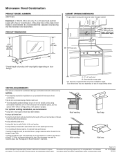
....0 cm) *Overall depth of range/cooktop below. q We do not recommend using recirculation installation. Instructions packed with a fuse or circuit breaker. Microwave Hood Combination PRODUCT MODEL NUMBERS UMV1160C Electrical: A 120-Volt, 60-Hz, AC-only, 15- Do not vent exhaust air into concealed spaces, such as spaces within the wall for optimal hood performance If venting through the roof, and rectangular to open fully. Exact dimensions may vary depending on type...
....0 cm) *Overall depth of range/cooktop below. q We do not recommend using recirculation installation. Instructions packed with a fuse or circuit breaker. Microwave Hood Combination PRODUCT MODEL NUMBERS UMV1160C Electrical: A 120-Volt, 60-Hz, AC-only, 15- Do not vent exhaust air into concealed spaces, such as spaces within the wall for optimal hood performance If venting through the roof, and rectangular to open fully. Exact dimensions may vary depending on type...


