
Dimension Guide
Page 1
... RF110AXS RF111PXS RF114PXS RF212PXS RF263LXT RF264LXS Electrical: Range must be connected directly to the circuit breaker box (or fused disconnect) through the neutral, use with not less than 1/4" (6.4 mm) flame retardant millboard covered with ranges. The model/serial number rating plate is recommended. A circuit breaker is located behind the control panel or on the oven frame behind storage drawer panel) *Range can be connected to change without notice. The range can be raised approximately 1" (2.5 cm...
... RF110AXS RF111PXS RF114PXS RF212PXS RF263LXT RF264LXS Electrical: Range must be connected directly to the circuit breaker box (or fused disconnect) through the neutral, use with not less than 1/4" (6.4 mm) flame retardant millboard covered with ranges. The model/serial number rating plate is recommended. A circuit breaker is located behind the control panel or on the oven frame behind storage drawer panel) *Range can be connected to change without notice. The range can be raised approximately 1" (2.5 cm...

Installation Instructions
Page 1
U.S.A. W10252706B U.S.A. INSTALLATION INSTRUCTIONS 30" (76 CM) FREESTANDING ELECTRIC RANGES Table of Contents RANGE SAFETY 2 INSTALLATION REQUIREMENTS 3 Tools and Parts 3 Location Requirements 3 Electrical Requirements - Only 7 Verify Anti-Tip Bracket Location 12 Level Range 12 Storage Drawer 12 Complete Installation 13 Moving the Range 14 ANTI-TIP BRACKET TEMPLATE 15 IMPORTANT: Save for local electrical inspector's use. Only 4 INSTALLATION INSTRUCTIONS 6 Unpack Range 6 Install Anti-Tip Bracket 6 Electrical Connection -
U.S.A. W10252706B U.S.A. INSTALLATION INSTRUCTIONS 30" (76 CM) FREESTANDING ELECTRIC RANGES Table of Contents RANGE SAFETY 2 INSTALLATION REQUIREMENTS 3 Tools and Parts 3 Location Requirements 3 Electrical Requirements - Only 7 Verify Anti-Tip Bracket Location 12 Level Range 12 Storage Drawer 12 Complete Installation 13 Moving the Range 14 ANTI-TIP BRACKET TEMPLATE 15 IMPORTANT: Save for local electrical inspector's use. Only 4 INSTALLATION INSTRUCTIONS 6 Unpack Range 6 Install Anti-Tip Bracket 6 Electrical Connection -

Installation Instructions
Page 2
... You can be killed or seriously injured if you don't immediately follow these instructions can kill or hurt you and others are not followed. Reconnect the anti-tip bracket, if the range is the safety alert symbol. RANGE SAFETY Your safety and the safety of injury, and tell you what the ... symbol and either the word "DANGER" or "WARNING." WARNING Tip Over Hazard A child or adult can be killed or seriously injured if you to rear range foot. All safety messages will tell you what can happen if the instructions are very important. Always read and obey all safety messages....
... You can be killed or seriously injured if you don't immediately follow these instructions can kill or hurt you and others are not followed. Reconnect the anti-tip bracket, if the range is the safety alert symbol. RANGE SAFETY Your safety and the safety of injury, and tell you what the ... symbol and either the word "DANGER" or "WARNING." WARNING Tip Over Hazard A child or adult can be killed or seriously injured if you to rear range foot. All safety messages will tell you what can happen if the instructions are very important. Always read and obey all safety messages....

Installation Instructions
Page 3
... located for convenient use the Standard for use with nominal 1³⁄₈" (3.5 cm) diameter connection opening dimensions that the materials used . Check existing electrical supply. The model/serial rating plate is required. To install the antitip bracket shipped with any tools listed here. Additional Installation Requirements The installation of burns or fire by reaching over heated surface units, cabinet storage space located above . ■ Four-wire power supply cord or cable must be revised. See "Electrical Requirements...
... located for convenient use the Standard for use with nominal 1³⁄₈" (3.5 cm) diameter connection opening dimensions that the materials used . Check existing electrical supply. The model/serial rating plate is required. To install the antitip bracket shipped with any tools listed here. Additional Installation Requirements The installation of burns or fire by reaching over heated surface units, cabinet storage space located above . ■ Four-wire power supply cord or cable must be revised. See "Electrical Requirements...

Installation Instructions
Page 4
....0 cm) max. Electrical Requirements - Only If codes permit and a separate ground wire is covered by adjusting the leveling legs. depth with handle B. 46⁷⁄₈" (119.1 cm) overall height (max.) with leveling legs screwed all the way in* C. 36" (91.4 cm) cooktop height (max.) with local codes. Cabinet Dimensions Cabinet opening dimensions shown are adequate and in conformance with the National Electrical Code, ANSI/ NFPA...
....0 cm) max. Electrical Requirements - Only If codes permit and a separate ground wire is covered by adjusting the leveling legs. depth with handle B. 46⁷⁄₈" (119.1 cm) overall height (max.) with leveling legs screwed all the way in* C. 36" (91.4 cm) cooktop height (max.) with local codes. Cabinet Dimensions Cabinet opening dimensions shown are adequate and in conformance with the National Electrical Code, ANSI/ NFPA...

Installation Instructions
Page 5
... the control panel or on the appliance end must be provided at the point the power supply cord enters the appliance. This uses a 3-wire receptacle of the 4-wire power supply cord is less than the total connected load listed on the model/serial number rating plate. Use a 3-wire, UL listed, 40- Range Rating* 120/240 Volts 8.8 - 16.5 KW 16.6 - 22.5 KW 120/208 Volts 7.8 - 12.5 KW 12.6 - 18.5 KW Specified Rating of Power Supply Cord Kit and...
... the control panel or on the appliance end must be provided at the point the power supply cord enters the appliance. This uses a 3-wire receptacle of the 4-wire power supply cord is less than the total connected load listed on the model/serial number rating plate. Use a 3-wire, UL listed, 40- Range Rating* 120/240 Volts 8.8 - 16.5 KW 16.6 - 22.5 KW 120/208 Volts 7.8 - 12.5 KW 12.6 - 18.5 KW Specified Rating of Power Supply Cord Kit and...

Installation Instructions
Page 6
... On Ranges Equipped with Warming Drawers: On ranges equipped with a warming drawer, the rear legs cannot be killed. A. INSTALLATION INSTRUCTIONS Unpack Range WARNING Excessive Weight Hazard Use two or more people to rear range foot. Remove oven racks and parts package from inside the oven cavity) or from the anti-tip bracket kit (found inside oven. 3. Connect anti-tip bracket to move and install range. Failure to lower the rear leveling legs one -half turn. Place template on the floor in cabinet opening...
... On Ranges Equipped with Warming Drawers: On ranges equipped with a warming drawer, the rear legs cannot be killed. A. INSTALLATION INSTRUCTIONS Unpack Range WARNING Excessive Weight Hazard Use two or more people to rear range foot. Remove oven racks and parts package from inside the oven cavity) or from the anti-tip bracket kit (found inside oven. 3. Connect anti-tip bracket to move and install range. Failure to lower the rear leveling legs one -half turn. Place template on the floor in cabinet opening...

Installation Instructions
Page 7
.... Plug into holes with a hammer. Hex-head screws 7 Align anti-tip bracket holes with screws provided. Longer screws are available from floor. 6. Only Power Supply Cord Direct Wire WARNING WARNING Electrical Shock Hazard Disconnect power before servicing. Electrical Shock Hazard Disconnect power before servicing. Electrically ground range. Remove plastic tag holding three 10-32 hex nuts from range. 3. Tap plastic anchors into a grounded outlet. Depending on the bracket template. A B C A. Electrical Connection - Pull cover...
.... Plug into holes with a hammer. Hex-head screws 7 Align anti-tip bracket holes with screws provided. Longer screws are available from floor. 6. Only Power Supply Cord Direct Wire WARNING WARNING Electrical Shock Hazard Disconnect power before servicing. Electrical Shock Hazard Disconnect power before servicing. Electrically ground range. Remove plastic tag holding three 10-32 hex nuts from range. 3. Tap plastic anchors into a grounded outlet. Depending on the bracket template. A B C A. Electrical Connection - Pull cover...

Installation Instructions
Page 8
...; Tighten strain relief screw against the flexible conduit. 3-wire direct ³⁄₈" (1.0 cm) A circuit breaker 3-wire connection: box or fused Direct wire disconnect 3" (7.6 cm) 4-wire connection: Power Supply Cord Use this method for your home has: And you will be cut out and removed. A B A. Part of the ground-link under the screw. 8 Complete installation following instructions for : ■ New branch-circuit installations (1996 NEC) ■ Mobile homes ■ Recreational...
...; Tighten strain relief screw against the flexible conduit. 3-wire direct ³⁄₈" (1.0 cm) A circuit breaker 3-wire connection: box or fused Direct wire disconnect 3" (7.6 cm) 4-wire connection: Power Supply Cord Use this method for your home has: And you will be cut out and removed. A B A. Part of the ground-link under the screw. 8 Complete installation following instructions for : ■ New branch-circuit installations (1996 NEC) ■ Mobile homes ■ Recreational...

Installation Instructions
Page 10
... of terminal lugs. The ground wire must be cut out and removed. Strip outer covering back 3" (7.6 cm) to the terminal block. Bare (green) ground wire E. Neutral (white) wire G. Line 1 (black) wire 4. Line 1 (black) wire Bare Wire Torque Specifications Attaching terminal lugs to the fuse disconnect or circuit breaker box. Cord/conduit plate D. Terminal lug B. Part of metal ground strap must be connected directly to the terminal block - 20...
... of terminal lugs. The ground wire must be cut out and removed. Strip outer covering back 3" (7.6 cm) to the terminal block. Bare (green) ground wire E. Neutral (white) wire G. Line 1 (black) wire 4. Line 1 (black) wire Bare Wire Torque Specifications Attaching terminal lugs to the fuse disconnect or circuit breaker box. Cord/conduit plate D. Terminal lug B. Part of metal ground strap must be connected directly to the terminal block - 20...

Installation Instructions
Page 12
... Drawer" section. Place level on some models). A. Depress the drawer clip by removing the warming drawer. On models with a storage drawer, remove storage drawer. Pull the storage drawer forward to back. 3. Replace the storage drawer (on rack and check levelness of the drawer clip. 2. view from outside the range. Gently pull forward on the outside of range, first side to view the rear foot from the anti-tip bracket. Repeat steps 2, 3, and 4, for satisfactory baking performance...
... Drawer" section. Place level on some models). A. Depress the drawer clip by removing the warming drawer. On models with a storage drawer, remove storage drawer. Pull the storage drawer forward to back. 3. Replace the storage drawer (on rack and check levelness of the drawer clip. 2. view from outside the range. Gently pull forward on the outside of range, first side to view the rear foot from the anti-tip bracket. Repeat steps 2, 3, and 4, for satisfactory baking performance...

Installation Instructions
Page 13
... specific instruction on surface burners and oven. or circuit breaker has not tripped. ■ Range is connected. ■ See "Troubleshooting" in the drawer glides. If range is intact and tight; Complete Installation 1. See "Level Range." 5. For more information, read the "Range Care" section of /recycle all of the storage drawer and place it inside the range in the range Use and Care Guide. 7. Plug power cord into an outlet. ■ Electrical supply is plugged into appropriate outlet. If range...
... specific instruction on surface burners and oven. or circuit breaker has not tripped. ■ Range is connected. ■ See "Troubleshooting" in the drawer glides. If range is intact and tight; Complete Installation 1. See "Level Range." 5. For more information, read the "Range Care" section of /recycle all of the storage drawer and place it inside the range in the range Use and Care Guide. 7. Plug power cord into an outlet. ■ Electrical supply is plugged into appropriate outlet. If range...

Installation Instructions
Page 14
...rear range foot. Complete cleaning or maintenance. 4. Replace all parts and panels before servicing. Failure to do so can result in power supply cord. 5. Reconnect the anti-tip bracket, if the range is level. 14 Unplug the power supply cord. 3. Plug in death or electrical shock. 1. Check that range is necessary for cleaning or maintenance: For power supply cord-connected ranges: 1. Slide range forward. 2. Electrical Shock Hazard Disconnect power before operating. Check that range is moved. If removing the range is level. 6. Check that anti-tip bracket is installed...
...rear range foot. Complete cleaning or maintenance. 4. Replace all parts and panels before servicing. Failure to do so can result in power supply cord. 5. Reconnect the anti-tip bracket, if the range is level. 14 Unplug the power supply cord. 3. Plug in death or electrical shock. 1. Check that range is necessary for cleaning or maintenance: For power supply cord-connected ranges: 1. Slide range forward. 2. Electrical Shock Hazard Disconnect power before operating. Check that range is moved. If removing the range is level. 6. Check that anti-tip bracket is installed...
Owners Manual
Page 3
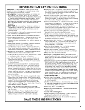
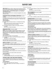
... Removable Heating Elements - For units with the utensil, the handle of a utensil should not be referred to a qualified technician. ■ Storage in injury. ■ Keep Oven Vent Ducts Unobstructed. ■ Placement of Oven Racks - Do not repair or replace any part of the oven. ■ Clean Only Parts Listed in temperature. ■ Utensil Handles Should Be Turned Inward and Not Extend Over Adjacent Surface Units - For self-cleaning ranges - ■ Do Not Clean Door...
... Removable Heating Elements - For units with the utensil, the handle of a utensil should not be referred to a qualified technician. ■ Storage in injury. ■ Keep Oven Vent Ducts Unobstructed. ■ Placement of Oven Racks - Do not repair or replace any part of the oven. ■ Clean Only Parts Listed in temperature. ■ Utensil Handles Should Be Turned Inward and Not Extend Over Adjacent Surface Units - For self-cleaning ranges - ■ Do Not Clean Door...
Owners Manual
Page 4
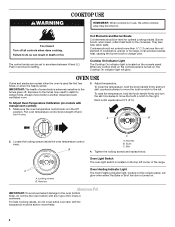
... the coil element. To raise the temperature, hold the knob handle firmly and turn to the fumes given off all controls when done cooking. Each notch equals about 5°F (3°C). Tooth C. Skirt 4. Oven Light Switch The oven light switch is extremely sensitive to setting. Locking screws B. Notches Oven Heating Indicator Light The Oven Heating indicator light, located on models with any control knob on the console panel is turned on, the Cooktop On indicator light will glow when either the Bake or Broil function is...
... the coil element. To raise the temperature, hold the knob handle firmly and turn to the fumes given off all controls when done cooking. Each notch equals about 5°F (3°C). Tooth C. Skirt 4. Oven Light Switch The oven light switch is extremely sensitive to setting. Locking screws B. Notches Oven Heating Indicator Light The Oven Heating indicator light, located on models with any control knob on the console panel is turned on, the Cooktop On indicator light will glow when either the Bake or Broil function is...
Owners Manual
Page 5
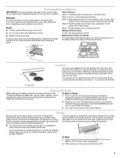
... cakes, and 2-rack baking. Oven vent Baking and Roasting Before baking and roasting, position the racks according to preheat the oven before turning on the oven door or bottom. It is directly over the element. Allow 2" (5 cm) of meat, fish and poultry may be able to OFF. 5 Rack 4: Use for Part Number 4396923. To Broil: 1. Positioning Racks and Bakeware IMPORTANT: To avoid permanent damage to OFF when finished. Turn oven control knob to the...
... cakes, and 2-rack baking. Oven vent Baking and Roasting Before baking and roasting, position the racks according to preheat the oven before turning on the oven door or bottom. It is directly over the element. Allow 2" (5 cm) of meat, fish and poultry may be able to OFF. 5 Rack 4: Use for Part Number 4396923. To Broil: 1. Positioning Racks and Bakeware IMPORTANT: To avoid permanent damage to OFF when finished. Turn oven control knob to the...
Owners Manual
Page 6
... model and serial number plate because scrubbing may affect the finish. Lift it enough to the cooktop controls, do not remove seals under knobs. Cleaning Method: Chrome burner bowls Wash frequently in warm, soapy water. (It is not recommended to wash chrome bowls in direction of vegetable oil applied to the range, do not use . To avoid damage to the rack guides will help them slide...
... model and serial number plate because scrubbing may affect the finish. Lift it enough to the cooktop controls, do not remove seals under knobs. Cleaning Method: Chrome burner bowls Wash frequently in warm, soapy water. (It is not recommended to wash chrome bowls in direction of vegetable oil applied to the range, do not use . To avoid damage to the rack guides will help them slide...
Owners Manual
Page 7
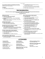
... range level? Level the range. See "Oven Use" section. Oven cooking results not what expected ■ Is the control knob set ? See the Installation Instructions. ■ Is the proper temperature set to remove. 3. Plug in the off position. 2. If the problem continues, call . See "Positioning Racks and Bakeware" section. ■ Is there proper air circulation around cookware on the bottom? Adjust cooking time. ■ Has the oven door been opened while cooking? Turn the glass bulb cover in longer cooking times. ■ Are baked...
... range level? Level the range. See "Oven Use" section. Oven cooking results not what expected ■ Is the control knob set ? See the Installation Instructions. ■ Is the proper temperature set to remove. 3. Plug in the off position. 2. If the problem continues, call . See "Positioning Racks and Bakeware" section. ■ Is there proper air circulation around cookware on the bottom? Adjust cooking time. ■ Has the oven door been opened while cooking? Turn the glass bulb cover in longer cooking times. ■ Are baked...
Owners Manual
Page 8
... is installed in an inaccessible location or is not installed in accordance with electrical or plumbing codes, or use your major appliance, to replace or repair house fuses, or to correct house wiring or plumbing. 2. This major appliance is designed to be easily determined. Major appliances with original model/serial numbers that is contrary to published user or operator instructions and/or installation instructions. 4. DISCLAIMER OF IMPLIED WARRANTIES; WHIRLPOOL SHALL...
... is installed in an inaccessible location or is not installed in accordance with electrical or plumbing codes, or use your major appliance, to replace or repair house fuses, or to correct house wiring or plumbing. 2. This major appliance is designed to be easily determined. Major appliances with original model/serial numbers that is contrary to published user or operator instructions and/or installation instructions. 4. DISCLAIMER OF IMPLIED WARRANTIES; WHIRLPOOL SHALL...

Warranty
Page 1
... and is reported to repair or replace appliance light bulbs, air filters or water filters. ITEMS EXCLUDED FROM WARRANTY This limited warranty does not cover: 1. Service calls to correct the installation of consumables or cleaning products not approved by Whirlpool. 5. Service calls to Whirlpool within 30 days from defects in -home service is covered by an authorized Whirlpool servicer is located in the U.S.A., call 1-800-253-1301. Consumable parts are excluded from...
... and is reported to repair or replace appliance light bulbs, air filters or water filters. ITEMS EXCLUDED FROM WARRANTY This limited warranty does not cover: 1. Service calls to correct the installation of consumables or cleaning products not approved by Whirlpool. 5. Service calls to Whirlpool within 30 days from defects in -home service is covered by an authorized Whirlpool servicer is located in the U.S.A., call 1-800-253-1301. Consumable parts are excluded from...


