Use and Care Manual
Page 2
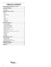
... Power 9 Manual Cooking 10 Cooking in Stages (or steps 10 Doneness 10 Quick Touch Cooking (sensor and non-sensor 10 Preset Cooking 12 Reheating 12 2-4 Plates 13 Defrosting 13 Warm Hold 13 MICROWAVE OVEN CARE 14 General Cleaning 14 Replacing Filters 15 Replacing Cooktop Light 15 Replacing Microwave Oven Light 16...
... Power 9 Manual Cooking 10 Cooking in Stages (or steps 10 Doneness 10 Quick Touch Cooking (sensor and non-sensor 10 Preset Cooking 12 Reheating 12 2-4 Plates 13 Defrosting 13 Warm Hold 13 MICROWAVE OVEN CARE 14 General Cleaning 14 Replacing Filters 15 Replacing Cooktop Light 15 Replacing Microwave Oven Light 16...
Use and Care Manual
Page 5
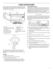
...Door safety lock system G. Cooktop light K. Rack will appear in either direction to use metal cookware, utensils, or a browning dish with 2 plates that are side by side. Do not let food container on automatically when cooking is over or CANCEL OFF is helpful when cooking with... top or sides of the microwave oven. See "Assistance or Service" section to touch the inside the turntable bottom ridge. Model and serial number plate C. Metal shielded window H. Microwave inlet cover L. Support The turntable can be turned off " icon will become hot. Always use a microwave-safe...
...Door safety lock system G. Cooktop light K. Rack will appear in either direction to use metal cookware, utensils, or a browning dish with 2 plates that are side by side. Do not let food container on automatically when cooking is over or CANCEL OFF is helpful when cooking with... top or sides of the microwave oven. See "Assistance or Service" section to touch the inside the turntable bottom ridge. Model and serial number plate C. Metal shielded window H. Microwave inlet cover L. Support The turntable can be turned off " icon will become hot. Always use a microwave-safe...
Use and Care Manual
Page 11
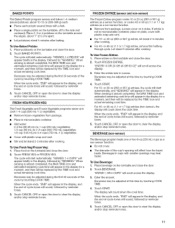
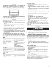
... touching COOK TIME. When the cycle ends, "END" will appear in the display, and the end-of the cycle by reminder tones. 3. Loosen cover on plate, cover with plastic wrap and vent. • Stir and let stand 2-3 minutes after cooking. • For 40- Let stand 5 minutes after cooking. Enter the entree...
... touching COOK TIME. When the cycle ends, "END" will appear in the display, and the end-of the cycle by reminder tones. 3. Loosen cover on plate, cover with plastic wrap and vent. • Stir and let stand 2-3 minutes after cooking. • For 40- Let stand 5 minutes after cooking. Enter the entree...
Use and Care Manual
Page 12
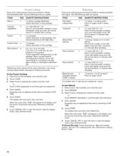
.... 1-6 pieces, 2 oz (57 g) each / Place on the turntable, and close the door. 2. Stir and let stand 2-3 minutes after reheating. 1 serving (1 plate), 8-10 oz (227283 g)/ Place food on paper towel. *For smaller rolls, 2 rolls may be counted as 1 piece. FOOD PAD QUANTITY/I NSTR UCTIONS Bacon* 1...sensor) Baked Goods 6 (example: medium muffin or bagel) 1-3 slices, 3 oz (85 g) each */ Place on plate, cover with plastic wrap and vent. Place food on paper towel or paper plate. 1-4 cups (250 mL-1 L)/ Place in the display, and the end-of fat, meat, thickness, and curing ...
.... 1-6 pieces, 2 oz (57 g) each / Place on the turntable, and close the door. 2. Stir and let stand 2-3 minutes after reheating. 1 serving (1 plate), 8-10 oz (227283 g)/ Place food on paper towel. *For smaller rolls, 2 rolls may be counted as 1 piece. FOOD PAD QUANTITY/I NSTR UCTIONS Bacon* 1...sensor) Baked Goods 6 (example: medium muffin or bagel) 1-3 slices, 3 oz (85 g) each */ Place on plate, cover with plastic wrap and vent. Place food on paper towel or paper plate. 1-4 cups (250 mL-1 L)/ Place in the display, and the end-of fat, meat, thickness, and curing ...
Use and Care Manual
Page 13
... follow a cooking cycle. To Use (for optimal results. Touch WARM HOLD. 3. Touch START. The Auto Defrost feature can be turned off while heating 2 bottom plates or 1 larger dish. Doneness may be heated side by side, or 1 dish larger than 1/4 Ib (113 g) or two 4 oz (113 g) patties. See... frozen ready-made food. The Auto Defrost system has 3 categories: Meat, Poultry and Fish. Do not defrost less than the turntable, plus 2 plates on the turntable, and close the door. 2. Turkey: breast FISH Fillets, Steaks, Whole, Shellfish Place in microwavable baking dish. Enter the weight ...
... follow a cooking cycle. To Use (for optimal results. Touch WARM HOLD. 3. Touch START. The Auto Defrost feature can be turned off while heating 2 bottom plates or 1 larger dish. Doneness may be heated side by side, or 1 dish larger than 1/4 Ib (113 g) or two 4 oz (113 g) patties. See... frozen ready-made food. The Auto Defrost system has 3 categories: Meat, Poultry and Fish. Do not defrost less than the turntable, plus 2 plates on the turntable, and close the door. 2. Turkey: breast FISH Fillets, Steaks, Whole, Shellfish Place in microwavable baking dish. Enter the weight ...
Installation Instructions
Page 1
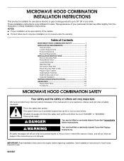
... COMBINATION SAFETY 1 INSTALLATION REQUIREMENTS 2 Tools and Parts 2 Location Requirements 2 Product Dimensions 3 Electrical Requirements 3 INSTALLATION INSTRUCTIONS 4 Remove Mounting Plate 4 Rotate Blower Motor 4 Locate Wall Stud(s 6 Mark Rear Wall 7 Drill Holes in these installation instructions. All safety messages will ...messages in this manual and on your particular model may differ slightly from the illustration in Rear Wall 7 Attach Mounting Plate to Wall 8 Prepare Upper Cabinet 8 Install Damper Assembly 9 Install the Microwave Oven 9 Complete Installation 10 VENTING ...
... COMBINATION SAFETY 1 INSTALLATION REQUIREMENTS 2 Tools and Parts 2 Location Requirements 2 Product Dimensions 3 Electrical Requirements 3 INSTALLATION INSTRUCTIONS 4 Remove Mounting Plate 4 Rotate Blower Motor 4 Locate Wall Stud(s 6 Mark Rear Wall 7 Drill Holes in these installation instructions. All safety messages will ...messages in this manual and on your particular model may differ slightly from the illustration in Rear Wall 7 Attach Mounting Plate to Wall 8 Prepare Upper Cabinet 8 Install Damper Assembly 9 Install the Microwave Oven 9 Complete Installation 10 VENTING ...
Installation Instructions
Page 2
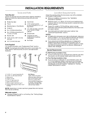
...; Minimum installation dimensions. For other damages. A B C D E FG H Location Requirements Check the opening . ■ Support for wall or roof venting) Not Shown: Upper cabinet template Mounting plate (attached to make sure there is at least 6" (15.2 cm) of any tools listed here. ■ Measuring tape ■ Stud finder ■ Pencil ■ 7/16...
...; Minimum installation dimensions. For other damages. A B C D E FG H Location Requirements Check the opening . ■ Support for wall or roof venting) Not Shown: Upper cabinet template Mounting plate (attached to make sure there is at least 6" (15.2 cm) of any tools listed here. ■ Measuring tape ■ Stud finder ■ Pencil ■ 7/16...
Installation Instructions
Page 4
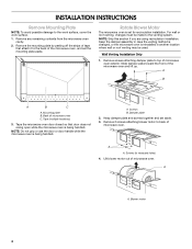
...: Do not grip or use the door or door handle while the microwave oven is being handled. Mounting plate B. Keep damper plate and screws together and set the mounting plate aside. Screws (in another location where wall or roof venting may be made to back of microwave oven ...system. Wall Venting Installation Only 1. Lift blower motor out of microwave oven C. Slide damper plate toward the front of the microwave oven, and set aside. 3. Damper plate 2. A Screws B. Remove the mounting plate by peeling off the strips of tape that door does not swing open while the microwave...
...: Do not grip or use the door or door handle while the microwave oven is being handled. Mounting plate B. Keep damper plate and screws together and set the mounting plate aside. Screws (in another location where wall or roof venting may be made to back of microwave oven ...system. Wall Venting Installation Only 1. Lift blower motor out of microwave oven C. Slide damper plate toward the front of the microwave oven, and set aside. 3. Damper plate 2. A Screws B. Remove the mounting plate by peeling off the strips of tape that door does not swing open while the microwave...

Installation Instructions
Page 5
... exhaust ports face the back of the microwave oven (as shown), performance will be reattached to the microwave oven. 7. Damper plate tabs 8. Damper plate tabs 8. A A A. Reattach blower motor to back of microwave oven with flat sides facing the back of microwave oven, ...and lower it back into microwave oven. Reattach damper plate. A D B C A. Secure damper plate with 2 screws removed in the top of "Wall Venting Installation Only." Repeat Step 2 from "Wall Venting Installation Only." 4. ...
... exhaust ports face the back of the microwave oven (as shown), performance will be reattached to the microwave oven. 7. Damper plate tabs 8. Damper plate tabs 8. A A A. Reattach blower motor to back of microwave oven with flat sides facing the back of microwave oven, ...and lower it back into microwave oven. Reattach damper plate. A D B C A. Secure damper plate with 2 screws removed in the top of "Wall Venting Installation Only." Repeat Step 2 from "Wall Venting Installation Only." 4. ...
Installation Instructions
Page 6
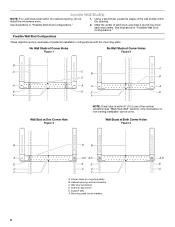
.... Wall stud centerlines D. No Wall Studs at Corner Holes Figure 1 No Wall Studs at Corner Holes Figure 2 MOUNTING PLATE MOUNTING PLATE MOUNTING PLATE MOUNTING PLATE B C C C B D D A A A A E E E E F F Wall Stud at Both Corner Holes Figure 4 MOUNTING PLATE MOUNTING PLATE MOUNTING PLATE MOUNTING PLATE B D B A A,D A,D A,D E E E E C C C C F F A. Wall Studs at One Corner Hole Figure 3 NOTE: If wall stud is within 6" (15.2 cm) of each stud...
.... Wall stud centerlines D. No Wall Studs at Corner Holes Figure 1 No Wall Studs at Corner Holes Figure 2 MOUNTING PLATE MOUNTING PLATE MOUNTING PLATE MOUNTING PLATE B C C C B D D A A A A E E E E F F Wall Stud at Both Corner Holes Figure 4 MOUNTING PLATE MOUNTING PLATE MOUNTING PLATE MOUNTING PLATE B D B A A,D A,D A,D E E E E C C C C F F A. Wall Studs at One Corner Hole Figure 3 NOTE: If wall stud is within 6" (15.2 cm) of each stud...
Installation Instructions
Page 7
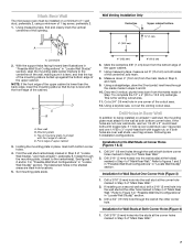
...one corner of "Mark Rear Wall." Refer to Figure 3 in "Possible Wall Stud Configurations" in place, mark both bottom corner holes. Centerline 2. Mounting plate C. D. See figures 1, 2 and/or 3 in "Possible Wall Stud Configurations" in Step 3 of upper cabinet 3. Mark the centerline 3/8" (1 cm)... Drill 3/4" (19 mm) holes through the marks made in Step 3 of the upper cabinet. 7. Drill a 3/4" (19 mm) hole through the mounting plate, closest to complete the 12" x 4" (30.5 x 10.2 cm) rectangle. With the support tabs facing forward (see illustrations in "Possible Wall Stud ...
...one corner of "Mark Rear Wall." Refer to Figure 3 in "Possible Wall Stud Configurations" in place, mark both bottom corner holes. Centerline 2. Mounting plate C. D. See figures 1, 2 and/or 3 in "Possible Wall Stud Configurations" in Step 3 of upper cabinet 3. Mark the centerline 3/8" (1 cm)... Drill 3/4" (19 mm) holes through the marks made in Step 3 of the upper cabinet. 7. Drill a 3/4" (19 mm) hole through the mounting plate, closest to complete the 12" x 4" (30.5 x 10.2 cm) rectangle. With the support tabs facing forward (see illustrations in "Possible Wall Stud ...

Installation Instructions
Page 8
... Studs at Corner Holes" in the "Drill Holes in Rear Wall" section. 6. B A C A. 1/4-20 x 3" round-head bolt B. Mounting plate C. Check alignment of mounting plate, making sure that it , trim the template edges so that the top of the microwave oven. The "rear wall" arrows must be against... sure the template centerline aligns with the front edge of "Installation for No Wall Studs at Corner Holes (Figures 1 & 2) NOTE: The mounting plate must be secured to outlet. 2. Spring toggle nut 3. With the support tabs of "Installation for One Wall Stud at both bottom corners. 1....
... Studs at Corner Holes" in the "Drill Holes in Rear Wall" section. 6. B A C A. 1/4-20 x 3" round-head bolt B. Mounting plate C. Check alignment of mounting plate, making sure that it , trim the template edges so that the top of the microwave oven. The "rear wall" arrows must be against... sure the template centerline aligns with the front edge of "Installation for No Wall Studs at Corner Holes (Figures 1 & 2) NOTE: The mounting plate must be secured to outlet. 2. Spring toggle nut 3. With the support tabs of "Installation for One Wall Stud at both bottom corners. 1....

Installation Instructions
Page 9
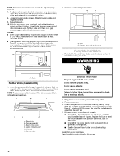
... Cut 3/4" (19 mm) hole at one corner of the upper cabinet. 5. Install Damper Assembly (for the power supply cord. A. Damper blade D. Mounting plate B. Cut the 1¹⁄₂" (3.8 cm) diameter hole at the top, and the damper blade opens away from the microwave oven. This hole is...power supply cord through the wall, make sure the damper assembly fits easily into the vent tube in place. 9 Push microwave oven against mounting plate and hold in the wall cutout. 6. For Roof Venting Installation Only 7. Check that the damper blade hinge is for wall venting only) 1....
... Cut 3/4" (19 mm) hole at one corner of the upper cabinet. 5. Install Damper Assembly (for the power supply cord. A. Damper blade D. Mounting plate B. Cut the 1¹⁄₂" (3.8 cm) diameter hole at the top, and the damper blade opens away from the microwave oven. This hole is...power supply cord through the wall, make sure the damper assembly fits easily into the vent tube in place. 9 Push microwave oven against mounting plate and hold in the wall cutout. 6. For Roof Venting Installation Only 7. Check that the damper blade hinge is for wall venting only) 1....
Installation Instructions
Page 10
... oven downward. Plug microwave oven into your model. Check the operation of microwave oven by operating the vent fan. 5. Adjust mounting plate and retighten screws. 9. Replace the fuse or reset the circuit breaker. If adjustment is not positioned as the space between upper cabinet... and microwave oven. Loosen mounting plate screws. A B A. Installation is now complete. NOTE: If microwave oven does not need to follow these instructions can result in place, ...
... oven downward. Plug microwave oven into your model. Check the operation of microwave oven by operating the vent fan. 5. Adjust mounting plate and retighten screws. 9. Replace the fuse or reset the circuit breaker. If adjustment is not positioned as the space between upper cabinet... and microwave oven. Loosen mounting plate screws. A B A. Installation is now complete. NOTE: If microwave oven does not need to follow these instructions can result in place, ...
Installation Instructions
Page 12
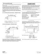
... you need the microwave oven model number and serial number. Each panel is located behind the microwave oven door on the model and serial number plate, which is 3" (7.6 cm) wide. A B 6 ft (1.8 m) 2 ft (0.6 m) C D A. Filler panels Filler Panel Kit Number 8171336 ... for either type of the installation hardware needs to use no more than three 90° elbows. Damper Assembly Part Number 8206442 Mounting Plate Part Number W10110277 Upper Cabinet Template Part Number 8205871 Mounting Screw Kit (includes parts A-G in China Recommended Vent Length A 3¹⁄₄...
... you need the microwave oven model number and serial number. Each panel is located behind the microwave oven door on the model and serial number plate, which is 3" (7.6 cm) wide. A B 6 ft (1.8 m) 2 ft (0.6 m) C D A. Filler panels Filler Panel Kit Number 8171336 ... for either type of the installation hardware needs to use no more than three 90° elbows. Damper Assembly Part Number 8206442 Mounting Plate Part Number W10110277 Upper Cabinet Template Part Number 8205871 Mounting Screw Kit (includes parts A-G in China Recommended Vent Length A 3¹⁄₄...

Parts Guide
Page 4
...) (Stainless) Illus. Part No. DESCRIPTION 1 8206387 Reflector, Lamp 2 8206232 Lamp 3 8206374 Holder, Lamp 4 8206229 Filter, Grease 5 8206386 Plate, Bottom 6 8206376 Glass, Lamp 7 8206375 Holder, Glass 8 8206345 Switch, Micro V5P010CG3 9 8206347 Switch, Micro V5P020CG3 10 8169438 Spring, Interlock 11 8183824...8206353 Bottom 13 8206558 Piston Assembly 14 8206180 Screw 15 8206357 Capacitor, 125 V 16 8206421 Thermistor (PCBA) 17 8206348 Plate, Side 18 8206358 Chassis Assembly 19 8206352 Switch, Micro V5P030CG3 20 8184312 Holder, Fuse 21 4393308 Fuse 22 8206359 Terminal...
...) (Stainless) Illus. Part No. DESCRIPTION 1 8206387 Reflector, Lamp 2 8206232 Lamp 3 8206374 Holder, Lamp 4 8206229 Filter, Grease 5 8206386 Plate, Bottom 6 8206376 Glass, Lamp 7 8206375 Holder, Glass 8 8206345 Switch, Micro V5P010CG3 9 8206347 Switch, Micro V5P020CG3 10 8169438 Spring, Interlock 11 8183824...8206353 Bottom 13 8206558 Piston Assembly 14 8206180 Screw 15 8206357 Capacitor, 125 V 16 8206421 Thermistor (PCBA) 17 8206348 Plate, Side 18 8206358 Chassis Assembly 19 8206352 Switch, Micro V5P030CG3 20 8184312 Holder, Fuse 21 4393308 Fuse 22 8206359 Terminal...
Parts Guide
Page 5
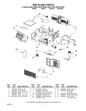
...7 W10107800 Shield 8 8206627 Air Guide 9 8206230 Filter, Charcoal 10 W10110862 Mounting, Nut (2) 11 8206625 Channel, Air 12 8206628 Air Guide,Plate 13 8206624 Filter Illus. Part No. AIR FLOW PARTS For Models: MH2175XSQ0, MH2175SXB0, MH2175XST0, MH2175XSS0 (White) (Black) (Biscuit) (Stainless...) Illus. No. No. Part No. DESCRIPTION 14 8169539 Holder, Lamp 15 8206383 Base Plate, Air Guide 16 8206368 Brkt−Mntg,Filter 17 8185097 Socket, Motor Wire 18 8206629 Cover, Inlet Air Cavity Guide 8206634 5 No. DESCRIPTION ...
...7 W10107800 Shield 8 8206627 Air Guide 9 8206230 Filter, Charcoal 10 W10110862 Mounting, Nut (2) 11 8206625 Channel, Air 12 8206628 Air Guide,Plate 13 8206624 Filter Illus. Part No. AIR FLOW PARTS For Models: MH2175XSQ0, MH2175SXB0, MH2175XST0, MH2175XSS0 (White) (Black) (Biscuit) (Stainless...) Illus. No. No. Part No. DESCRIPTION 14 8169539 Holder, Lamp 15 8206383 Base Plate, Air Guide 16 8206368 Brkt−Mntg,Filter 17 8185097 Socket, Motor Wire 18 8206629 Cover, Inlet Air Cavity Guide 8206634 5 No. DESCRIPTION ...