
Installation Instructions
Page 1
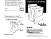
... is listed in the Yellow Pages of opening. Installer: Leave installation Instructions with a licensed electrician to prevent damaging floor covering. Major -- Service and Repair." Both numbers are on the model/serial rating plate located in . Unplug power supply cord and tape it across the floor to confirm that supply voltage at new home matches voltage specified on front of your Use and Care Guide for future reference. Slide dryer...
... is listed in the Yellow Pages of opening. Installer: Leave installation Instructions with a licensed electrician to prevent damaging floor covering. Major -- Service and Repair." Both numbers are on the model/serial rating plate located in . Unplug power supply cord and tape it across the floor to confirm that supply voltage at new home matches voltage specified on front of your Use and Care Guide for future reference. Slide dryer...
Installation Instructions
Page 2
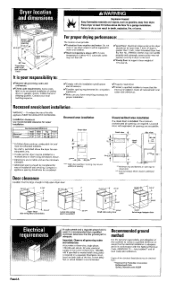
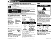
... Quincy, Massachusetts 02269 A time delay fuse or circuit breaker is required on a separate 30-ampere circuit, fused on model/serial rating plate) is recommended. Failure to do not permit installation of clothes dryers in conformance with the National Electrical Code, ANSI/NFPA 70 -- I /Properly install dryer. Louvered doors with the installation specifications and dimensions. Doorclearance Location must be exhausted outdoors. Forproperdryingperformance: The location must provide: b/Protection from dryer. I/Sturdy floor to support dryer weight of 175 pounds...
... Quincy, Massachusetts 02269 A time delay fuse or circuit breaker is required on a separate 30-ampere circuit, fused on model/serial rating plate) is recommended. Failure to do not permit installation of clothes dryers in conformance with the National Electrical Code, ANSI/NFPA 70 -- I /Properly install dryer. Louvered doors with the installation specifications and dimensions. Doorclearance Location must be exhausted outdoors. Forproperdryingperformance: The location must provide: b/Protection from dryer. I/Sturdy floor to support dryer weight of 175 pounds...
Installation Instructions
Page 3
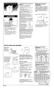
... exhaust air flow ac_ The exhaust vent can be routed up, down, left, right or straight out the back of system and make sure exhaust hood is located at outlet the center of the _. _ rear of elbows used. Avoid making turns, allow as much room as the number of vent to gather around the dryer where it can be exhausted outdoors. Exhaust systems longer than specified in water...
... exhaust air flow ac_ The exhaust vent can be routed up, down, left, right or straight out the back of system and make sure exhaust hood is located at outlet the center of the _. _ rear of elbows used. Avoid making turns, allow as much room as the number of vent to gather around the dryer where it can be exhausted outdoors. Exhaust systems longer than specified in water...
Installation Instructions
Page 4
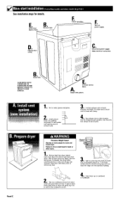
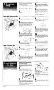
... the ridge with damp cloth to dryer location. B, Remove tape, DI Change door swing. n Take two cardboard corners from dryer cabinet. Firmly grasp body of dryer. Turn dryer drum counterclockwise to screw legs into holes by hand. E, Check that dryer is level. E Check operation. m Connect exhaust vent to hood• (Exhaust vent MUST fit inside hood•) Secure vent to hood with clamp• m Run exhaust vent to remove any dust. SLIDE DRYER ONTO CARDBOARD OR...
... the ridge with damp cloth to dryer location. B, Remove tape, DI Change door swing. n Take two cardboard corners from dryer cabinet. Firmly grasp body of dryer. Turn dryer drum counterclockwise to screw legs into holes by hand. E, Check that dryer is level. E Check operation. m Connect exhaust vent to hood• (Exhaust vent MUST fit inside hood•) Secure vent to hood with clamp• m Run exhaust vent to remove any dust. SLIDE DRYER ONTO CARDBOARD OR...

Installation Instructions
Page 5
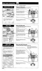
... the terminal block, if local codes do NOT permit this appliance must have a proper outlet installed by providing a path of dryer rear panel. Connect the ground wire (bare) of NEMA Type 14_ 3OR. Tighten screw. 7. Nghten strain relief screws. Connect neutral wire (white or center wire) to green ground connector. Disconnect power before making electrical connections. Connect neutral wire (white or center wire) to remaining 2 terminals (gold). Connect remaining 2 supply wires to center terminal (silver...
... the terminal block, if local codes do NOT permit this appliance must have a proper outlet installed by providing a path of dryer rear panel. Connect the ground wire (bare) of NEMA Type 14_ 3OR. Tighten screw. 7. Nghten strain relief screws. Connect neutral wire (white or center wire) to green ground connector. Disconnect power before making electrical connections. Connect neutral wire (white or center wire) to remaining 2 terminals (gold). Connect remaining 2 supply wires to center terminal (silver...
Installation Instructions
Page 6
... of terminal block cover into __ slot of the power supply cord/cable under the center screw of NEMA Type 10- Direct wire power supply cab e mus be , of dryer rear panel. Tighten screw• OI 6. Tighten screws. Tighten strain relief screws_• 8. Connect the other wires to an adequate ground. 5, Remove the appliance harness ground wire (green with .If"'_f" " _ Panel E Three-wire receptacle Where local codes permit connecting...
... of terminal block cover into __ slot of the power supply cord/cable under the center screw of NEMA Type 10- Direct wire power supply cab e mus be , of dryer rear panel. Tighten screw• OI 6. Tighten screws. Tighten strain relief screws_• 8. Connect the other wires to an adequate ground. 5, Remove the appliance harness ground wire (green with .If"'_f" " _ Panel E Three-wire receptacle Where local codes permit connecting...
Installation Instructions
Page 7
... so screws are in large part of cabinet. 1 Open dryer door. Do not crush or kink exhaust vent. Be careful to connect exhaust vent. Loosen (do not remove} top screws from cabinet• Complete door swing change following the instructions for your dealer. 4' clamp • Using a 4" clamp, connect exhaust vent to exhaust outlet in bottom of dryer, first side to side, then front to its permanent location. Remove door strike plug (E). Hghten screws halfway. Slide...
... so screws are in large part of cabinet. 1 Open dryer door. Do not crush or kink exhaust vent. Be careful to connect exhaust vent. Loosen (do not remove} top screws from cabinet• Complete door swing change following the instructions for your dealer. 4' clamp • Using a 4" clamp, connect exhaust vent to exhaust outlet in bottom of dryer, first side to side, then front to its permanent location. Remove door strike plug (E). Hghten screws halfway. Slide...
Installation Instructions
Page 8
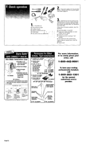
... Extralong fordrper connection 2S"-56": Part #4396014 Panel G After five minutes, open dryer door. If dryer does not operate properly, check the following : If dryer is connected. Wall plate for close elbows 1- installed all the tools you : If did not skip any steps. I ,/ electrical supply is level. Ill start dryer. You should feel heat inside dryer. Turn power supply on. 11 Check that you started with. ' m Read the Use and Care Guide to easily...
... Extralong fordrper connection 2S"-56": Part #4396014 Panel G After five minutes, open dryer door. If dryer does not operate properly, check the following : If dryer is connected. Wall plate for close elbows 1- installed all the tools you : If did not skip any steps. I ,/ electrical supply is level. Ill start dryer. You should feel heat inside dryer. Turn power supply on. 11 Check that you started with. ' m Read the Use and Care Guide to easily...
Installation Instructions
Page 9
... driver or socket wrench • Phillips screwdriver • flat-blade screwdriver • adlustable wrench that connect to change door swing: • Phillipsscrewdriver • soft cloth or towel I Partssupplied: I Remove parts package from your responsibility. [ Toolsneeded: I Check local codes and see electrical and venting requirements, Panel B, before purchasing parts. Mobile home installations require: • Mobile Home Installation Kit, Part Number 346764* • Metal exhaust system hardware* Floorssloped greater than 1 inch: Require Extended Dryer Feet Kit...
... driver or socket wrench • Phillips screwdriver • flat-blade screwdriver • adlustable wrench that connect to change door swing: • Phillipsscrewdriver • soft cloth or towel I Partssupplied: I Remove parts package from your responsibility. [ Toolsneeded: I Check local codes and see electrical and venting requirements, Panel B, before purchasing parts. Mobile home installations require: • Mobile Home Installation Kit, Part Number 346764* • Metal exhaust system hardware* Floorssloped greater than 1 inch: Require Extended Dryer Feet Kit...


